International Journal of Scientific & Engineering Research, Volume 5, Issue 5, May-2014
ISSN 2229-5518 1226
WDM Optical Communication Networks
Performance Comparison using different Fibers
Poonam Singal
Abstract— While optical transmission techniques have been researched for quite some time, optical networking studies have been taken up in last few years only. The field has evolved and many different fibers have come up to overcome hindrances in smooth flow of data at higher rates. The objective of this paper is to discuss at length the current optical networking trends along with the role of different kind of fibers in development of different networks.
E are moving in an era which requires that we have access to information at our fingertips as and when required and whatever format we need it. Fiber optic technology is the best means of meeting our above mentioned demands because of its limitless advantages. Huge bandwidth, low attenuation, low signal distortion, low power requirement, low space requirement, light in weight and endless. The challenge is to turn the advantages of fiber
optics to meet the demands of information networking.
WDM is a technique which can exploit the huge optoelectronic bandwidth by multiplexing multiple WDM channels from different end users on the same fiber. The advantage of WDM over other multiplexing techniques is that here, the end users electronic equipment operate only at electronic rate. In optical TDM, the bit rate is aggregate of all TDM channels in the system. Therefore some part of end users network interface must operate at a rate higher than electronic speed. By allowing multiple WDM channels to co exist on a single fiber, one can tap into huge fiber bandwidth. Research and development on optical WDM networks have matured considerably and a number of experiment prototypes have been and are currently being developed, deployed and tested mainly by telecommunication
companies.
Optical fiber networks using WDM techniques can be classified either as Broadcast and Select networks or Wavelength Routed Networks. a broadcast and select network strategy based on Star Coupler is shown in Fig.1.

Fig 1
Optical Transmission is broadcast to all nodes using fixed transmitters and tunable receivers which extract the desired signal from all multiplexed transmitted signals. As the number of nodes increases, each station receives lesser fraction of total transmitted power. In the concept of
IJSER © 2014 http://www.ijser.org
International Journal of Scientific & Engineering Research, Volume 5, Issue 5, May-2014
ISSN 2229-5518 1227
wavelength Routed Networks, using the wavelength specified, any network node can transmit or receive a signal from another node in the network. This strategy of wavelength implementation or path selection is shown in Fig
2.
Fig 2.
Both Broadcast and select and Wavelength routed networks can be classified into Single Hop and MultiHop. Single Hop allows direct communication between any two nodes and data remains entirely in optical domain. In a MultiHop, transmission may take place through intermediate nodes before reaching its destination. At each intermediate node the data can be switched electronically to next possible node and it is then retransmitted as an optical signal. This conversion is inefficient but necessary.
Given a situation as shown in fig 3 where node
1 needs to get connected to node 3. The solid lines show the channels in use. In this case Node 1 will be first connected to node 2 via wavelength λ1 and then at node 2 ,a conversion from λ1 to λ2 is desirable because that is the only available wavelength channel. Such networks are called wavelength convertible networks. In some networks only few nodes have this facility known as sparse wavelength convertible architecture.
In dense WDN networks, a light path is established by reserving a particular wavelength on the physical links between source and destination nodes. It is a two stage search and select process related to both routing and wavelength assignment. The implementation of RWA can be static or dynamic.
One form of a wavelength add drop multiplexer is shown in fig 4.It consists of a De-mux followed by a set of 2x2 switches—one switch per wavelength followed by a MUX. The WADM can be essentially inserted on a physical fiber link. If all 2x2 switches are in Bar state then all wavelengths flow through WADM undisturbed. However, if one of the 2x2 switches is configured in Cross state then the signal on the corresponding wavelength is dropped locally and a new data stream can be added on to same wavelength at this WADM location. An OADM can form part of traffic on a wavelength or it may drop a band of wavelengths.
Fig 4.
Fig 3
These are the fiber interconnection devices. Passive star is a broadcast device so a signal that is inserted on a given wavelength from an input fiber port will have its power equally divided among all o/p ports.
IJSER © 2014 http://www.ijser.org
International Journal of Scientific & Engineering Research, Volume 5, Issue 5, May-2014
ISSN 2229-5518 1228

Fig 5
Passive Router can separately route each of several wavelengths incident on an input fiber to the same wavelength on separate o/p fiber, e.g. wavelengths λ1 λ2 λ3 and λ4 incident on I/p fiber 1 are routed to same corresponding wavelengths to o/p fibers 1 2 3 4 respectively. This device allows wavelength reuse which means that the same wavelength may be spatially reused to carry multiple connections through the router. This is depicted in fig. 5.
Fig 6.
Active Switch: Also allows wavelength reuse and can support N2 simultaneous connections through it. Its routing matrix can be reconfigured.
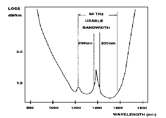
The low attenuation regions of conventional fibers are depicted in fig 6.A conventional fiber suffers
1385nm water peak window and hence its bandwidth is reduced.
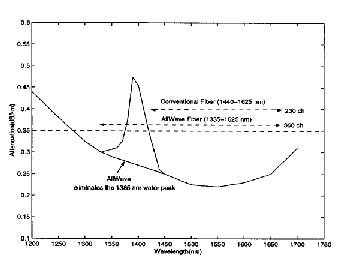
Fig 7 ( ZWP : Zero Water Peak)
Recent developments in fiber optics have further expanded the usable fiber bandwidth. A new type of fiber called ALL WAVE FIBER does not have the 1385 nm water peak window and it provides a more usable optical spectrum. Fig 7 shows the low attenuation regions of All Wave Fiber in comparison to a conventional fiber.

The ultra wideband EDFA can fully exploit the expanded low attenuation region of AA WAVE FIBER. Before All Wave ZWP Fiber was introduced, systems were limited to operating in either the ‘O’ band(1310nm) window or C and L bands(1530nm
IJSER © 2014 http://www.ijser.org
International Journal of Scientific & Engineering Research, Volume 5, Issue 5, May-2014
ISSN 2229-5518 1229
to 1625nm).With the availability of All Wave fiber, the E band(1400nm) is available to inexpensively expand the capacity of Optical Networks. All Wave ZWP fiber offers the lowest loss of all commercial LWP fibers in the industry. It sets the benchmark and maintains leadership with specifications that are fully compliant with ITU-T-G.652 standards for SMF.
Low Optical loss across entire wavelength range from 1260nm to 1625nm, tightest available geometry, low splice loss and low PMD. These features combined with complete compatibility with embedded fiber base, provide ultimate network design flexibility and enable cost effective solutions. It supports most demanding applications, including 10
Giga Bit Ethernet, Asynchronous transfer mode(ATM),10 and
40 Gbit/s(SONET) and SDH(Synchronous Digital Hierarchy)using single channel, DWDM and CWDM transmission .
1. Fully compatible withal conventional single mode fibers
2. Low optical loss
3.Absence of Hydrogen Ageing defects and using high purity synthetic silica ensures long term attenuation reliability across(1260-1625nm)
4.A 50% increase in usable optical spectrum enabling 16 channel CWDM and DWDM support.
5. Best in class, ultra low fiber PMD
6. Outstanding reliability
7. Protected by OFS U.S. patents
8. Provides N/W designer maximum flexibility to meet today’s demanding requirements
Ref [c]
It is a new class of optical fiber based on the properties of photonic crystals. Because of its ability to confine light in hollow cores or with confinement characteristics not possible in conventional optical fibers, PCF is now finding applications in fiber optic communication.
1. Low non linear losses, supporting high power pulses
2. Made of undoped silica as core and air as cladding, complete control over core and cladding index properties
3. Low bending loss
4. PCF has great potential for WDM transmission use because of its endlessly single mode properties Ref[A]
5. By optimizing the thermal conditions of fiber drawing and optimizing the core glass composition, we can reduce losses in PCF. Since PCF is composed of a single material, these approaches are more effective. We can select the glass composition freely and need not consider the imperfection loss caused by mismatch between viscosity of core and cladding as in conventional fibers. Intrinsic low loss glasses are available for fabricating PCF. PCF will allow us to expand wavelength regions and increase distance for WDM transmission. Ref [B]
It is concluded that performance of optical network could be improved by replacing conventional fibers with Photonic Crystal fibers and All wave fibers
A: K. Tajima, J. Zhou, K. Nak , Ultra Low Loss and Long length PCF – OFC 2003, PDI ( 2003)
B: K. Tajima, J. Zhou, K. Tsujikana . reduction is official loss of conv & PCF., OSA 2003
C: Data from OFS,Leading Wave Innovations
IJSER © 2014 http://www.ijser.org