International Journal of Scientific & Engineering Research, Volume 4, Issue 6, June‐2013
(ISSN 2229-5518)
1957
VARIABLE FREQUENCY DRIVES IN POWER DISTRIBUTION Author: Vishv Mohan (State Topper Himachal Pradesh 2008, 2009, 2010) B.E(Hons.) Electrical and Electronics Engineering ; ID-No.: 2010A3PS016P
University: Birla Institute Of Technology & Science, Pilani -333031(Rajasthan)-India
![]()
Abstract: Using VFDs for frequency regulation, in
consonance with transformers, for household electricity-supply; the reactive-power (i.e, VAr demand) can be reduced and the power factor gets increased to enhance the efficiency of power transmission. Thus the VFDs have a vital role to save energy in power systems. As the transformer performs the function of stepping-up or stepping down the voltage at constant frequency, if the Variable Frequency Drives will be used in consonance with transformer for optimum frequency regulation then a tremendous amount of energy can be conserved which can be used for other constructive purposes. This paper has experimentally showed the results where the power transmission and power distribution at lesser frequency is energetically more favorable, in energy conservation point of view. At any point of time, VFDs make the power transmission at relatively low frequency to minimize the power transmission & distribution losses as per the load demand so that the energy can be saved and transmission losses can be reduced to a great extent. The graphical representation of the paper tells at which point the reduction in frequency is favorable for efficient power transmission and distribution.
Introduction:
A Variable Frequency Drive (VFD) is a type of motor controller that drives an electric motor or any electric equipment by varying the frequency and voltage, as per load requirement, supplied to the electric motor. Other names for a VFD are variable speed drive, adjustable speed drive, adjustable frequency drive etc.
If we have an application that does not need to be run at full speed, then we can cut down energy costs by controlling the motor with a variable
frequency drive, which is one of the benefits of
Variable Frequency Drives. VFDs allow us to match the speed of the motor-driven equipment to the load requirement. Usage of VFDs is for better regulation and control of the system, Reduce system cycling, Reduce maintenance cost, Energy savings (almost all cases).
The next thing that can happen in future is the installation of VFDs in consonance with Transformers for household power supply; where the transformer will perform the function of stepping up or down the input voltages and the VFDs will regulate the frequency accordingly in collaboration with load requirement, thereby energy can be saved. An optimal point is required to be set, below which the fall in frequency is favorable in order to conserve the energy, i.e.; for efficient energy usage.
All the equipment’s need not to be run at constant load all the time, hence power can be supplied at relatively lesser frequency so that it must fulfill the output load demand and at the same time, it should cut down the reactive power demand hence, enhancing the power saving capacity. With the reduction in VA demand, the power factor gets improved and efficiency of motor can be increased many folds
In VFDs AC is converted (or more precisely gets![]()
magnified of about √ time) into DC voltages ;
then using capacitor, the output voltage waveform
is smoothened and harmonics are removed out, then DC voltage in again converted into AC voltage using pulse width modulation (PWM) into smaller pulses using IGBTs. The load requirement is tested by sensors which are used in feedback mode and; accordingly the frequency is modified
at supply terminal.
1
IJSER@2013
International Journal of Scientific & Engineering Research, Volume 4, Issue 6, June‐2013
(ISSN 2229-5518)
1958
Block Diagram: As the supply is given at required frequency, the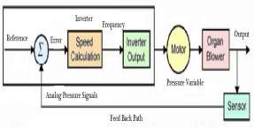
speed can be adjusted accordingly and wear & tear of motor or electrical equipment can be reduced, leads to the increase in life-span of electric-motors. With the reduction in supply-power-frequency, the power-factor increased significantly which results in efficient energy usage by amplifying its
efficiency.
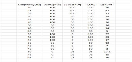
Varying Frequency Table
Graphical Inference
2
IJSER@2013
International Journal of Scientific & Engineering Research, Volume 4, Issue 6, June‐2013
(ISSN 2229-5518)
1959

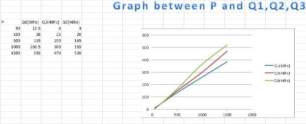
The upper most line represents the supply of
power at 50 Hz which explicitly shows the greater
VA demands i.e. more power loss during power transmission or distribution. While middle line shows the supply of power at 48 Hz; which gives the power loss relatively lesser than the supply at
50 Hz. The lower line shows the power supply at
46 Hz; which is the most efficient in comparison to power supply at 50 Hz or 48 Hz. According to the graph the supply at 46 Hz is more favorable, from energy conservation point of view, for a particular load requirement. For smaller loads requirements
in parallel at household application, as the
frequency goes down, the reactive power
correspondingly reduces; for efficient energy usage. If the power will be distributed at 46Hz for given load requirement (depicted by green line in graph), the VA demand will be less and energy can be saved, rather than supplying the power at fixed frequency of 50Hz (depicted by blue line in graph).
Graphical Inferences
3
IJSER@2013
International Journal of Scientific & Engineering Research, Volume 4, Issue 6, June‐2013
(ISSN 2229-5518)
1960
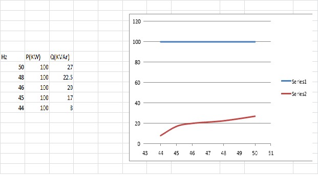
The above graph shows that for a fixed load of
100KW, as the power supply is given in a reducing frequency trend, the corresponding reactive power reduces. Graph tells the load requirement of
100KW can be maintained at 44 Hz giving lesser reactive power; as is the target. If the power is supplied at constant frequency of 50 Hz, then there will be more VA losses.
If the VFDs will be used for frequency control,
after the voltage get stepped-up or stepped-down by the transformer, the reactive power will decrease as, there is decrease in switching losses etc; thereby energy can be saved.
The above graph represents that the power
transmission is favorable at higher frequency only for higher load requirements. But all the time, all the appliances/ equipment / motors need not to be
run at full speed; at that point of time, we need to
give power supply at relatively lesser frequency, in order to minimize the VA demand i.e. to reduce down the reactive power demand. For the load of
4
IJSER@2013
International Journal of Scientific & Engineering Research, Volume 4, Issue 6, June‐2013
(ISSN 2229-5518)
1961
100KW, as the supply is given to the load at 50 Hz,
48 Hz and 46 Hz respectively; the reactive power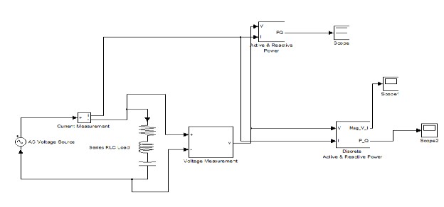
(KVAr) at the output end reduces significantly.
Graph represents that for smaller load
requirements; supply can be given as lesser frequency to minimize the energy losses.
Discussion:
The most significant benefit to using a VFD is energy savings. By matching system capacity to the actual load throughout the entire year, major savings in system motor energy use are achieved.
Another benefit of the units is reduced wear and tear on the motors. When an induction motor is started, it draws a much higher current than during normal operation. This inrush current can be three to ten times the full-load operating current for the motor, generating both heat and stress in the motor's windings and other components. In motors that start and stop frequently, this contributes to early motor failures.
In contrast, when a motor connected to a VFD is started, the VFD applies a very low frequency and low voltage to the motor. Both are gradually ramped up at a controlled rate to normal operating
conditions, extending motor life by reducing the
wear and tear of the motor. VFDs also provide more precise levels of control of applications. For example, high-rise buildings use a booster pump system on the domestic water supply to maintain adequate water pressure at all levels within the building. Conventional pump controls in this type of application can maintain the pressure within certain range, but a VFD-based system can maintain more precise control over a wider range of flow rates, while reducing energy requirements and pump wear.
One of the most successful energy management tools ever applied to building HVAC systems is the variable frequency drive (VFD). For more than 20 years, VFDs have successfully been installed on fan and pump motors in a range of variable load applications. Energy savings vary from 35 to 50 percent over conventional constant speed
5
IJSER@2013
International Journal of Scientific & Engineering Research, Volume 4, Issue 6, June‐2013
(ISSN 2229-5518)
1962
applications, resulting in a return on investment of
six months to two years.
While the number of applications suitable for early generation drives was limited based on the horsepower of the motor, today's drives can be installed in practically any HVAC application found in commercial and institutional buildings. Systems can be operated at higher voltages than those used by earlier generations, resulting in off the shelf systems for motors up to 500 horsepower.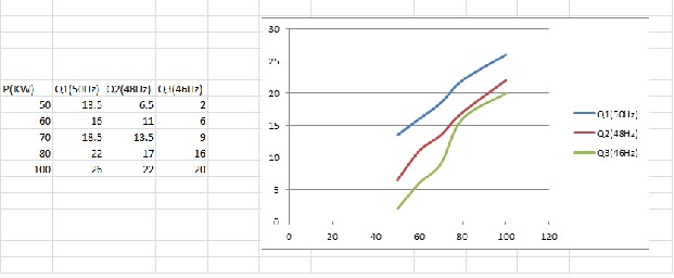
Early generation systems also suffered from low power factor. Low power factor robs the facility of electrical distribution capacity and can result in cost penalties imposed by electrical utility companies. Today's systems operate at a nearly constant power factor over the entire speed range
of the motor. Energy saving a critical issue before
almost every country; which can be managed to a great extent, by using VFDs.
Another problem that has been corrected by today's systems is operational noise. As the output frequency of the drives decreased in response to the load, vibrations induced in the motor laminations generated noise that was easily transmitted through the motor mounts to the building interior. Today's drives operate at higher frequencies, resulting in the associated noise being above the audible range.
For the load requirement varying from 50KW to
100KW; the above graph says that the power supply at relatively lesser frequency is favorable in order to save the energy. For instance, the load requirement of 80KW, the reactive power is 22
KVA, 17 KVA, 16KVA at the frequency 50Hz, 48Hz and 46Hz respectively. This represents that the
power supply at lesser frequency is energetically
favorable as it is giving less reactive power and at
the same time maintain the respective load requirement at the receiving end. The uppermost line in the graph is the line representing the power transmission at 50 Hz. The middle one line is the line representing the power transmission at 48Hz. The lower most line is the line showing the power
transmission at 46 Hz, which is more energy
6
IJSER@2013
International Journal of Scientific & Engineering Research, Volume 4, Issue 6, June‐2013
(ISSN 2229-5518)
1963
conserving as it has lesser reactive power
components.
(5.)VFDs help in power-factor correction and torque-speed relation
In variable torque applications, the torque required varies with the square of the speed, and the horsepower required varies with the cube of the speed, resulting in a large reduction of horsepower for even a small reduction in speed. The motor will consume only 25% as much energy at 50% speed than it will at 100% speed. Variable speed drives, and the loads they are applied to, can generally be divided into two groups: constant torque and variable torque. The energy savings potential of variable torque applications is much greater than that of constant torque applications. Variable torque loads include centrifugal pumps and fans, which make up the majority of HVAC applications. Constant torque loads include vibrating conveyors, punch presses, rock crushers, machine tools, and other applications where the drive follows a constant V/Hz ratio.
Single-speed starting methods start motors abruptly, subjecting the motor to a high starting torque and to current surges that are up to 10 times the full-load current. Variable speed drives, on the other hand, gradually ramp the motor up to operating speed to lessen mechanical and electrical stress, reducing maintenance and repair costs, and extending the life of the motor and the driven equipment.
Soft starts, or reduced-voltage soft starters (RVSS), are also able to step a motor up gradually, but drives can be programmed to ramp up the motor much more gradually and smoothly, and can operate the motor at less than full speed to decrease wear and tear. Variable speed drives can also run a motor in specialized patterns to further minimize mechanical and electrical stress. For example, an S-curve pattern can be applied to a
conveyor application for smoother decel/accel
control, which reduces the backlash that can occur when a conveyor is accelerating or decelerating.
Due to adjustable speed-torque phenomenon, the following are the advantages:
1.) Adjusting/reducing speed as per the requirements .
2.) Improve power-factor.
3.) Reduce copper-loss (as current req. can be modified.)
4.) Reduction in VA demands.
5.) Smooth start-up (otherwise 6-time current req. for start-up.)
6.) Improve voltage regulation.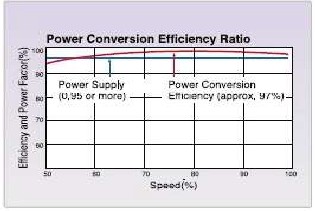
Using VFDs, the reduction in speed leads to the increment in power factor and thereby efficiency gets enhanced upto 96 to 98 percent.
VFDs also provide more precise levels of control of applications. For example, high rise buildings use a booster pump system on the domestic water supply to maintain adequate water pressure at all levels within the building. Conventional pump controls in this type of application can maintain the pressure within a certain range, but a VFD based
7
IJSER@2013
International Journal of Scientific & Engineering Research, Volume 4, Issue 6, June‐2013
(ISSN 2229-5518)
1964
system can maintain more precise control over a
wider range of flow rates, while reducing energy requirements and pump wear.
Reference:
1. IGF Fertilizers Plant at Jagdishpur Lucknow (UP) Confidential Electrical Manual efficiency and speed relationship graph has been taken from internet.
2. Transformer Concept from
Basic Electrical Engineering,
3. ‘Electric Machines’, D.P. Kothari and
I.J. Nagrath.
By: Vishv Mohan, s/o Sh. Vasu Dev Sharma
H.No.: 1 ; Roura-Sec:03, Bilaspur(H.P)
State Topper Himachal Pradesh 2008,2009,2010
B.E(Hons.) Electrical And Electronics Engineering
BITS-Pilani (Rajasthan) India vasuvishv@gmail.com
8
IJSER@2013