International Journal of Scientific & Engineering Research Volume 3, Issue 12, December-2012 1
ISSN 2229-5518
Dr. Salah F. A. Sharif a* , Dr. Ahmed Kasikci b**
a- College of Engineering, UNITEN, Malaysia, b- ALBA Electro Technology LTD., Izmir-Turkey
*A Prof, Research Fellow, E-mail: salah@uniten.edu.my, H/P: (+60147315069),
** Power Transmission Consultant Eng., E-mail: altektic@hotmail.com, H/p: (+ 905327940851)
*** Iraq DESERTEC: Is the Proposed Electricity Generation Project to Supply Europe through Turkey
In this paper, the impacts of a very high voltage overhead DC transmission power lines, were estimated and investigated. An Ultra High Voltage Direct Current Lines (UHVDCL) was proposed to transmit about 6000 Megawatts power for 2800 Km distance from Iraq to Romania, as a gate to European Countries, through Turkey under DESERTEC Concepts. Recent technological developments and practices have shown that, +/- 800 Kilovolt Bipolar UHVDC line can undertake this task quite well. Since the voltage is very high in comparison to the average transmission voltages it is necessary to investigate the values of Electrostatic and Electromagnetic field densities under or in the vicinity of subject transmission line. Such very high voltage conductors are kept high enough from the ground so that their adverse effects to environment should be as low as possible. Similar lines have been installed in China for 2070 kilometers distance and transmitted 6400 Megawatts recently. In this case study, +/-
800 KV line conductors have been kept 18 meters (Minimum) from the ground. This applied distance has been adopted in the proposed line. Calculations made by using the generally employed formulas have shown in this study that the effect of Electrostatic and Electromagnetic field intensities are below the limits recommended by ICNIRP (International Commission of Non-Ionizing Radiation Protection).
UHVDC Transmission Lines, Electromagnetic Fields, Electrostatic Fields, Desertec Projects.
Very large amount of electric power can be transmitted for long distances by the High Voltage Direct Current (HVDC) transmission line. If the voltage is equal or above 800 kilovolt then it is called Ultra High Voltage Direct Current (UHVDC) lines.
In the year 2010, about 2070 km long UHVDC line was constructed in China and subject line transmitted 6400 Megawatts from Xiangjiaba to Shanghai (Chan-Ki Kim, et.al. 2009).
On the other hand, European Community is planning to collect clean electric energy from
Middle East and North African Countries, in order to meet their future power demand. The
IJSER © 2012
International Journal of Scientific & Engineering Research Volume 3, Issue 12, December-2012 2
ISSN 2229-5518
European Community has created a project called “DESERTEC” for this purpose. Since there is abundant amount of solar energy supported with huge reserve of natural gas in Iraq, it is suggested to harvest this abundant power from Iraq by converting the solar and gas powers to electricity and transmit the electric power to Europe through Turkey. This concept does not contradict “DESERTEC Projects”.
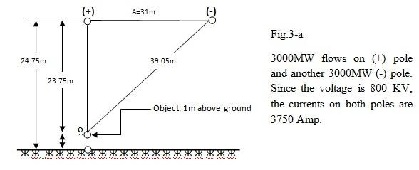
To transmit the generated electric power from Iraq to Europe, it is assumed to install an UHVDC overhead transmission line in length of 2800 kilometers to Romania which is a gate to European Community. Power transmission experts have made the preliminary design of subject UHVDC transmission line which can transmit 6000 Megawatt from Iraq to Romania (The First Stage of the Project). The UHVDC line should be “Bipolar” type and the voltage on positive pole should be +800 Kilovolts and the voltage on negative pole should be -800
Kilovolts. The (+) pole will transmit 3000 Megawatts and (-) pole will also transmit 3000
Megawatts, totaling 6000 Megawatts (Salah F. A. Sharif, 2012).
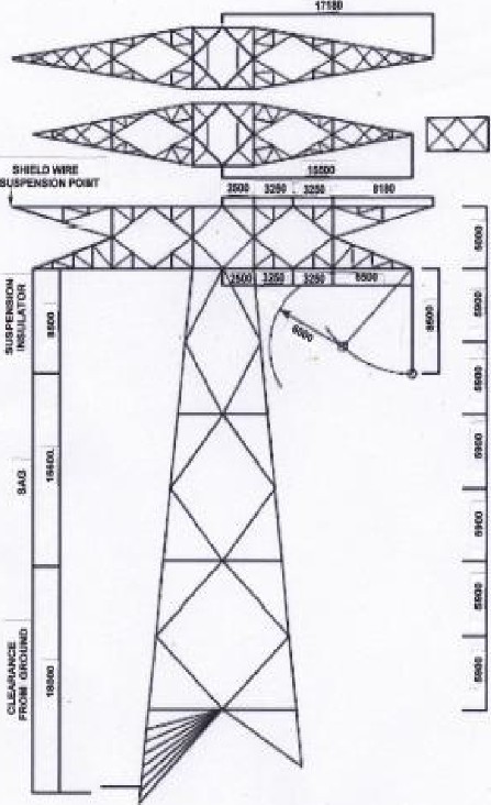
Based on this assumptions and using the main dimensions experienced in several countries for
+/-800 Kilovolts bipolar lines, the basic dimensions of a Suspension Tower is illustrated in
Fig.1.
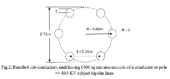
In order to reduce power losses to minimum, the cross sectional area of one pole is calculated to be 6000 sq.mm All Aluminum Alloy Conductor (AAAC). This 6000 sq.mm area shall be obtained by using 6 numbers of 1000 sq.mm AAAC conductors on a circumference of a circle having 0.72 m in diameter. Both (+) and (-) poles will have the same configurations. The minimum clearance from lowest point of conductors to ground is kept minimum 18 meter in order to reduce electrostatic and electromagnetic fields intensities. Because the lower the intensities, is the lesser the Environmental Impacts. The diameter of the circle on which the AAAC sub conductors are distributed will also affect the intensities. The Larger the Diameter, is the lesser the Environmental Impacts. In this preliminary design, the diameter of this circle was taken 0.72 meters (E. W. Kimbark, 2011).
Environmental issues are addressed in permitting process of every transmission line project. Environmental effects on humans, animals, and plant life and other electrical and communication systems also must be assessed in every case (IEEE Transactions on Geosciences Electronics, 1978).
Although different than AC lines, the UHVDC lines also produce environmental effects that warrant review and assessment in every project.
In the West of Iraq, Al-Anbar Province region, a huge amount of solar power in addition to natural gas is available. First considerations have identified a promising project by combining these available resources with possibilities for power export.
IJSER © 2012
International Journal of Scientific & Engineering Research Volume 3, Issue 12, December-2012 3
ISSN 2229-5518
The general thought is to use solar power during daytime plus natural gas during night time and to export the generated power via a transmission system to either Turkey or even Europe. The envisaged power amounts to 6,000 MW, for the first stage.
For this purpose, the natural gas from existing wells will be exploited and brought by pipelines near the Euphrates River where 6 x 1,000 MW gas fired power plants will be constructed. In addition a feasible amount of solar power plants shall be erected which will supply a part of 6,000 MW during daytime. The output of all these power plants will separately be brought by 400 KV AC overhead lines to the north of Euphrates river, where 2 x
3,000 MW converter stations shall be established in the north of Euphrates river to convert
400 KV AC to +/ - 800 KV DC. The obtained DC power with +/- 800 KV potential shall be transmitted by overhead lines to Turkey or Romania as an entrance to Europe.
Environmental study is needed to assess possible harm to the nature, humans, flora and fauna. The CO2 and other harmful flue gas emissions should be minimized using latest technologies (Lahmeyer international GMBH, 2011). This paper is concerned with the expected environmental impacts due to the proposed UHVDC line.
The electrical environment of high voltage transmission line can be characterized by three electrical parameters:
a) Electrical Fields (Electrostatic Fields)
The electric (or electrostatic) field arises from both the electric charges (voltage) on conductors of UHVDC line, charges on air ions and particles, surrounding the conductor. Corona phenomenon is produced by electric field and this may produce low levels of ozone. It produces also audible noise and interfere radio and TV broadcastings.
b) Magnetic Field (Electromagnetic Field)
Magnetic field is produced by current flowing through the conductors. The electric and magnetic field of UHVDC line are constant under normal operating conditions.
c) The Air Ions and Charged Particles Concentrations
The air ions produced by “corona” of AC lines, are neutralized by the time varying fields, so they are not an issue. But ions produced by UHVDC line form clouds and drift away from the line and may come in contact with humans, animals and plants outside the transmission line right-of-way. Indeed ions have been the focus of extensive research as noted in many articles written about environmental impact of
UHVDC transmission lines (Dennis A. Woodford Manitoba, 1998).
IJSER © 2012
International Journal of Scientific & Engineering Research Volume 3, Issue 12, December-2012 4
ISSN 2229-5518
The measuring unit of Electric Field is: (KV/m).
The measuring unit of Magnetic Field is: (Tesla or Gauss).
ICNIRP Exposure Guidelines for Electric and Magnetic Fields under or In the Vicinity of Power Lines are: ** (ICNIRP Electromagnetic Field (EMF) guidelines, 1998).
a- For Electric Field: 10,000 V/m or 10 KV/m
b- For Magnetic Field: 500 Micro Tesla
** ICNIRP: International Commission on Non-Ionizing Radiation Protection.
An important point to make is that a guideline limit is not precise delineation between safety and hazard. There is no one level above which exposures become hazardous to health, instead, the potential risk to human health gradually increases with higher exposure levels. Guidelines indicate that, below a given threshold, electromagnetic field exposure is safe according to scientific knowledge. However, it does not automatically follow that, above the given limit, exposure is harmful. As humans cannot be used for experiments, guidelines critically rely on animal studies. Guidelines recommended the prevention of electromagnetic field exposure
levels, at which behavioral changes become noticeable (William H. Bailey, et. al. 1997).
IJSER © 2012
International Journal of Scientific & Engineering Research Volume 3, Issue 12, December-2012 5
ISSN 2229-5518
![]()
IJSER 2012
http: //www. ijser .qg
International Journal of Scientific & Engineering Research Volume 3, Issue 12, December-2012 6
ISSN 2229-5518
Possible effects associated with the interaction of EMF from transmission lines with people on or near the right-of-way fall into two categories: short term effects and long term effects. Only short term effects shall be discussed here below. The long term effects associated with transmission lines are controversial. In recent years, considerable research on possible biological effects of EMF has been conducted (William H. Bailey, et. al. 1997). The followings are short term effects.
Electric Fields, Short Term Effects
Short-Term effects from transmission-line electric fields are associated with perception of induced currents and voltages or perception of the field. Induced current or spark discharge shocks can be experienced under certain conditions, when a capacitively charged person contacts metal objects. A very small current in few microampere levels flows from hand of person to metal object in the shape of spark. This does not harm the person, but gives annoyance.
The magnitude of the electric charge, due to electric field under transmission line will depend on the magnitude of electric field strength, the size and shape of the object. When an object is electrically grounded, the induced charge on the object is reduced to zero, and it is not a source of current or voltage shocks. If the object is poorly grounded, then there will be a very weak spark when the object is contacted fully to ground.
The responses of persons to steady-state charge shocks have been extensively studied, and levels of responses are documented (Keesey and Letcher, 1970).
Primary shocks are those that can result in direct physiological harm. Such shock will not be possible from induced charges under the existing lines, because clearances above ground required by safety standards preclude such shocks from large vehicles and grounding practices eliminate large stationary objects as a source of such shocks.
Secondary shocks are defined as those that could cause an involuntary and potentially harmful movement, but no direct physiological harm. Secondary shocks could occur under high voltage transmission line when making contact with ungrounded metallic object such as a large bus with rubber tires. However such occurrences are anticipated to be very infrequent. Induced charges are always present under high voltage transmission lines. However during the construction period and before energizing the line, the metal objects under or near the right-of-way, must be routinely grounded by the contractors. The groundings eliminate these objects as sources of charges and voltage shocks. Multiple
grounding points are used to provide redundant paths for induced charge (current) flow.
IJSER © 2012
International Journal of Scientific & Engineering Research Volume 3, Issue 12, December-2012 7
ISSN 2229-5518
Unlike fences or buildings, mobile objects such as vehicles and farm machinery cannot be grounded permanently. Limiting the possibility of induced charges from such objects to persons is accomplished in several ways. First, required clearances for overhead conductors tend to limit field strengths to levels that do not represent hazard or nuisance. The NESC (National Electricity Safety Code) of 2002 requires that, for high voltage lines, a sufficient conductor clearance, are maintained to limit the spark current in the largest anticipated vehicle, under the line to 5 milli-amperes, or less. This can be accomplished by limiting access or by increasing the conductor clearances in areas where large vehicles could be present.
In electric fields under high voltage transmission lines, it is theoretically possible for a spark discharge from induced voltage on a large vehicle to ignite gasoline vapor during refueling. The probability for exactly right conditions to occur for ignition is extremely remote. Vehicles should not be refueled under high voltage lines unless specific precautions are taken to ground the vehicle and the fueling source.
Potential impacts of electric fields can be mitigated through grounding policies. Shielding by conducting objects, such as vehicles and vegetations, also reduces potential for electric field effects.
Magnetic Fields, Short Term Effects
Magnetic fields associated with transmission systems can induce voltage and current in long conducting objects that are parallel to the transmission line. As with electric-field induction, these induced voltages, and currents are a potential source of shocks. A fence, pipeline, irrigation pipe, electrical distribution or telephone line, forms a conducting loop when it is grounded at both ends. The earth forms the other portion of the loop. The magnetic field from a transmission line can induce a current to flow in such a loop if it is oriented parallel to the line. If only one end of the fence is grounded, then an induced voltage appears across the open end of the loop. The possibility of a shock exists if a person closes the loop at the open end by contacting both the ground and the open end of the fence. The magnitude of this potential shock depends on the following factors:
- The magnitude of the field.
- The length of the object such as fence. The longer the object, the larger the induced voltage.
- The orientation of the object with respect to the transmission line. If parallel, the effect is max. If perpendicular, the effect is zero.
- The amount of electrical resistance in the loop
Magnetically induced currents have been investigated for many years. Calculation methods and mitigation measures are available. A comprehensive study of gas pipelines near transmission lines developed prediction methods and mitigation techniques
IJSER © 2012
International Journal of Scientific & Engineering Research Volume 3, Issue 12, December-2012 8
ISSN 2229-5518
specifically for induced voltage on pipelines (Keesey and Letcher, 1970). Similar techniques and procedures are available for irrigation pipes and fences. Grounding policies employed by utilities for long fences reduce the potential magnitude of induced voltage.
Magnetic fields from transmission and distribution facilities can interfere with certain electronic equipment. Magnetic fields have been observed to cause distortion in the operation of said electronic equipment. This can occur in the fields as low as 10 milli Gauss, depending on the size and type of the device. Contemporary display devices using flat panel technologies, such as liquid crystal or plasma displays are not affected.
Interference from magnetic fields can be eliminated by shielding the effected device or moving it to an area with lower fields.
Regulation that apply to transmission line electric and magnetic fields fall into two categories:
- Safety standards or codes are intended to limit or eliminate electric shocks that could seriously injure or kill persons.
- Field limits or guidelines are intended to limit electric and magnetic field exposures that can cause nuisance shocks or might cause health effects.
In no case has a limit or standard been established because of a known or demonstrated health effect. The electrical clearances specified in the codes, provide safe distances that prevent harmful shocks to workers or the public in the vicinity or under the lines. In addition, the people who live and work near transmission lines must be aware of safety precautions to avoid electrical contact with the conductors.
Field limits or guidelines have been adopted in several countries by national and international organizations. Electric-field limits have generally been based on minimizing nuisance shocks or field perception. The intent of magnetic field limits has been to limit exposures to existing levels, given the uncertainty of their potential for health effects (EPRI, Electric Power Research Institute USA, 2011).
General guidelines for electric and magnetic field exposure have been established for occupational and public exposure by national and international organizations.
Previously it was mentioned that (+) pole and (-) pole conductors are consisted of 6nos of sub conductors each having 1000 sq.mm stranded All Aluminum Alloy.
IJSER © 2012
International Journal of Scientific & Engineering Research Volume 3, Issue 12, December-2012 9
ISSN 2229-5518
Corona is defined as an electrical discharge accompanied by a luminous phenomena as the result of ionization of the air surrounding a conductor. It occurs when the electric field strength exceeds a critical value.
A distinction is made between two zones around the conductor:
• Ionization zone
• Space charge zone
The ionization zone is a thin layer around the sub conductors. Its thickness is of the order of magnitude of one tenth of a percentage of the distance between the electrodes. In this zone, the high field strength causes charge carriers to collide at high velocity with air molecules and ionize them. The electrons released, are accelerated toward the positive conductor and away from the negative one, and thus once again, collide with air molecules, causing an avalanche effect to occur. Some of the charge carriers penetrate into the space between the conductor and ground, that is, into the space charge zone, where they are decelerated and ultimately recombine. Since these charge carriers are constantly from the ionization zone, an ion current and associated corona losses are produced. The critical field strength at which ionization begins has been determined by experiments to be 29.8 KV/cm. In tests with industrially manufactured sub conductors, the corona effect was however, found to occur at voltages as low as approximately 15 KV/cm. The reason for this effect at such low field strength is the presence of small defects and irregularities in the surface of the sub-conductors which lead to local areas on which the critical field strength exceeded. The maximum field strength which occurs on the sub-conductor surface can be calculated if the following parameters are known:
• Conductor-to-ground voltage: …………………… (Ud), in KV.
• Radius of the sub-conductor: ………………..… (r), in meter.
• No of sub-conductors per pole bundle: ………….. (N) Number.
• Distance between the sub-conductors in bundle: … (S), in meter.
• Height of conductor above ground at mid-span: …. (H), in meter.
• Distance between (+) pole and (-) pole
Formulae indicated in the literature, some of which are quite complicated, give results which are only approximately correct. One reason is that, with increasing voltage, the ionization zone expands, so that a conductor bundle ultimately appears as a cable of correspondingly
large diameter (Lahmeyer international GMBH, 2011).
IJSER © 2012
International Journal of Scientific & Engineering Research Volume 3, Issue 12, December-2012 10
ISSN 2229-5518
Sub-conductor surface gradient can be described in general by the following equation:![]()
E = (U_d jr)
(KV/m)…………………………………………….……..….. (Eq.1)
2H 2H N
2H 2
![]()
![]()
![]()
![]()
( ) 2
In subject line, the values are as follows: Ud = +800 KV or - 800 KV
r = 0.0411m /2 = 0.02055m for 1000sq.mm.AAAC.
H = 18 m (Distance from ground to lowest point of conductor) N = 6 sub-conductors![]()
![]()
![]()
= r N = 0.36 ((6 0.2055) j 0.36) = 0.30112 m.
A = 31 m. (Distance between (+) pole and (-) pole
X = -1 for bipolar line
If design values are used in the above given formula (eq.1), E is found as 1350.51 KV/m.
This corresponds to 13.50 KV/cm on the surface of sub-conductor. This value is quite good because it is well below the critical value of 22 KV/cm.
The maximum sub-conductor surface gradient of bundle is found to be:
IJSER © 2012
International Journal of Scientific & Engineering Research Volume 3, Issue 12, December-2012 11
ISSN 2229-5518
Ema = 13.50 1 + ( - 1)![]()
r KV/cm. …………………………………..…… (Eq.2)
R
Emax = 13.50 {1+ (6-1) * (0.02055/0.36)} = 17.35 KV/cm.
The Radio and TV interference emanating from subject +/- 800 KV UHVDC bipolar lines is:
Fo = 25 + 10 log 0 + 20 log 0 r + 1.5(Ema - 22) dB …………………………(Eq.3)
Fo = 25 + 10 log 0 6 + 20 log 0 2,055 + 1.5(17.35 - 22) = 32.06 dB
Fo = 32.06 dB < 45 dB, Which is below the limit and not harmful for Radio and TV
broadcasting. (In this calculation r has taken as 2.055cm because Emax taken in KV/cm).
The corona effect causes a wide band electromagnetic radiation which can lead to interference particularly with AM radio transmission. The source of these radiations is widely different. On the (-) conductor, there are “Trichel” pulses which are distributed which are distributed approximately in a uniform manner over the surface of the sub-conductors and contribute very little to the radio interference. On the (+) conductor, there are several mechanism which can be observed. The major contribution to the high frequency interference generated by bipolar line is formed “streamers” which are distributed more randomly.
In an investigation of environmental factors on UHVDC lines, Radio Interference (RI) is found to decrease during rainy periods contrary to AC lines. Also significant seasonal effect was reported, with RI interference being lower in winter. The reason for that is at low temperatures, the absolute moisture content of the air is significantly lower, although the relative humidity in winter is generally higher than in summer.
Interference in the TV range, of course, is theoretically conceivable, but measurements have shown that the noise level in this frequency is so low that there is no reason to fear any interference beyond the right-of-way of an UHVDC line.
Ionization caused by corona, represents a partial breakdown in air; this high-energy potential discharge causes a local compression and decompression of the air, which is propagated as an acoustical wave through the air. Since in subject line the Fo =32 dB, the acoustical noise is also relatively low.
While within the ionization zone, corona current is carried by electrons, while current between the conductors and between conductor and ground, is carried by ions and other charged particles. It is important to note that in AC lines this effect does not exist. The charge carriers
which are accelerated in one direction in one-half-wave are decelerated in opposite direction,
IJSER © 2012
International Journal of Scientific & Engineering Research Volume 3, Issue 12, December-2012 12
ISSN 2229-5518
only a few of them “escaping” into open space. On the other hand currents are induced by capacitive coupling in conductive objects which reach value of 16 microampere per 1 KV/m electric field strength. If a person stands on the ground under the AC line, at 5 KV/m, field intensity, the induced current is 80 microamperes. It is important to keep this value in mind when effects caused by ion current underneath the UHVDC line.
If the physiological effects of the current flowing through the human body, which range between “barely perceptible” and “ painful shock” are investigated, it can be concluded that physiological effect to be expected from UHVDC line are very much less than those of from an UHVAC lines.
An additional effect caused by ion current is the charging of objects which are under DC line and which are well insulated from the ground. Well insulated fences under DC line could be cause of concern. It has been determined that a fence running a 10 meters parallel to HVDC line for several kilometers, can cause an “unpleasant” shock. Such a very theoretical case can, easily, be eliminated by grounding the fence.
Previously, it was mentioned that, the guideline of International commission on Non-Ionizing Radiation protection (ICNIRP), shows that 500 micro Telsa, as a maximum value for electromagnetic field strength. The maximum electromagnetic field strength vertically under (+) pole or (-) pole of the subject UHVDC line must be below this 500 micro Telsa.
For overhead transmission line, there is a concept of “Everyday temperature” which means an average temperature in which the sag of conductors can be assumed to be constant all the year around. The experts calculated the “Everyday sag” of the conductor for subject UHVDC line and it was found 13.12 m. In this case the distance from ground to lowest point of conductor is 20.38 m. one third of 13.12 m sag should be added to this 20.38 m and it will be: 20.38+ (1/3)*13.12 = 24.75m. This is the distance from ground to “Everyday” position of the
conductors in the air (Rakosh Das Begamudre, 1990).
IJSER © 2012
International Journal of Scientific & Engineering Research Volume 3, Issue 12, December-2012 13
ISSN 2229-5518
'Po = 3.723*10-4 Tesla :: 373*10-6 Tesla = 373 micro Tesla
Similar value can be found under (-) pole as well. Then: 373 micro Tesla < 500 micro Tesla
This calculated value is the maximum of all other points and it is less than the limit value recommended by ICNIRP.
ICNIRP has given max value of electrostatic voltage gradient as 10000volts/m or 10KV/m. The electrostatic field gradient at point “o” can be calculated as follows:
It is necessary to form the Maxwell’s potential matrix at first. For this reason, we have to know equivalent radius of the conductor. This was calculated, previously, as 0.3011m.
'Po = 2 -7
IJSER © 2012
International Journal of Scientific & Engineering Research Volume 3, Issue 12, December-2012 14
ISSN 2229-5518
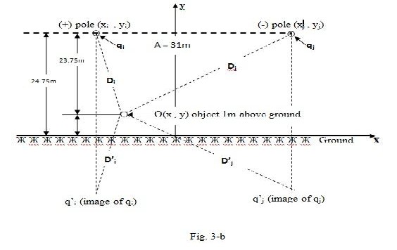
Vertical components of Electrostatic Field Gradients can be calculated by using the formulas shown below (Rakosh Das Begamudre, Extra High Voltage A.C. Transmission Engineering,
Willey Eastern limited, 1990).
Evi =![]()
qi
2rr€o
![]()
(y yi ) -
i
![]()
D2 (KV/m) …………………….…………………. (Eq.4)
Evj =![]()
qj
2rr€o
![]()
(y yj )
2 -
j
![]()
(y y )
2 (KV/m) ………………………………….……. (Eq.5)
j
Ev = Evi + Evj (KV/m) ………………..……………………… (Eq.6)
/2n€o = [p] V = M V (Voltage will be in KV) ……..…….……………... (Eq.7)
pii pij
P is Maxwell’s Potential Matrix =
ij jj
………………..……………………….. (Eq.8)![]()
p = p = :: n2
eq
![]()
p = :: n ij
ij
……………………..……………..……….. (Eq.9)
Where: H= 24.75m, req= 0.3011m, Aij= 31.0m, Iij = 58.40
Pii = Pjj = fn (49.5 / 0.3011) = 5.10 , Pij = fn (58.40 / 31.0) = 0.633
p = 5.100 0.633 ……………..….This is Maxwell’s potential matrix for subject line.
0.633 5.100
IJSER © 2012
International Journal of Scientific & Engineering Research Volume 3, Issue 12, December-2012 15
ISSN 2229-5518
p = M = 0.1990 -0.0247
-0.0247 0.1990
……This is the Inverse of Maxwell’s potential matrix.
The qi charge represents (+) pole and qj charge represents (-) pole in subject line. From (Eq.7):
qi/2n = M V = 0.166 * (+800) = +159.2 KV for the (+) pole.
qj/ = M V = 0.166 * (-800) = - 159.2 KV for the (-) pole.
In order to determine the maximum Electrostatic Voltage Gradient, a point, just under (+) pole
and 1.0m above the ground level, should be taken.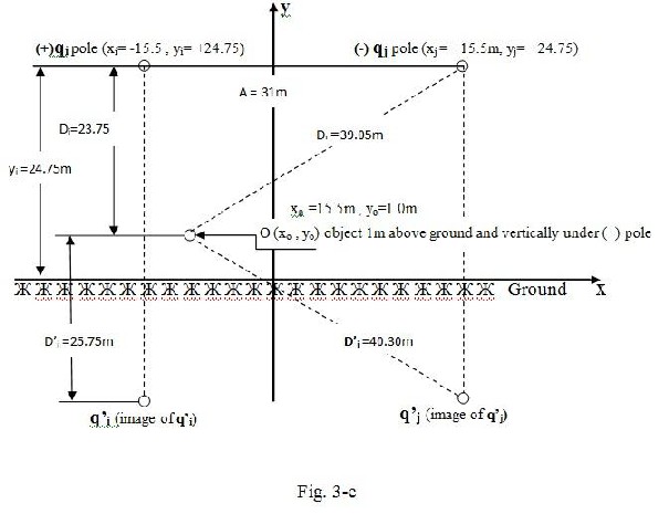
Evi = +159.20 * [(1-24.75) / (23.75)2 – (1+24.75) / (25.75)2 = -12.885 KV/m
Evj = - 159.20 * [(1-24.75) / (39.05)2 – (1+24.75) / (40.30)2 = + 5.004 KV/m
IJSER © 2012
International Journal of Scientific & Engineering Research Volume 3, Issue 12, December-2012 16
ISSN 2229-5518
Ev = Evi + Evj = - 12.885 + 5.004 = - 7.881 KV/m < 10 KV/m
The value 7.881 KV/m is the maximum Electrostatic Field Gradient, which is smaller than limit of 10.0 KV/m.
The similar Electrostatic Field Gradient, on an object, 1m above ground level and vertically under (-) pole will be: Ev = +7.881 KV/m.
At the origin of the coordinates, or just at the center of the tower, Ev = 0 KV/m.
Calculated value just (15.5/2) m on the left and right of the center is: E = -/+ 4.868 KV/m. Also, calculated value just 50m on the left and right of the center is E = -/+ 2.715 KV/m.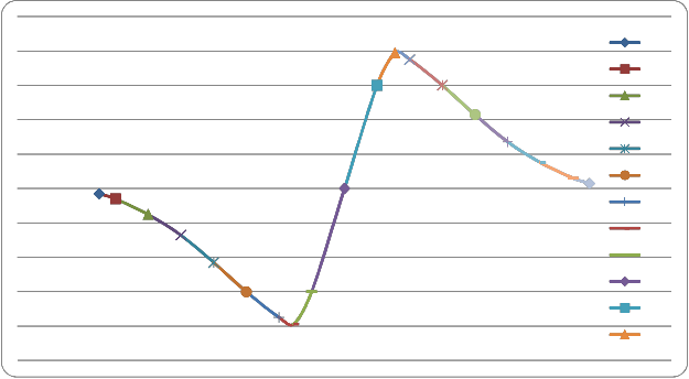
Fig.4 below shows a graph representing the Electrostatic Field Gradients in the vicinity of subject +/- 800 KV UHVDC overhead transmission line.
Fig.4 Electrostatic Field Gradient of subject +/- 800 KV UHVDC Transmission line -75
-70
-60
-50
-40
-30
-20
-15.5
-10
0
10
15.5
IJSER © 2012
International Journal of Scientific & Engineering Research Volume 3, Issue 12, December-2012 17
ISSN 2229-5518
1- Chan-Ki Kim, Vijay K. Sood, Gil-Soo Jang, Seong-Joo Lim and Seok-Jin Lee “HVDC Transmission Power Conversion Application in Power Systems”, (John Wiley & Sons
/Asia), 2009.
2- Dennis A. Woodford Manitoba, “HVDC Transmission”, HVDC Research Center, March 1998.
3- E. W. Kimbark, “Direct Current Transmission” (John Wiley & Sons), 1971.
4- EPRI (Electric Power Research Institute USA), “HVDC and FACTS Technologies”,
2011 Research Portfolio.
5- ICNIRP Electromagnetic Field (EMF) guidelines, Health Physics 74, 494-522, 1998.
6- IEEE Transactions on Geosciences Electronics, Vol. Ge-16, No. 1, January 1978. Man and Climate: An Overview. Earl W. Barrett.
7- Keesey and Letcher, 1970, “Microampere Electrocution during Hae1nodialysis”, an - ERA-EDTA, www.era-edta.org/.../vol11/vol11%20210_213.pd.
8- Lahmeyer international GMBH, Al Anbar Investment Commission, “Integrated Solar Thermal Power Plants in the Al Anbar Region of Iraq”, Terms of Reference for Consulting Services for Preparing a Pre-Feasibility Study, Oct. 2011.
9- Rakosh Das Begamudre, “Extra High Voltage A.C. Transmission Engineering” (Wiley
Eastern Limited), 1990.
10- Salah F. A. Sharif, “The Project; Iraq Desertec Is the Future Second Electricity Supplier to Europe through Turkey”, IJSER Volume 3, Issue 11, November 2012 (ISSN 2229-5518).
11- William H. Bailey, Deborah E. Weil and James R. Steward “HVDC Power
Transmission Environmental Issues Review Oak Ridge National Laboratory”, (US Department of Energy), 1997.
IJSER © 2012