International Journal of Scientific & Engineering Research, Volume 3, Issue 6, June-2012 1
ISSN 2229-5518
Thermo-Economic Analysis of a Desalination Device from the Second law of Thermodynamics’ Point of View and Parameter Investigation
![]()
Kashi.A, Aghanajafi C
Abstract—In this paper, exergy will be explained, and the MED desalination system will be introduced. Then, the simultaneous productio n cycle will be investigated, and it’s analysis from thermodynamic and exergy points of views will be presented. Finally It’s products will be considered. The main purpose of this study is to investigate the effects of some parameters such as entering pressure of the desalination system and the number of heat recovery systems on our desired parameters. Additionally, this system will be optimized economically in a way that both thermodynamic and economic cases are considered.
Index Terms— Economic and thermal optimization, Exergy, The Second law of Thermodynamics’, Desalination MED.
—————————— ——————————
HESE days, producing drinking water is of great importance specially in hot and dry areas where the availability of drinking water is really low. In the following picture, the hot and dry areas with low amount of drinking
water are specified [4].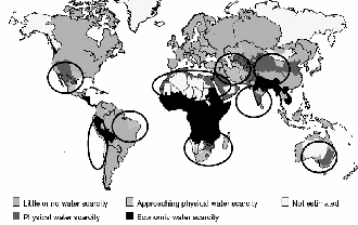
Fig. 1.Global water scarcity
Because of the high costs of producing water, using desalination systems has become very common. There are different types of desalination systems the MED of which is going to be investigated in this paper [5], [6].Coupling a production cycle with a desalination system is a very suitable approach from thermodynamic and economic points of views
————————————————
Kashi.A⃰, Aghanajafi.C
Department of Mechanical Engineering, K.N.T. University of
Technology, Tehran, Iran
⃰E-mail: Amin_kashi64@yahoo.com
in which external gases from the gas turbine can be used as a portion of the needed energy for the desalination system.
Also, a part of the exiting vapor could be used for the
desalination system [4].
First, the essence of exergy will be explained, and it’s relation with enthalpy and the first and the second laws of thermodynamics will be considered [7], [8], [9]. Then, the simultaneous production cycle will be investigated for exergy a thermodynamic points of views, then useful relationships will be written [10], [11]. Energy is available in different forms and changes to various kinds. Different energies have different qualities.The quality of the energy is defined by means of entropy [12], [13]. High entropy is equal to low quality and vice versa. The second law of thermodynamic indicates that only the changes are possible during which the total entropy increases. By introducing exergy, we can consider energy and entropy simultaneously.For more understanding the concept, consider the following procedure [1], [2], [3], [14]: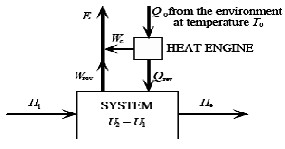
Fig. 2. A schema of thermodynamic system
IJSER © 2012 http://www.ijser.org
International Journal of Scientific & Engineering Research, Volume 3, Issue 6, June-2012 2
ISSN 2229-5518
![]()
![]() (1)
(1)
![]()
![]()
![]()
![]()
![]()
![]() (2)
(2)
Now, assume two environments with heat capacity of ![]() and
and ![]() and temperatures of
and temperatures of ![]() and
and ![]() and constant volumes. The equilibrium temperature is calculated like [14]:
and constant volumes. The equilibrium temperature is calculated like [14]: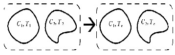
![]()
![]()
![]()
![]() (3)
(3)
From the second law of thermodynamics:
(4)![]()
![]()
In which ![]() is out of entropy and
is out of entropy and ![]() is the entropy
is the entropy![]()
related to ![]() .
.
Fig. 4. Schema of heat transfer in environments
(12)![]()
![]()
![]()
The second law of thermodynamics indicates:
(5)
(6)![]()
Total entropy production is:
(13)
So, the work of the heat engine can be expressed as follows: ![]()
![]() (7)
(7)
Replacing ![]() and
and ![]() in above equation will result in:
in above equation will result in:![]()
![]()
![]()
A simple introduction to exergy of materials is presented in the following. In standard states, temperature and pressure are assumed constant [14].![]()
![]()
![]()
![]()
![]()
![]()
![]()
(14)![]()
Which could be rewritten as :
(8)
Where ![]() is the generalized chemical potential of specy i and
is the generalized chemical potential of specy i and ![]() is the generalized chemical potential of specy i in its environment state.
is the generalized chemical potential of specy i in its environment state.![]()
![]()
For pure elements:![]()
![]()
![]()
![]()
Consider the following picture:![]()
![]()
![]()
(9)![]()
In which ![]() is the concentration of specy i. So:
is the concentration of specy i. So:
(15)![]()
![]()
(16)
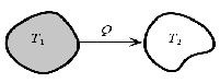
Fig. 3. schema of heat transfer between 2 particles
Specific amount of heat ![]() transfers from the object number 1 with the temperature of
transfers from the object number 1 with the temperature of ![]() to the object number 2 with the temperature of
to the object number 2 with the temperature of ![]() . Entropy changes of the objects are:
. Entropy changes of the objects are:
![]() (10) The total change of the entropy is:
(10) The total change of the entropy is:
![]()
(11)
It’s worth mentioning that ![]() is the concentration of substance i at standard atmosphere (101 Kpa and
is the concentration of substance i at standard atmosphere (101 Kpa and ![]() ).Now
).Now
that we have gotten familiar with the concept of exergy, we will investigate the MED desalination systems.
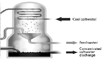
This device is built on the basis of evaporation and condensation of salted water (sea water) in multiple stages; which means periodic evaporations and condensations are done which increase the efficiency of the system. This kind of desalination system is made up of several heat recovery sections and one heat rejection system and one Thermo- Compressor. The necessary energy of the desalination system is maintained by the dry vapor from a boiler. This dry vapor is mixed with the vapor from the last heat recovery system and
IJSER © 2012 http://www.ijser.org
International Journal of Scientific & Engineering Research, Volume 3, Issue 6, June-2012 3
ISSN 2229-5518
compressed by the Thermo-Compressor and then is guided to the first heat recovery system. This internal vapor of the heat recovery system moves and causes the vapor to turn into
saturated water. The produced water from the first condensation is the first water product which is produced by the first heat rejection system. As it can be seen from fig (5), the pipes’ group including vapor are cooled by spraying sea water (Salted water) on them. Water spray on pipes’ group causes some of the water to evaporate. Considering the internal temperature and pressure of the heat recovery system, it can be said that the amount of evaporated water inside the heat recovery system equals the amount of water which is condensed in condensation pipes.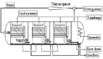
Fig. 5. Desalination-MED
The produced vapor in the first heat recovery system, after passing demisters, enters the pipes of the second heat recovery system as the entering vapor and in this heat recovery system, too, some sea water is used to cool group of pipes. Next, this water evaporates and then condenses and the drinking water of the second heat recovery system is produced during this process which is exits the heat recovery system. This procedure continues this way.
In the last heat recovery system, the exiting heat is guided
to the heat rejection system, and the heat from this vapor is transferred to the sea water which is going to be used as the feeding water of the system. In the heat rejection system, a great amount of water is exposed to heat transfer, so the sea water never evaporates [5], [21].
Salty sea water, after pre-purifying and getting ready to be used in desalination device, enters the heat rejection system. In the heat rejection system, the heat of the outlet vapor from the last heat recovery system is transferred to the feeding water and pre-heats it in a way that its temperature increases to ![]() . In general, the entering water to the heat rejection system is divided into two parts in a way that one part of which is the feeding water which is used for desalination
. In general, the entering water to the heat rejection system is divided into two parts in a way that one part of which is the feeding water which is used for desalination
process and enters heat recovery systems, and the other of which has the role of water coolant which is brought back to the sea. The entering water to heat recovery systems is
sprayed on pipes through which water vapor passes by means of spraying nozzles. This water climbs down the pipes as a thick film. Positions of the pipes are horizontal so that better heat transfer is done, and the water is able to climb down the pipes as a thick film. Residual water gathers in the lower part of each heat recovery system and enters the other one. Because of the fact that the pressure of the next heat recovery system is less than that of the previous one considering the temperature of the Braine and pressure difference of the heat recovery systems, some of the brine flashes the result of which is a decrease in the temperature of the brine. Also, some of the brine evaporates and is added to the vapor of the heat recovery system which helps heat transfer in heat recovery systems. The exiting brine from the last heat recovery system is brought back to the sea. The needed energy of the system is obtained by motive steam. Motive steam is the vapor produced by a boiler and enters the Thermo-Compressor (TVC) through pipe lines.TVC mixes some of the vapor available in the last heat recovery system and sends it to the first heat recovery system after compressing. This vapor enters the pipes and condensates after spraying sea water on the pipes. The sprayed water evaporates and after passing demisters enters the next heat recovery system because of pressure gradient. It is essential to mention that the mass of the produced water is more than that of the steam obtained from the boiler .The reason is that some of the vapor from vapor getting heat recovery system is guided to TVC and is used a circling vapor. Gases which do not condensate have the main role of making pressure gradient between the inside and outside of the heat recovery system and enter the next heat recovery system. These gases pass heat recovery systems and are gathered and are transferred to the heat recovery system which is located right after the vapor getting heat recovery system. This way, these gases never enter the TVC and exit the system [21].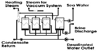
Fig. 6. A desalination design
In the case of vapor maintaining systems, it is worth noting
IJSER © 2012 http://www.ijser.org
International Journal of Scientific & Engineering Research, Volume 3, Issue 6, June-2012 4
ISSN 2229-5518
that producing vapor could be done in two ways:
1) A boiler which uses fossil fuel to maintain vapor with
desired conditions.
2) A boiler which uses hot gases from gas turbines (HRSG) to
maintain vapor with desired conditions.
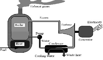
One of the disadvantages of gas turbines is their low efficiency which is between 30 to 40 percent. This means that ![]() of the energy of the used fuel is wasted by exiting hot gases. Exiting hot gases could be transferred to a regenerator boiler in order to use their potential heat energy to produce vapor. This vapor is the motive steam mentioned earlier. Also, a combined cycle and a desalination system could be coupled. In this way, the heat of the exiting gases of a gas turbine is used in a regenerator boiler to produce high-energy steam which is suitable to be used in a Rankin cycle. Because of the fact that the pressure of the produced vapor of the boiler is
of the energy of the used fuel is wasted by exiting hot gases. Exiting hot gases could be transferred to a regenerator boiler in order to use their potential heat energy to produce vapor. This vapor is the motive steam mentioned earlier. Also, a combined cycle and a desalination system could be coupled. In this way, the heat of the exiting gases of a gas turbine is used in a regenerator boiler to produce high-energy steam which is suitable to be used in a Rankin cycle. Because of the fact that the pressure of the produced vapor of the boiler is
Fig. 8. the principle of simple power plant
The first law of thermodynamics in a control mass indicates the relation between heat transfer and the work done. The general equation is [2], [12]:
very high, exiting pressure of the turbine is used which is ![]()
![]()
lower. In fact, the exiting pressure of the turbine should be![]()
adjusted in a way that the exiting pressure is compatible with ![]() the needs of the desalination system. Back pressure turbines
the needs of the desalination system. Back pressure turbines
(17)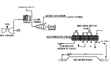
have the advantage of producing vapor with the necessary conditions [16].
Fig. 7. A combined Heat and Power System design
Combined Heat and Power systems consist of a power producing cycle including a gas turbine cycle and a steam turbine cycle. High-pressure and medium-pressure steams are produced in boilers and enter a two-pressured back pressure turbine and after doing axial work and expanding enter desalination system as the motive steam. Following that, the motive steam expands inside the TVC and condenses in the first heat recovery system and then goes to the heat regenerator boiler [2], [14].
![]() cyclic changes of work
cyclic changes of work
The second law of thermodynamics represents the efficiency and its equation is:
![]() (18)
(18)
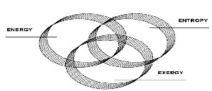
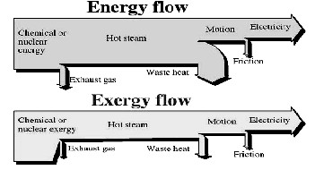
Fig. 9. interaction between relation of energy exergy and entropy
Fig. 10 exergy and energy flows through a thermodynamic system
IJSER © 2012 http://www.ijser.org
International Journal of Scientific & Engineering Research, Volume 3, Issue 6, June-2012 5
ISSN 2229-5518
Mass, energy, and exergy are extensive properties, and the![]()
![]()
following equations are written for a control volume [2], [3],
[10]: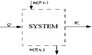
![]()
For steady state, exergy analysis is as follows:![]()
![]()
![]()
![]()
(27)
![]()
![]()
Fig. 11. an open system
(19) (20)
(21)
Exergy loss and destruction causes the system not to operate well. In the following equations, ![]() is the exergy of the exiting products, and
is the exergy of the exiting products, and ![]() is the exergy of the entering fuel stream [2].
is the exergy of the entering fuel stream [2].
1. Exergy destruction ratio of each part: The amount of exergy loss in that part divided by the exergy of the entering fuel stream![]()
![]()
(28)
![]()
![]()
![]()
![]() (22)
(22)
In which ![]() indicate physical exergy,
indicate physical exergy, ![]() indicates chemical exergy,
indicates chemical exergy, ![]() indicates kinetic exergy, and finally
indicates kinetic exergy, and finally ![]() indicates potential exergy. Chemical and kinetic and potential exergies could be neglected.
indicates potential exergy. Chemical and kinetic and potential exergies could be neglected.![]()
![]() (23)
(23)
![]()
![]()
![]()
![]()
2. The ratio of exergy destruction in each part divided by the total exergy loss in the cycle is defined as:![]()
![]() (29)
(29)
3. Both of the above equations are related to exergy destruction and are suitable for investigation the behavior of the cycle parts and show how efficient they are.
4. The ratio of exergy loss for each part: the amount of
exergy loss divided by the exergy of entering fuel![]()
stream
![]() the temperature of
the temperature of ![]()
![]()
![]()
![]()
![]()
(24)![]()
Exergy balance for steady state is:![]()
![]()
(30)
(31)![]()
![]()
![]()
![]()
![]() (25) (26)
(25) (26)
![]()
![]()
![]()
![]()
![]()
![]()
And exergy efficiency is expressed as:
(32)
The transferred energy by means of work, the transferred exergy![]()
Exergy efficiency (Efficiency of the second law) is used to
compare the similar parts that is an indicator of performance.
IJSER © 2012 http://www.ijser.org
International Journal of Scientific & Engineering Research, Volume 3, Issue 6, June-2012 6
ISSN 2229-5518
In this analysis, by considering the total entering exergy of the cycle, final specified exergy to each product is determined. In systems with more than one exiting product, each product must have a specific subsystem in which there are facilities specified for producing that product only [14]. Now, equations of the combined heat and power systems will be considered.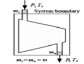
Fig. 13. A desalination schema
![]() (41)
(41) ![]()
![]() (42)
(42)![]()
![]()
![]() (43)
(43) ![]()
![]()
![]()
![]() (44)
(44)
Fig. 12. A schema of turbine
![]()
![]()
![]()
![]()
![]()
![]() (33)
(33) ![]() (34)
(34)
Turbine analysis and useful equations [1], [2], [3].![]()
![]()
![]()
![]()
![]()
![]()
![]()
![]()
![]()
![]()
![]()
For desalination we have [1], [2], [3]:
(35)![]()
(36) (37) (38)![]()
(39) (40![]()
![]()
![]()
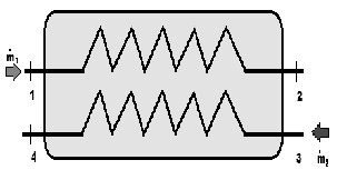
Fig. 14. A heat exchanger
Thermo-economy is a branch of science which represents an analysis of a system by combining exergy analysis with economic basics. Considering the fact that analytical equations of thermodynamic are based on exergy principle, the word
‚Exergoeconomy‛ is used. While designing a system, the
knowledge of final costs of the products for economic
efficiency is really useful. If just thermodynamic considerations are taken into account, the proposed design may be impossible to build, or the costs might be very high. A point of designing is looked for that both thermodynamic efficiency of the system is high, and the system is suitable from economic point of view. In this study, first, the thermo- economic index function will be formed. Then, optimizing with the aid of minimizing the rate of costs will be done. The way of defining index function depends on the conditions of each project [17], [18].
IJSER © 2012 http://www.ijser.org
International Journal of Scientific & Engineering Research, Volume 3, Issue 6, June-2012 7
ISSN 2229-5518
Temperature gradient in the heat rejection system is defined as the difference between the entering steam temperature and exiting sea water from heat rejection system which is assumed to be ![]() C.
C.
1. Temperature of the entering steam to the first heat recovery system:
2. The maximum value of this parameter could be ![]() C
C
because of sediment, and the minimum value of it can
be ![]() because of the disfunctioning of the vacuum ejector.
because of the disfunctioning of the vacuum ejector.
3. The temperature of the last heat recovery system, because of environmental limitations, can be between
48 and 37.
Climate conditions of the installation location-Performance specifications of a gas turbine in site conditions- Performance specifications of a steam cycle- Performance specifications of MED desalination device:
TABLE 1

Condition of Power System
unit cost of electricity($/KWH) 0.79 unit cost of water($/m³) 1.81 useful life(year) 20
capacity of each unite(ton/h) 1600 temperature of ambient 41 temperature of the last brine ?? Salt composition of sea water (%) 0.031
Salt composition of brine outlet (%) 0.05 motive steam flow(ton/h) 483 motive steam pressure ? number of effect 6?7 steam turbine performance parameter
HP steam flow rate(kg/s) 129.3
HP steam pressure (bar) 91
HP steam temperature (°c) 527
LP steam flow rate (kg/s) 17.2
LP steam pressure (bar) 52
LP steam temperature (°c) 247
exhaust temperature(°c) 135
IP pressure (Kpa) 1250
Efficiency (%) 74
GT model v92.4 turbine exhaust mass flow(kg/s) 521 turbine exhaust temperature(°c) 541 fuel mass flow rate(kg/s) 9.8
air flow rate(kg/s) 527
net power output(MW) 23.1
ambient temperature(°c) 28 ambient pressure(bar) 1.01
Relative humidity (%) 59 site elevation(m) 17
fuel LHV(kj/kg) 43718

The way in which exergy is divided in combined heat and power system shows that 50% of the potential entering exergy to the system disappears because of the irreversibility’s of combustion process in the gas turbine and the loss caused by HRSG chimney. 30% of that is transferred to the vapor part
loos exergy
allocated exergy to water
allocated exergy to power
system
Fig. 15 Distribution for exergy allocation
IJSER © 2012 http://www.ijser.org
International Journal of Scientific & Engineering Research, Volume 3, Issue 6, June-2012 8
ISSN 2229-5518
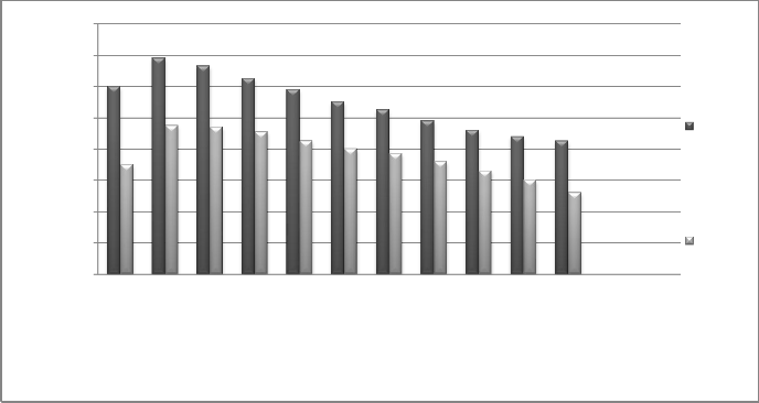
In the investigations, pressure is variable from 5bar to 20bar. Also, the number of heat recovery systems is considered to be
18
16
14
12
10
8
6
4
2
0
10 bar 12.5 bar 15 bar 17.5 bar 20 bar 22.5 bar 25 bar 27.5 bar 30 bar 32.5 bar 35 bar
6 effect
7 effect
Fig. 16 Effect of outlet pressure of turbine on amount of water
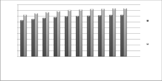
As it can be seen from the diagram, the amount of water production and it is cost increase by increasing the entering motive steam pressure to the desalination device.The reason why amount of water (GOR) increases is that increasing the pressure of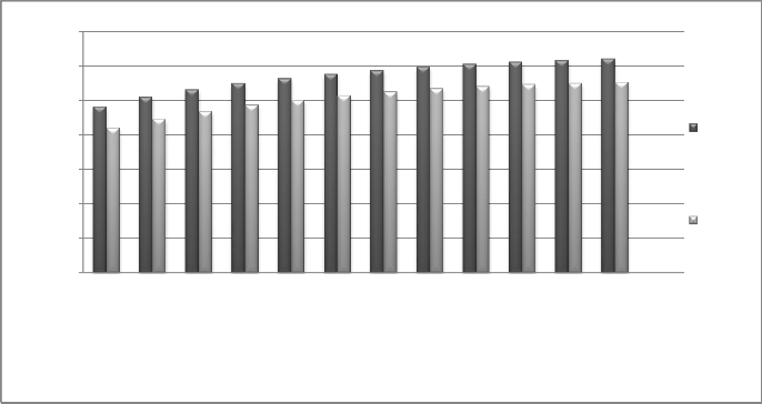
entering pressure results in higher static enthalpy of the entering steam which will result in higher vacuum at the nozzle of the ejector.
0.7
0.6
0.5
0.4
6 effect
0.3
0.2
0.1
7 effect
0
5bar 7.5 bar 10 bar 12.5 bar
15 bar 17.5 bar
20 bar 22.5 bar
25 bar 27.5 bar
30 bar 32.5 bar
35 bar
steam turbine backpressure
Fig. 17 Effect of outlet pressure of turbine on fuel cost
IJSER © 2012 http://www.ijser.org
INTERNATIONAL JOURNAL OF SCIENTIFIC & ENGINEERING RESEARCH, VOLUME 3, ISSUE 3, JUN-2012 9
ISSN 2229-5518
170
168
166
164
162
7effect
160
158
156
6 effect
154
5bar 7.5 bar 10 bar 12.5 bar
15 bar 17.5 bar
20 bar 22.5 bar
25 bar 27.5 bar
30 bar 32.5 bar
35 bar
steam turbine backpressure
Fig. 18 Effect of outlet pressure of turbine on total net benefit
Higher pressure needs more expensive evaporators which will increase the costs of initial investments. On the other hand,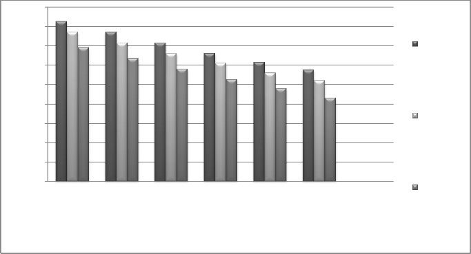
the exergy efficiency decreases, and the cost of fuel specified to water production increases. Taking everything into consideration, increasing the pressure of entering steam will result in higher water production costs.
18
16
14 20 bar(steam
12 back
pressure)
10
8
6
4
2
0
2.6°C 2.8°C 3°C 3.2°C 3.4°C 3.6°C 3.8°C
temperature difference at per effect (°c)
10 bar(steam back pressure)
5 bar9steam back pressure)
Fig. 19 Effect of temperature difference at per effect on amount of water
Increasing the number of heat recovery systems and decreasing temperature gradient between the stages results in increasing GOR. Diagrams show that the decrease of amount of water (GOR) has a linear relationship with the increase of
IJSER © 2012 http://www.ijser.org
INTERNATIONAL JOURNAL OF SCIENTIFIC & ENGINEERING RESEARCH, VOLUME 3, ISSUE 3, JUN-2012 10
ISSN 2229-5518
temperature. More heat recovery systems make bigger heat transfer surfaces in evaporators and as a result, the temperature gradient between the stages decreases.
120
100
80
20 bar(steam back pressure)
60
10 bar(steam
40 back
pressure)
20
0
2.6°C 2.8°C 3°C 3.2°C 3.4°C 3.6°C 3.8°C
Temperature diffrent at per effect (°c)
5 bar9steam back pressure)
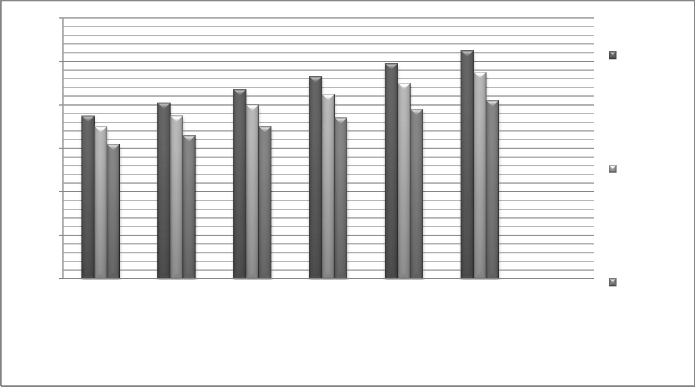
Fig. 20 Effect of temperature difference at per effect on exergy
Decreasing temperature gradient between the stages and also decreasing the pressure gradient between heat recovery systems decrease the exergy destruction and increase the performance and exergic efficiency.
From the obtained result, it could be found out that increasing the exiting pressure of the turbine will result in lower electricity production cost, rate of electricity production, and the income rate of electricity selling. In addition, increasing the number of heat recovery system increases the cost of electricity production, but the electricity production and the income rate of electricity selling decreases.
[1] Çengel, Y.A. , A .B. M ichael, ‚Thermodynamics An Engineering
Approach.‛ 6th Edn, McGraw Hill. Companies, Inc. New York . 2008. [2] Gordon Van Wylen, Richard Sonnatag, Claus Borgnakke
‘Fundamental of Classical Thermodynamics’ 4th Edn ,Michigan 1993. [3] Frank P. Incropera, David p. De Witt ‚Introduction to Heat Transfer‛
4th Edn.
[4] Franz Trieb ‚Combined Solar Power and Desalination Plants: Update
on the MED-CSD Project‛ IEA Paris, March 23, 2009.
[5] Cand. Wi-Ing , Frank Münk ‚Ecological and economic analysis of Sea water desalination plants‛ April 2008.
[6] SUMMARY REPORT: ‚Introduction to Desalination Technologies in
Australia‛ September 2002.
[7] Yantovski E. ‚WHAT IS EXERGY?‛, 2004.
[8] Masanori Shukuya ,Abdelaziz Hammache ‚Introduction to the
Concept of Exergy ‚April 25, 2002.
[9] Göran Wall, Mei Gong ‚EXERGY ANALYSIS VERSUS PINCH TECHNOLOGY‛ Stockholm, Sweden, June 25-27, 1996.
[10] Isidoro Martinez 1995-2012 ‚EXERGY‛.
[11] Bilal A. Qureshi and Syed M. Zubair ‚Application of exergy analysis to various psychrometric processes‛ Dhahran 31261, Saudi Arabia. 2003.
[12] Ibrahim Dincer , Yunus A. Cengel ‚Energy, Entropy and Exergy
Concepts and Their Roles in Thermal Engineering‛. August 2001. [13] Göran Wall ‚EXERGY AND SUSTAINABLE DEVELOPMENT‛
Mölndal, Sweden.
[14] Göran Wall ‚EXERGETICS‛ Bucaramanga 2009.
[15] H G Langeroudi, C Aghanajafi. ‚Thermodynamic ’ s Second Law Analysis for Laminar Non-Newtonian Fluid Flow‛. Volume: 25, Issue: 3-4, Publisher: Springer Science and Business Media Deutschland GmbH, Berlin, 14197, Germany, Pages: 165-173.
[16] Yongqing Wanga, Noam Liorb ‚Performance Analysis of Combined Humidified Gas Turbine Power Generation and Multi-Effect Thermal Vapor Compression Desalination System. 2006.
IJSER © 2012 http://www.ijser.org
INTERNATIONAL JOURNAL OF SCIENTIFIC & ENGINEERING RESEARCH, VOLUME 3, ISSUE 3, JUN-2012 11
ISSN 2229-5518
[17] El-Nashar, Ali M "Cost Allocation in a cogeneration plant for the productio n of power and desalted water comparison of the exergy cost accounting metho d with the VVE A method" 1999.
(18] Kamal, I. and Sims G. V "Thermal Cycle and Financial Mo deling"
1995.
(19] Dario Breschi "Overview on seawater Distillation Technologies
"Barcelona, 2005.
(20] NASHAR "Integration of seawater desalination with power generatio n"
[21] Y.M. El-Sayed, R.A Gaggioli "A Critical Review of Second Law
Costing Metho d", 1989.
[22] Langeroudi, H., Aghanajafi, C." Thermo dynamics Second Law
Analysis f or Laminar Non-Newtonian Fluid Flow". Journal of Fusion
Energy, Vol. 25, No. 3-4. (December 2006), pp. 165-173.
IJSER lb) 2012