International Journal of Scientific & Engineering Research, Volume 4, Issue 8, August 2013
ISSN 2229-5518
565
The Witricity: Revolution in Power Transmission
Technology
Mohammad Yasir Md. Shakibul Haque
Lecturer (Electrical Engineering) M. Tech. (Pursuing) University Polytechnic, Shahjahanpur Mechanical Engineering Integral University, Lucknow, India Invertis University, Bareilly, India
Abstract— Consumers of electric power always want fastest most, high efficient & faultless technology of power transmission everywhere. For this many concepts, research papers, patents are available on witricity but the market study of this commercial technology is yet to be materialized. Hence in order to provide them the same, we presented here the basic concept, background, complete evaluation and detailed study of this technology with its modern techniques. We also presented about all the available theories and prototypes. Besides of it here we also discussed the merits and de- merits with it’s available practical commercial and non commercial applications along with the recent development and researc hes in Market growth study and economic aspects.
Nikola Tesla is best known for his remarkable statements regarding the wireless transmission of electrical power. His first efforts towards this end started in 1891 and were intended to simply about this fact that object of his experiments was simply to produce effects locally and detect them at a distance.
Index Terms— W itricity, Microwave Power transmission (MPT), Nikola Tesla, Rectenna, W ireless Power transmission (W PT), Lunar, Tesla tower, Tesla Coil, Energy Information Agency (EIA), Solar Power
—————————— ——————————
1 INTRODUCTION
itricity may be defined as the way of efficient transmis- sion of electric power from one point to another through vacuum or atmosphere without use of wire or
any other substance which make a physical connection. It is not a new idea. Many researchers developed several methods for wireless power transmission. About hundred years ago witricity was the dream of Nikola Tesla. He tried to transfer
300kW power through 150 kHz radio wave[1,2], but unfortu- nately he failed due to diffusion of wireless power. After this failure the same concept is focused on wireless communica- tion & got great success.
As per the requirement to introduce new terminology for eve-
ry new technology and also habitual an familiarize with this. The researchers of current century coined the term witricity; which is basically derived from wireless electricity. So now the scenario of wireless power transmission (WPT) & Microwave Power Transmission (MPT) is completely changed into the Witricity or Witrics.
The inventors in Massachusetts Institute of Technology
(MIT) have devised a means of providing electricity without
————————————————
• Mohammad Yasir is a Lecturer in Department of Electrical Engineering at
Integral University, Lucknow, India, PH-09451918907
E-mail: yasir.banda@gmail.com
• Md. Shakibul Haque is currently pursuing masters degree program in
Mechanical Engineering in Invertis University, Bareilly, India, PH-
09369223741. E-mail: mdshakibulhaque@rediffmail.com
any wires. This technology is based upon the coupled resonant objects in which resonant magnetic fields are used. So the wastage of power is reduced. The system consists of witricity
transmitters and receivers. The transmitters and receivers con- tain magnetic loop antennas made of copper coils and they are tuned to the same frequency. It is with the help of resonant magnetic fields that witricity produces electricity, while reduc-
ing the wastage of power. This modern technique is unlike the
IJSER © 2013 http://www.ijser.org
International Journal of Scientific & Engineering Research, Volume 4, Issue 8, August 2013
ISSN 2229-5518
566
principle adopted by Nikola Tesla in the later part of the 19th century; where conduction based systems were used.[16]
In order to evaluate this technology various methods are tried
for development of witricity in which some are only theories, some are only prototypes and some are ready to use. The common approaches to get witricity as per survey report [10] of University of Belgrade, Serbia in December 2011 are:
i. Radio-wave transmission
ii. Electromagnetic induction/Magnetic resonance iii. Capacitive coupling
iv. Laser/infrared optics transmission
v. Microwave
Here second method is more convenient easy and environ- ment friendly hence in new age it is soul of this technology.
2 ABOUT THE TECHNOLOGY
2.1 Background
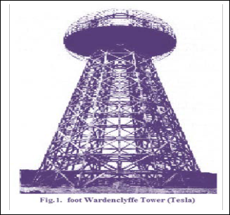
The idea of transmitting power through the air has been around for over a century, with Nikola Tesla’s pioneering ide- as and experiments [5]. In 1899 when he researched on EM radiations he found that EM radiation can propagate over a large distance more than 200 miles around the globe in earth cavity by adding it in parenthesis through Tesla tower [11,12]. Hence he proved that the wireless propagation of electrical power is possible and a feasible alternative to the extensive in place of costly grid of electrical transmission lines used today for electrical power distribution. Although he failed due to breakdown in transmission and unable to stand in commercial market but modern scientific theory and mathematical calcula-

tions supported his experiment.
First NASA solar powered satellite 1958
Oil Crisis
NASA program
Marine Soijacic and his team [20]– Experimented in 2007
60-watt light bulb from a power source 7 feet away without wires. [20]
Currently looking for Witricity in the range of 100
watts.
2.3 Concept to The Technology
Basic idea of inductive coupling is parallel to the mechanical resonance in which the oscillation frequency of two different identical system matched for the example lets think about the vibration of glass window if one vibrate then the identical glass also starts vibrating, or if one pot in the kitchen vibrate then another identical pot starts vibrating with same frequen- cy. The same concept is used here in electrical oscillator. We make two identical electrical pendulum when one starts oscil- late than other identical pendulum tank circuit start vibrate with same frequency this device works not only as receiver but also transmitter [3,4]. This is known as inductive coupling. It can also be used as a rectifying antenna or Rectenna.[19]
In this Rectenna oscillates at the resonant frequency between the inductor (energy stored in the magnetic field) and the ca- pacitor (energy stored in the electric field) and is dissipated in the resistor. The individual resonant frequency and the quality factor for this resonator are [26,27]

ω = 1 ------------- (1)
C
ω0 L 1
ω0 L
At that time it was also proved by W. Brown and other scien- tist in different experiments of that age that this wireless trans- fer of high frequency electricity signals by several techniques such as Microwave transmission, Optical transmission & Laser Transmission etc are also possible over a large distance. How- ever, similar caveats about safety and system complexity ap- ply for these radiative approaches.
After this age all the scenario has been focused on wireless communication and got a great success. But there was not any focus on wireless transmission of electricity for a long period. Suddenly in 2007 the team of reviver in MIT (Messachucssets Institute of Technology, Cambridge, NY.) of this technology reviewed with the extensive effort and leadership of Marine Soijacic by glowing 60 watt bulb at a distance of 2 meter [13,20]. Now the team is currently looking same for 100watt.
2.2 Brief History
Nikola Telsa – Experimented in 1899
Imagined a global wireless power distribution system
William Brown
Established microwave to electricity conversion
Invention of the Solar Panel


Q = = � =
2Γ C R R
------------- (2)

IJSER © 2013 http://www.ijser.org
International Journal of Scientific & Engineering Research, Volume 4, Issue 8, August 2013
ISSN 2229-5518
567
The expression for Q (i.e. equation 2) shows that decreasing the loss in the circuit, i.e., reducing R, increases the quality
sistance values). If we choose
factor of the system. In highly-resonant wireless power trans- fer systems, the system resonators must be high-Q in order to efficiently transfer energy. [22] High-Q electromagnetic reso-

Rg
RL.

= RL
Rd.

= �1 + U2
nators are typically made from conductors and components
with low absorptive (also sometimes referred to as ohmic, re-
sistive, series resistive, etc.) losses and low radiative losses,
and have relatively narrow resonant frequency widths. Also, the resonators may be designed to reduce their interactions with extraneous objects.
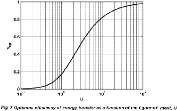
then the efficiency of the power transmission is maximized and is given by

U2
ŋopt = 2 − − − −(4)
�1 + √1 + U2 �
Here one can see that highly efficient energy transfer is possi-
ble in systems with large values of U . Note that the imped-
ance matching described above is equivalent to the coupled
mode theory treatment that shows that work extracted from a
device can be modeled as a circuit resistance that has the effect of contributing an additional term, Γw, to an unloaded device object’s energy loss rate Γd, so that the overall energy loss rate is given by
Γ�d=Γd+Γw − − − − (5)
and that the efficiency of the power transmission is maximized
when


For resonant coupled system here the generator is a sinusoidal Γw 2 2 2

voltage source with amplitude Vg at frequency ω with gener- ator resistance Rg. The source and device resonator coils are
= �1 + k /ΓsΓd = �1 + k QsQd = √1 + U
Γd
− − − (6)
represented by the inductors Ls and d Ld which are coupled

through the mutual inductance M, where M= k�Ls Ld . Each
coil has a series capacitor to form a resonator. The resistances
Rs and Rd are the parasitic resistances (including both ohmic
and radiative losses) of the coil and resonant capacitor for the
respective resonators. The load is represented by an equiva-
lent AC resistance RL. Analysis of this circuit gives the power
delivered to the load resistor, divided by the maximum power available from the source when both the source and device are resonant at ω.
U2 Rg RL
Note that the best possible efficiency of a wireless power transmission system only depends on the system figure-of- merit, which can also be written in terms of the magnetic cou- pling coefficient between the resonators, k , and the unloaded resonator quality factors are Qs and Qd .[22]
3 THE NEED FOR A WIRELESS SYSTEM OF ENERGY
TRANSMISSION
A great concern has been voiced in recent years over the ex- tensive use of energy, the limited supply of resources, and the pollution of the environment from the use of present energy


PL =
Pg.max.
R g
��1 +

Rs Rd
R L
− − − (3)
2
conversion systems. Electrical power accounts for much of the
energy consumed. Much of this power is wasted during
Where
Rs � �1 + Rd � + U �
transmission from power plant generators to the consumer.
The resistance of the wire used in the electrical grid distribu-
tion system causes a loss of 26-30% of the energy generated.
This loss implies that our present system of electrical distribu-


ω M k
U = = = k�QsQd
tion is only 70-74% efficient.
A system of power distribution with little or no loss would
�RsRd
�ΓsΓd
conserve energy. It would reduce pollution and expenses re- sulting from the need to generate power to overcome and
is the figure-of-merit for this system.
We have the ability to choose the generator and load re- sistances which give the best system performance (or use an impedance transformation network to match to other re-
compensate for losses in the present grid system.
The proposed project would demonstrate a method of energy
distribution calculated to be 90-94% efficient. An electrical
distribution system, based on this method would eliminate the
need for an inefficient, costly, and capital intensive grid of
IJSER © 2013 http://www.ijser.org
International Journal of Scientific & Engineering Research, Volume 4, Issue 8, August 2013
ISSN 2229-5518
568
cables, towers, and substations. The system would reduce the cost of electrical energy used by the consumer and rid the landscape of wires, cables, and transmission towers.
There are areas of the world where the need for electrical power exists, yet there is no method for delivering power. Af- rica is in need of power to run pumps to tap into the vast re- sources of water under the Sahara Desert. Rural areas, such as those in China, require the electrical power necessary to bring them into the 20th century and to equal standing with western nations.
As first proposed by Buckminster Fuller, wireless transmission
of power would enable worldwide distribution of off peak
demand capacity. This concept is based on the fact that some
nations, especially the United States, have the capacity to gen-
erate much more power than is needed. This situation is ac- centuated at night. The greatest amount of power used, the peak demand, is during the day. The extra power available during the night could be sold to the side of the planet where it is day time. Considering the huge capacity of power plants in the United States, this system would provide a saleable product which could do much to aid our balance of payments.
4 MARKET ANALYSIS
About 56 billion dollars spent for research by the U.S
government in 1987, 64% was for military purposes and only
8% was spent on energy related research. More efficient energy distribution systems and sources are needed by both developed and under developed nations. In regards to Project Tesla, the market for wireless power transmission systems is enormous. It has the potential to become a multi-billion dollar per year market.[6,7]
could expect an even faster rise in the demand for electrical power in the near future.[6]
In 1971, nine industrialized nations, (with 25 percent of the world's population), used 690 million kilowatts, 76 percent of all power generated. The rest of the world used only 218 mil- lion kilowatts. By comparison, China generated only 17 mil- lion kilowatts and India generated only 15 million kilowatts (less than two percent each). If a conservative assumption was made that the three-quarters of the world which is only using one-quarter of the current power production were to eventual- ly consume as much as the first quarter, then an additional 908 million kilowatts will be needed. The demand for electrical power will continue to increase with the industrialization of the world.[8]
4.2 Market Projections
The Energy Information Agency (EIA), based in Washington, D.C., reported the 1985 net generation of electric power to be
2,489 billion kilowatt hours. At a conservative sale price of
$.04 per kilowatt hour that results in a yearly income of 100
billion dollars. The EIA also reported that the 1985 capacity
according to generator name plates to be 656,118 million
watts. This would result in a yearly output of 5,740 billion kil-
owatt hours at 100% utilization. What this means is that we
use only about 40% of the power we can generate (an excess capability of 3,251 billion kilowatt hours).[8]
Allowing for down time and maintenance and the fact that the night time off peak load is available, it is possible that half of the excess power generation capability could be utilized. If
1,625 billion kilowatt hours were sold yearly at $.06/kilowatt, income would total 9.7 billion dollars.[7]
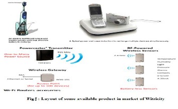
4.3 WiTricity Products
WiTricity’s wireless power transfer technology can be applied in a wide variety of applications and environments. The ability of our technology to transfer power safely, efficiently, and over distance can improve products by making them more convenient, reliable, and environmentally friend-
ly. WiTricity technology can be used to provide:
4.1 Market Size
• Direct Wireless Power—when all the power a device needs is provided wirelessly, and no batteries are required. This mode is for a device that is always used within range of its WiTricity power source.[23]
• Automatic Wireless Charging—when a device with recharge-
able batteries charges itself while still in use or at rest, without requiring a power cord or battery replacement. This mode is for a mobile device that may be used both in and out of range of its WiTricity power source.[22]
WiTricity technology is designed to be directly embedded in
The increasing demand for electrical energy in industrial na- tions is well documented. If we include the demand of third world nations, pushed by their increasing rate of growth, we
the products and systems of Original Equipment Manufactur-
ers (OEM's). If your company is an OEM, you may be interest-
ed in our development kits which will allow you to evaluate
and adapt WiTricity wireless power transfer to your own
IJSER © 2013 http://www.ijser.org
International Journal of Scientific & Engineering Research, Volume 4, Issue 8, August 2013
ISSN 2229-5518
569
products, or you may prefer a custom.
5 MERITS & DEMERITS OF WITRICITY
5.1 Merits of Witricity
1. 1. Wireless Power Transmission system would completely eliminates the existing high-tension power transmission line cables. In spite of it power transmission can be possible if there is any obstruction like wood, metal, or other devices were placed in between the transmitter and receiver.
2. 2. Witricity replaces the use of power batteries, Substation
and power grid.
3. 3. Witricity does not follow any path of resistive wire hence
neither energy absorbed nor dissipated hence there is negligi- ble wastage so it has highly efficient.
4. 4. There is no wire or transmission cable in witricity hence no possibility of power failure or power theft in it.
5. By the use of resonant coupling wave lengths produced are far
lower and thus not produce any negative effect to the health as well as environment.
6. Due to complete elimination of costly transmission line cables, substations and grid etc by the cheaper components of transmitter and receivers, the system is less costly.
7. The problem of electricity, especially in rural or other areas where is no method for delivering power trough transmission line due to cost and location will surely solve through witrici- ty.
5.1 Demerits of Witricity
1. Efficiency is only about 40%.As witricity is in develop- ment stage, lot of work is done for improving the effi- ciency and distance between transmitter and receiver.
2. The Capital Cost for practical implementation of WPT
seems to be very high.
3. The occurring of interference of microwave with pre- sent communication systems which causes huge noise in both.
4. If we use microwave in this technology it will pro-
duce wrong Biological Impact.
4 CONCLUSION
It is now a reality that electrical energy can be economical- ly transmitted without wires to any terrestrial distance. This technology would reduce the cost of electrical energy for consumers and get rid of the landscape of wires, cables, and transmission towers etc. It has negligible demerits which was found insignificant and biologically compatible. Now a days Witricity is in developing stage[24], lots of work is to be done to use it for wireless power applications. So Witricity has a large scope in electrical engineering for future prospects of power generation and transfer. It has a great economic impact to human life. Many countries will get benefited by this service. Monthly electric utility bills from old- fashioned, fossil-fuelled, loss prone electrified wire-grid delivery services will be optional, much like ―cable TV of today.
It is recognized by market analysis and study of this research that wireless power is making the transition from a technology to an industry – products are commercially available, and a wireless power standard is evolving. In the near term, more products will be adopted and accepted by consumers. And, though the real stability of any one technology can be defined as a solution that allows the most flexibility through multiple commercial applications while meeting consumer expecta- tions, the ultimate scenario is for the best solutions to meld together as wireless power as a whole evolves. As scenarios continue to play out and the industry continues to be de- fined, there are several key considerations that need to be fully explored. The various methods and aspects regarding wireless transmission of electrical power have been listed. The evolution of the technology from the time of Tesla has been overviewed with the basic concept, background, and detailed study of this technology with its modern technique.
ACKNOWLEDGMENT
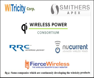
The authors wish to thank all of the companies which provide us all the useful data for our important market analysis & sur- vey. We also like to wish to our students and couleges who gave us valuable suggestions regarding this paper. And we deeply thanks to our parents for their kind moral support.
References
[1] Nikola Tesla, “The Transmission of Electrical Energy Without Wires as a Means for Furthering Peace,” Electrical World and Engineer. Jan. 7, p. 21, 1905.
[2] N.Tesla of NY invented “Mthods of utilizing energy”, U.S. PATENT OFFICE, Patent no. 685,958, Patented on 5 Nov. 1901,application filed on 21 March, 1901, S.N. 52,154
[3] Walker, J., Halliday, D., & Resnick, R. (2011). Fundamentals of phys- ics. Hoboken, NJ: Wiley.
[4] Hu, A. P. (2009). Wireless/Contactless power supply: Inductively coupled resonant converter solutions. Saarbrücken, Germany: VDM Verlag Dr. Müller.
[5] Valone, T. (2002). Harnessing the wheelwork of nature: Tesla's sci-
IJSER © 2013 http://www.ijser.org
International Journal of Scientific & Engineering Research, Volume 4, Issue 8, August 2013
ISSN 2229-5518
570
ence of energy. Kempton, Ill: Adventure Unlimited Press. [6] http://witricity.com/
[7] www.wirelesspowerconsortium.com
[8] http://witricitypower.com/
[9] http://electronics.howstuffworks.com/wireless-
power.htm
[10] A Survey on wireless power transmission methods (December 2011) by Department of Computer Science, Faculty of Mathematics Univer- sity of Belgrade, Serbia.
[11] http://en.wikipedia.org/wiki/Wireless_energy_transfer
[12] http://en.wikipedia.org/wiki/Wireless_power
[13] "Goodbye wires". MIT News. 2007-06-07.
http://web.mit.edu/newsoffice/2007/wireless-
0607.html.
[14] International Journal of Emerging Technology and Advanced Engi- neering ISSN 2250-2459, Volume 2, Issue 4, April 2012
[15] Wireless Power Transmission – A Next Generation Power Transmis- sion System ©2010 International Journal of Computer Applications (0975 – 8887) Volume 1 – No. 13
[16] X. Yu, S. Sandhu, S. Beiker, R. Sassoon, and S. Fan, “Wireless energy
transfer with the presence of metallic planes”, Applied Physics Let- ters 99, 214102 (2011). U. S. Provisional Patent Application
61/542,667, filed 10/3/2011.
[17] Wireless Power Transmission for Solar Power Satellite- @ AKGEC JOURNAL OF TECHNOLOGY, vol.1, no.2
[18] Tesla, N., “The transmission of electric energy without wires”, Elec- trical World, March 5, 1904
[19] UNDERSTANDING WIRELESS POWER © 2009 Fulton Innovation
LLC
[20] Aristeidis Karalis, J.D.Joannopoulos, and Marin Soljacic (2006). “Wireless Non-Radiative Energy Transfer.
[21] AcuPOLL® Research, Inc., August 2008 “Project Alamo River”
[22] “Highly Resonant Wireless Power Transfer: Safe, Efficient, and over Distance” by Dr. Morris Kesler WiTricity Corporation ©WiTricity Corporation, 2013
[23] “Wireless power Transmission: Applications and Components ..” International Journal of Engineering Research & Technology (IJERT) Vol. 1 Issue 5, July – 2012 ISSN: 2278-0181
[24] SasthraKeralam magazine, India
[25] www.howstuffworks.com
[26] Fundamentals of electrical engineering by Ashfaq Hussain, Dhanpat
Rai & company. (3rd Edition)
[27] Electrical Engineering Fundamentals by Vincent Del Toro, Pearson
Edu. Inc. New Jersey 07485, U.S.A.
IJSER © 2013 http://www.ijser.org