
International Journal of Scientific & Engineering Research, Volume 6, Issue 4, April-2015 1249
ISSN 2229-5518
The Regenerative Energy Suspension System
Gaurang Tiwari, Dr. R.K. Saxena
Abstract-The amount of energy dissipated in the suspension system has brought several studies to harness the energy that was considered to be a waste previously. The factor affecting the harness of this energy is elaborated. The remedies are enlisted to overcome the issues. Few suspension system’s researches are reviewed. The paper concludes with a proposed system. Experimental results of the model are elaborated. Further, the outcomes are enlisted with future directions for applications ahead. Thereby the objective of this paper is to reveal the application of the suspension system to supply the vibration (mechanical) energy back to the battery system by converting it into electrical energy.
Index terms- Buck boost converter, Filters, Harmonics, Induced Voltage, Regulated Voltage, Rectifier, Ripples.
—————————— ——————————
About a decade ago, comfort was taken as a profound criteria & efficiency was overlooked to an extent. Today, no matter it be the commercial or the luxury vehicles there is a separate index to scale the efficiency. Is the amount of energy absorbed by the shock absorber of important concern? According to reference [1], only 10-20 % the fuel energy is used for vehicle mobility i.e. to overcome the friction from road resistance and air drag. One of the important losses is the energy dissipation is in suspension vibration..
FIGURE 1. VEHICLE ENERGY FLOW S OF A 2.5L 2005 CAMRY ( BANDIVADEKAR ET AL., 2008).
Hereby, this is quite clear that the efficiency of the automobiles has to be improved. The question again is how?? Well there can be several technological implementations to accomplish the purpose. Is the amount of energy absorbed by the shock absorber of an important concern? It surely is.
The amount of energy that can be harnessed from the vehicle suspensions depends on various factors. Velinsky et al. [2] concluded that the dissipated energy by suspension damper is related with
(A). ROAD ROUGHNESS (CLASS OF ROAD)
IJSER © 2015 http://www.ijser.org
International Journal of Scientific & Engineering Research, Volume 6, Issue 4, April-2015 1250
ISSN 2229-5518
(B).VEHICLE SPEED,
(C).SUSPENSION STIFFESS AND DAMPING COEFFICIENT
(D). VEHICLE LOAD (TONNAGE).
Interestingly, it even depends on the traffic. How?? The sudden acceleration and braking enables high contraction and expansion of the suspensions. On the other hand, how much energy we can extract from vehicle suspension? Suda et al. [4] proved that the harvested energy in the regeneration process is enough to meet the energy requirement in consumption process for electromagnetic active suspensions, which means the suspension is self- powered. The estimation by h su [5] indicated the average regenerative power of each suspension for gm impact running on the highway at 16 m/s reached 100w accounting for about 5% of driving power. F. Yu et al. [6] compared the energy consumption of passive and active suspension of car. Their simulation, under the conditions that the vehicle speed was 20m/s, the road roughness was class c, the simulation time was 20s, indicated that energy consumption of passive suspension is 651 KJ, while 645 kj for active suspension which decreased the RMS of sprung mass acceleration by 50%. Segel et al. [3] analyzed the energy dissipation of dampers of passenger vehicle, and shown that the total power of four dampers was about
200w when running on a poor road at the speed of 13.4m/s.
These data indicate that the energy dissipation of vehicle suspension can’t be ignored. If the suspension vibration energy can be recycled, the energy consumption of active suspension will be reduced significantly. Theoretical results show a maximum of 10 % fuel efficiency can be recovered from vehicle suspension system by implementing regenerative shock absorbers [1].
Thus the above evidences of research works reveal that the energy from the suspension system is substantial and cannot be overlooked.![]()
• Gaurang Tiwari, BE (Hons) in Electrical Engineering from SGSITS Indore, India. E-mail:gtgaurangtiwari@gmail.com
• Dr. R.K. Saxena, Professor & HOD, Electrical Engineering
Department, SGSITS Indore, India
4 PROPSED MODEL
The main idea of the proposed system depends on recovering this dissipated power, convert it into regulated
power using the applications of power electronics and then use it in battery charging or feeding some vehicle electric loads directly.
The operating principle is derived from the lenz law that states the change in flux in a coil produces an EMF.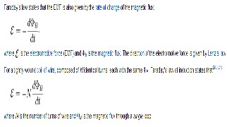
2 CONSTRUCTION
Method1: here the permanent magnets with high permeability are incorporated in the moving parts of the suspensions known as ‘shock absorber‘ where as the coils those are to be used to collect energy from the voltage induced are is wounded on ‘coil spring‘. Thus we have both the magnetic field and motion that produces the change in the magnetic flux in the coil readily producing an emf.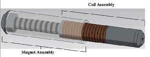
FIG.2 THE SUSPENSION ASSEMBLY
Method2: we can use of electromagnetic circuit rather than the use of permanent magnet. Here a magnet field will be produced perpendicular to its motion. Serving the same
purpose with pros and cons in either ways.
IJSER © 2015 http://www.ijser.org
International Journal of Scientific & Engineering Research, Volume 6, Issue 4, April-2015 1251
ISSN 2229-5518

(A) CHALLENGES
1. Deterioration of magnetic strenght:
The strength of the permanent magnet deteriorates with time. Hence, the use of permanent magnets is probably not a good option keeping in mind the timely replacement of magnets a tedious and unusual practice.
2. Complexity in circuit
The electromagnets used in method 2 are surely a better option as it eradicated the drawbacks of
permanent magnet. Though one has to keep in mind the reduction in complexity of electronic circuits as these would be in regular influence of vibrations. So the fabrication has to be reliable.
3. Irregularities in the voltage profile
The most important and tedious problem is that the instantaneous-generated voltage directly depends on the vibration/motion of the suspension system that induced from the road roughness (or acceleration
&braking). So, this power/voltage has a random instantaneous value at every interval, the voltage in this form is not valid for electric utilities as the vehicle load are designed to operate at a definite voltage(12v&24v) depending on the battery used for operation. Thus, this induced voltage has to be regulated for further applications. The proposed system eradicates this problem which perhaps is the lifeline of the system.
(B) REMEDIES
The next phase of the paper will elaborate the conversion of unregulated output to the regulated one. A single-phase bridge rectifier is used for rectification purposes. But this output contains ripples of this rectified voltage as shown in fig. 4. Also, this dc voltage has a random value. So, applied control schemes would regulate the voltage to the rated charging voltage of the battery. There are only three expected states for this dc-voltage: less, equal or greater than the charging rated voltage. So, a boost converter with control circuit is used to serve this purpose. The study of each unit is elaborated in the paper with block – in details –
of the overall proposed system shown in fig.3.
The input to the full wave rectifier is the output voltage at the terminals which is not regulated.
FIG.3
(C) OPERATING PRINCIPLES OF BOOST CONVERTER

(Ref 8) the boost converter has the advantages of being most adopting standards, economical as it has minimum number of switching devices with high efficiency and its dc output voltage is controlled. The boost converter shown in fig. 3 has a control loop which controls the output dc voltage, in this control loop the actual output dc voltage vs is compared to a reference voltage Vref. The output of this comparator is the output voltage control loop error. This error is passes through a voltage controller. Then, the output of this controller is compared with a triangular waveform to produce the pulse width waveform of the boost switch.
IJSER © 2015 http://www.ijser.org
International Journal of Scientific & Engineering Research, Volume 6, Issue 4, April-2015 1252
ISSN 2229-5518
FIGURE3: BOOST CONVERTER
When the boost switch Sb is turned on, the inductor current Iin through the boost switch builds up, and energy is stored in the magnetic field of the boost inductor lb. The boost diode Db is reverse biased and the boost capacitor Cb supplies power to the load. When the boost switch is turned off, the power circuit changes mode, and the stored energy in the boost inductor as well as the energy coming from the source is supplying power to the output circuitry which consists of the capacitor and the load.
The boost converter design includes two parts. The first is the power circuit that includes mainly the boost inductor and capacitor. The second part is the controls circuit which comprising the input current wave shaping and controlling the output dc voltage
5 STATISTICS OF THE RESULT
For a vehicle load of 15 ton, there is a difference between the vehicle load on the front axle & the rear axle. Taking a loaded condition of the vehicle, the average load is 2.5 tones on the front axle and 4 tones on the rear. On the rig testing we get the results of virtual vehicle. The frequency of motion for suspensions is 1.7-1.9hz in the front & 1.9-2hz
in the rear (it shows a strong variance with load).
The result of the variation of the voltage between the range states the experimental success. But further implementation needs a regulated voltage. Similar voltage profile was observed in (Ref 7), Electronic Research Institute Egypt. The statistics and data are shown. The power electronic circuit used in the later stage is the same. Though the initial stages of vibration energy conversion differs where they have used a linear generator.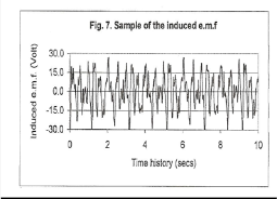
FIG 4
10
5
0
0.1 0.4 0.7 1 1.3 1.6 1.9 2.2 2.5 2.8 3.1 3.4 3.7 4
-5
-10
TIME (SEC)
FIG 5
VARIATION OF INDUCED EMF WITH TIME
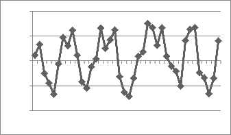
Thus the induced voltage varied between the range of -7.5 to +7 volts. The voltage being unregulated has to be employed to a conversion circuit to enable relevant applications. The conversion techniques are elaborated in
the remedies of the proposed model.
6 VALIDATION TO THE RESULT
IJSER © 2015 http://www.ijser.org
International Journal of Scientific & Engineering Research, Volume 6, Issue 4, April-2015 1253
ISSN 2229-5518
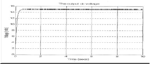
FIG 6
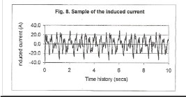
From the ref of (7) the induced Electro-Motive Force is shown in fig.4 in which the peaks harmonics from -25 to 25 volts which is not regulated, the peaks values of induced current shown in fig. 5 is fluctuating from -30 to 30 amp. Fig. 6 shows the final output voltage waveform that gives a voltage that is regulated, which is fluctuated around 15 volt, such this power with this voltage can be used to support some electric loads in the vehicle. Several various rating of converters are available to meet the regulation techniques.
ALTERNATIVE
LTC 3789 EGN buck-boost converter
The LTC®3789 is a high performance buck-boost switching regulator controller that operates from input voltages above, below or equal to the output voltage. The constant- frequency, current mode architecture allows a phase- lockable frequency of up to 600 KHZ, while an output current feedback loop provides support for battery charging. With a wide 4v to 38v (40v maximum) input and output range and seamless, low noise transitions between operating regions, the LTC3789 is ideal for automotive, telecom and battery-powered systems (Ref 9).
7 OUTCOME
The output voltage varied between the range of -7.5 volts to
7 volts with some instantaneous peaks also reaching a value upto 16 volts. This helps us to harness the electrical energy from the suspensions.
8 CONCLUSION & FUTURE DIRECTIONS
The energy harnessed is unregulated and on the applications of rectifiers too it will have uncertain harmonics. The article proposed enables the regulated output. Thus it can be concluded that the model can supply vehicle load though supplying directly to the battery may require further extension of filters if necessary to suppress harmonics. . It is strongly recommended to take the size and installation of regulating unit into consideration. The unit is liable to mechanical damage as it may encounter heavy vibrations since it would be installed near the suspension system. Though, good packaging can prevent this concern. Regressive charging & discharging of the battery may deteriorate its life. Thus it is also recommended that the output should be preferably used to operate vehicle loads directly rather than feeding the battery.
This work can be used as a benchmark & extensive study can be done to bring enhancement on this model for further development.
ACKNOWLEDGMENT
I wish to thank Dr. R.K. Saxena & Dr. B.M. Sharma. It was with their supreme surveillance and support that I have accomplished this research work which can be used for the development & innovations in POWER AND ENERGY STUDIES globally.
REFERENCES
[1] Pei s.z., “design of electromagnetic shock absorbers for energy Harvesting from vehicle suspensions”, master degree thesis, stony Brook university, 2010.
[2] Velinsky, Steven a. And white, Robert a, “vehicle energy dissipation Due to road roughness”, vehicle system dynamics, 1980, 9:6, pp. 359-384.
[3] Segel l, Lu x p, “vehicular resistance to motion as influenced by Road roughness and highway alignment”, Australian road research, 1982, 12(4), pp. 211-222.
[4] Nakano k, Suda y, et al., “application of combined type self Powered active suspensions to rubber-tired vehicles”, JSAE annual Congress, 2003, 6, pp. 19-22.
IJSER © 2015 http://www.ijser.org
International Journal of Scientific & Engineering Research, Volume 6, Issue 4, April-2015 1254
ISSN 2229-5518
[5] h su p, “power recovery property of electrical active suspension Systems”, proceedings of the inter society energy conversionEngineering conference, Washington DC, USA: IEEE, 1996,pp. 1 899-1 904.
[6] f. Yu, m. Cao, X.C. Zheng, “research on the feasibility of vehicle Active suspension with energy regeneration”, journal of vibration and Shock, 2005, 24(4), pp. 27-30. (in chinese)
[12]. Essential principles of physics, p.m. whelan, m.j. hodgeson, 2nd edition, 1978, john murray, isbn 0-7195-3382-
1
[13]. Nave, carl r. "faraday's law". Hyperphysics. Georgia state university. Retrieved 29 august 2011.
(14)Professor Lei Zuo, Brian Scully, Jurgen Shestani, and Yu
Zhou, all mechanical engineers from the state university of
New York
(7) A.M.A. Abouelnour, n. Hammad Electrical engineering department, faculty of engineering, Helwan University, Cairo, Egypt
(8) A.E. Essamudin Electronics Research Institute, Egypt) (10).Zhang Jin-qiu, Peng Zhi-Zhao*, Zhang Lei, Zhang Yu,
proceedings of the world congress on engineering 2013 vol
iii, Wce 2013, july 3 - 5, 2013, London, U.K.
(9)Peng Li, Chongxiao Zhang, Junyoung Kim, Liangyao yu, Lei Zuo Stony brook Univ. (United States)
(11)Lei Zuo and Xiudong Tang
(16) wikipedia
IJSER © 2015 http://www.ijser.org