
The dual open-end stator winding induction machine is fed by four voltage inverters as shown by the figure 1. Each inverter is dimensioned to a quarter power of the machine.
International Journal of Scientific & Engineering Research, Volume 4, Issue 7, July-2013 640
ISSN 2229-5518
The Dual Open-End Winding Induction Machine
Fed by Quad Inverters in Degraded Mode
Sami Guizani, Faouzi Ben Ammar
Abstract— In this paper, the different failed inverters for the feeding dual open-end stator winding induction machine is proposed. Each input of open-end stator winding is supplied by one three phase voltage source inverter. The different conditions must be respect after first, second and third failure in four inverters feeding the machine are presented.This study shows the advantage of the dual open-end stator winding induction machine to improve the availability of service of a variable speed drive.
Index Terms— Availability, Dual open-end stator winding induction machine, Failed inverter, Operation degraded mode, Three phase 2- level inverter.
————————————————————
He improvement availability, reliability and the power segmentation of the speed drive application became an essential purpose for the industrialization of the high
power equipment.
The concept of PEBB (Power Electronic Bulding Block)
initiated by the ONR (Office of Research Noval) and CPES
(USCenter of Power Electronics System), aims to improve
reliability, modularity, standardization, reconfigurability

The dual open-end stator winding induction machine is fed by four voltage inverters as shown by the figure 1. Each inverter is dimensioned to a quarter power of the machine.
Inverter A1 Inverter A2
scalability and the cost of electrical systems in many fields
such as railways applications, aeronautics, electrical
propulsion of ships and electrical vehicles systems…[1], [2],[3].
E/2
T11
T21 T31
T31
T21
T11
E/2
A considerable interest is given for multiphase machines [4], or the multi star Asynchronous machines [5],[6],[7] and open-end winding asynchronous machine [8],[9],[10],[11] ,[12],
T’11 T’21 T’31
Windings A
T’31
T’21
T’11
[13].
The use of the multi-open-end stator winding asynchro-
Inverter B1 Inverter B2
Windings B
nous machine offers multiple redundancy degrees [14].
The dual open-end stator winding induction machine is
composed by two sets of stator windings spatially shifted by 0
T11
E/2
T’
T21 T31
T31
T’
T21
T11
T’
E/2
or 30 degrees angle. Each input is fed by one voltage inverters
11 T’21 T’31
Dual open-end winding IM
31 T’21 11
that offer more degrees of liberty in degraded mode which can
be utilized to enable the operation with faulty inverter.
In the first part of the paper, the authors devote the simula-
tion model of dual open-end winding induction machine for
voltage supply by four three-phase inverters.
In the second part, they proposed the operation of feeding
machine in degraded mode; indeed several respective failure
inverters are treated.
The conditions must be respected to guarantee the perfor-
mances of the drive system are presented.
————————————————
Sami guizani: He received, in 1990, the master’s degree in the higher national school of technical studies. A (DEA) in 2003 and the PHD degree in 2008 from The National Engineering School of Tunis-Tunisia.
Faouzi Ben Ammar: He received the Engineer degree in Electrical engineering
from National Engineering School of Monastir-Tunisia, in 1987, (DEA) and
the PHD degree from National polytechnic Institute of Toulouse , France
(INPT , ENSEEIHT) in 1989 and 1993 respectively. he has been HDR and
professor of power electronics at the INSAT-Tunisia.
Email Faouzi.Benamar@insat.rnu.tn
Fig. 1. The dual open-end winding induction machine is supplied by four 2-level inverters.
The voltage supplies of the dual open-end stator winding induction machine are represented by the figure 2.
With:
VsA11 , VsA12 and VsA13 simple voltage of inverter A1
VsA21 , VsA22 and VsA23 simple voltage of inverter A2
VsB11 , VsB12 and VsB13 simple voltage of inverter B1
VsB21 , VsB22 and VsB23 simple voltage of inverter B2
(VsA11 -VsA12 ) pole voltage of inverter A1
(VsA21 -VsA22 ) pole voltage of inverter A2
(VsB11 -VsB12 ) pole voltage of inverter B1
(VsB21 -VsB22 ) pole voltage of inverter B2
UA = (VsA11 -VsA12 ) - (VsA21 -VsA22 ) pole voltage of the machine
(stator windings A).
UB = (VsB11 -VsB12 ) - (VsB21 -VsB22 ) pole voltage of the machine
(stator windings B).
IJSER © 2013 http://www.ijser.org
International Journal of Scientific & Engineering Research, Volume 4, Issue 7, July-2013 641

ISSN 2229-5518
Windings A
With:
(6)
Windings B Dual open-end
winding IM
Msr1 : Mutual maximal cyclic inductance between winding A
and rotor.
Msr2 : Mutual maximal cyclic inductance between winding B
and rotor.
Ls
VsA13
VsA12
VsA11
VsB13
VsB12
VsB11
VsB21
VsB22
VsB23
VsA21
VsA22
VsA23
![]()
τs = R
s
: Constant of time for the stator
Entry A1 Entry B1 Entry B2 Entry A2
Fig 2. Feeding dual open-end winding induction machine
The functional diagram of the dual open-end stator wind-
L![]()
τr = r
R r
: Constant of time for the rotor
ing induction machine model is given by figure 3.
σ1 = 1-![]()
Ms1r² : coefficient of dispersion relatively winding A
LrLs
[UA1] [UA2]
+ [UA]
[X]
[Y]
![]()
σ2 = 1- Ms 2 r² : coefficient of dispersion relatively winding B
Ls.Lr
[B] + ∫
[C]
Ms r K Ms r
K = - ,
[UB1]
[UB2]
+ [UB] +
![]()
![]()
1 Lr
σ2LsLr
[A]
![]()
![]()
K 2 = Lr
σ1LsLr
Ms r Ms r
K = Mss -
Fig 3. Functional diagram of the open-end winding machine.
The mathematical flux model is written in (d,q) reference frame, and described by the following state equation represen-
tation.![]()
3
K 4 =
K 5 =
Lr
![]()
σ2 Ls ,
σ1σ2Ls² - K3 ²
![]()
σ1 Ls .
σ1σ2Ls² - K 3 ²
![]()
dX(t) = [A(ω, ω
][X(t)] + [B].U(t)
Rs 0 0
0 Rs 0
0 0 0
0 0 0
dt dq
Y(t) = [C].X(t)
(1)
[ ] 0
0
0 Rs 0 0 0
0 0 Rs 0 0
(7)
X(t) = [Φ sd1, Φ sq1, Φ sd 2 , Φ sq 2 , Φ rd , Φ rq ]t
U(t) = [ UA UB ]t
(2)
R =
0 0 0
0 0 0
0 Rr
0 0
0
Rr
= [VsdA1 − VsdA2
VsqA1 − VsqA2
VsdB1 − VsdB2
VsqB1 − VsqB2 ]t
(3)
0
ωdq
− ωdq 0 0 0 0
0 0 0 0 0
Y(t) = [Isd1, Isq1, Isd 2 , Isq 2 ]t
(4)
0 0
[ω] =
0 − ωdq 0 0
(8)
X(t): State vector U(t): Control vector Y(t): Ouput vector
The state matrix is determined by the following expression:
0 0
ωdq 0 0
0
0
− ω)
Ls
0 Mss
0 Ms1r 0
[A(ω( ωdq
)]= - ([R ][L
d,q
]−1 + [ω] )
(5)
Ls
0 Mss
0 Ms1r
[A]=
[L (d, q) ] =
Mss 0 Ls
0 Ms r 0
k1Ms1r
k3 k1Ms2r
k k
0 Mss 0
Ls 0
Ms2 r
![]()
− k4 (Rs + )
![]()
![]()
0 k4 ( − ) 0
![]()
4 1 k k ω
Ms r
0 Ms2 r 0
Lr 0
τr
0
k Ms r
− k (Rs + )
σ2τs τr
0
k k Ms r
k ( − )
τr
− k k ω
4 1
k
k 1
0
Ms1r
0 Ms2 r 0
Lr
k k Ms r
k ( 3 − 2 1 )
![]()
4 τr
0
k Ms r
− k (Rs + )
![]()
![]()
4 σ2τs τr
0
4 1
k5k2
![]()
4 τr
k k ω
(9)
![]()
![]()
5 σ τs τr
0
![]()
k ( k3 −
5 σ1τs
![]()
k2Ms1r ))
τr
![]()
5 τr
0
- k5(Rs +
![]()
k2Ms2r )
τr
![]()
τr
- k5 k2ω
5 2
k
![]()
k 2
5 τr
In case of failure in inverters A1 and A2 , it could be discon-
nected from stator windings A.
In the inductance matrix is:
[Ld,q ] faultA the terms involving Msr1 and Mss can be ignored
Ms1r
![]()
τr 0
![]()
Ms2r
τr
![]()
0 − 1
τr
− ω
0 Ms1r
0 Ms2r
=1
![]()
τr
![]()
τr ω τr
IJSER © 2013 http://www.ijser.org
International Journal of Scientific & Engineering Research, Volume 4, Issue 7, July-2013 642
ISSN 2229-5518
[L(d, q) ]faultA =
(10)
Similarly, in the inductance matrix [Ld,q ] fault2 the terms involving Msr2 and Mss can be ignored in case of the discon- nection of stator windings B.
We are interested to supply the dual open-end winding induc- tion machine by four voltage source inverters in degraded
Ls
0 0 0
Ms1r 0
mode, and then several failure in inverters are treated.
0 Ls 0 0
0 Ms1r
(11)
[L(d, q) ]
0
=
faultB 0
0 Ls 0 0 0
0 0 Ls 0 0
In the first case we considered the first failed inverter ex-
Ms r 0
0 0 Lr
emple A2 as shown by the figure 5.
[C]= L
1
0
0
(12)
0
0
Ms1r 0 0 0
Lr
Thus the three inverters ensure the supply machine, indeed
the inverter A2 is reconfigured that it ensures the star coupling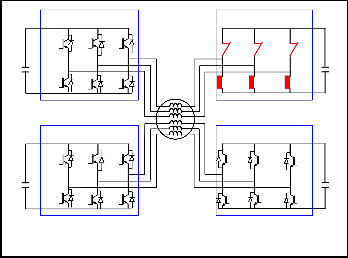
of the stator windings A.
Inverter A1 Inverter A2
[B] =
0
0
0 (13)
1
0
T11
T21 T31
T31
T21
T11
0
0
T’11 T’21 T’31
T’31
T’21
T’11
Inverter B1 Inverter B2
The simulation model is validated in the Matlab simulink environment. The dual open-end winding induction machine is fed by four PWM voltage source inverters based on V/f law.
T11
T21 T31
Dual open-end
T31
T21
T11
The following cycle of the operation, of t = 0 to t = 0.6 s, the
system has a starting cycle, from t = 0.6 s to t = 1s, the ma-
T’11 T’21 T’31
Winding IM
T’31
T’21
T’11
chine is working in no-load conditions. At time t = 1s, a load
torque Tr = 300mN is applied.
Figure 4 shows the pole voltage machine UA = (VsA11 -VsA12 )
- (VsA21 -VsA22 ), the pole voltage machine UB = (VsB11 -VsB12 ) -
(VsB21 -VsB22 ), the stator currents, the speed and the torque.
Fig 5. Feeding Dual open-end winding IM by four inverters then failed inverter A2
To avoid an imbalance between the two operating stator windings, one solution is to reduce the DC bus of the wind- ings B. The speed will be reduced to 70% of its nominal value for a load torqueTr = kn².
Figure 6 shows the simulation results for a load torque
Tr = kn². At t = 1.2 s we reconfigured the ordering of the in- verter A2 following a default.
SER ©
Fig 4. Pole voltage, stator currents, speed and torque for a ma- chine starting between 0 and 0.6s, then the nominal torque im- pact at t = 1 s
Fig 6. Stator currents, speed and torque for the failure of inverter A2 with speed limited at 70%
International Journal of Scientific & Engineering Research, Volume 4, Issue 7, July-2013 643
ISSN 2229-5518
Figure 9 shows the stator currents, the speed and the torque with the DC bus of the A1 inverter is double, when the A2 inverter is failed at t = 1.2s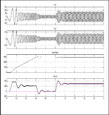
Figure 7 shows the evolution of the phase to phase volage inverters (VsA11 -VsA12 ) of entry A1, (VsA21 -VsA22 ) of entry A2 that equal to zero of failed inverter A2, (VsB11 -VsB12 ) of entry B1 and (VsB21 -VsB22 ) of entry B2. Thus machine voltage UA = (VsA11 -VsA12 ) - (VsA21 -VsA22 ) of winding A and UB = (VsB11 - VsB12 ) - (VsB21 -VsB22 ) of winding B.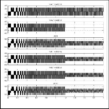
Fig 9. Stator currents, speed and torque for the failure A2 inverter with nominale speed and DC bus of the A1 inverter is double
Fig 7. Simulated waveforms of the phase to phase voltage inverters and machine for the failure inverter A2 at t = 1.2s
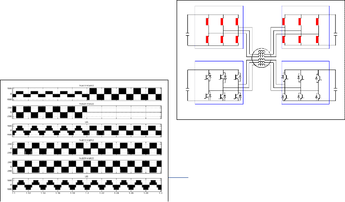
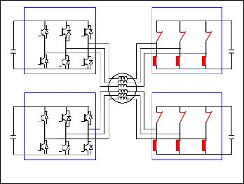
If we considered that the failure inverter A2, then it ensures the star of the winding A and the second failure occurred at the inverter A1 as shown by figure 10.
Also, it is possibole to operate the machine at nominal speed after the failure A2 inverter, however the inverters must
Inverter A1 Inverter A2
be dimensioned by the half power of the machine, and the DC
bus of the inverter A1 must be double. This solution although
T11
T21 T31
T31
T21
T11
it is very effective, it is difficult to achieve. Thereafter the first solution is considered.
Figure 8 shows the pole voltage of the A1 inverter after the
T’11 T’21 T’31
T’31
T’21
T’11
failed A2 inverter, we note at moment the level decrease of the pole voltage machine UA.
Inverter B1 Inverter B2
T
T11
21 T31
T31
T21
T11
T’11 T’21 T’31
Dual open-end
Winding IM
T’31
T’21
T’11
Fig 10.Feeding the machine for the failure of inverters A1 then A2
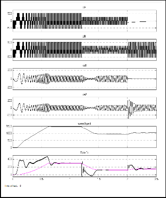
We have an equivalent operation to the open-end winding in- duction machine is supplied by two 2-level inverters, compulsori- ly speed reduced to 70% of nominal value for the load torque Tr = kn², as shown by the figure 11.
Fig 8. Enlarging effect of the phase to phase voltage inverters and
International Journal of Scientific & Engineering Research, Volume 4, Issue 7, July-2013 644
ISSN 2229-5518
Fig 11. Pole voltage of the machine, stator currents, speed and torque for the failure of inverters A1 then A2
If we considered that the failure inverter A2 and the second fail- ure occurred at the inverter B2 or inversely, similary for inverters A1 and B1; as shown by the figure 12.
Inverter A1 Inverter A2
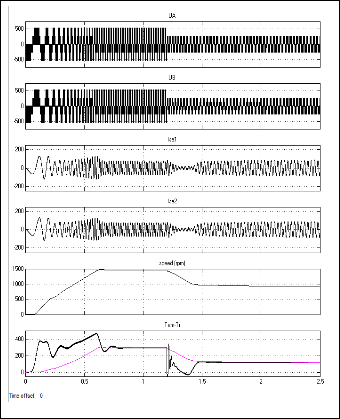
Fig 13. Pole voltage of the machine, stator currents, speed and torque
In the second case we considered third failed inverter. We considered primarily, first configuration of the second failure Figure 10. That is to say when one winding is supplied by the
T11
T21 T31
T31
T21
T11
two inverters B1 and B2.
The third failure will be at the inverter B1 or B2 as shown
T’11 T’
21 T’31
T’31
T’21
T’11
in Figure 14, This will ensure the star of the winding B.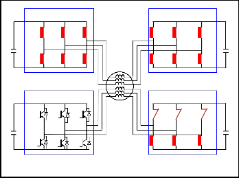
Similarly if the winding A is fed, the third failure will be at the inverter A1 or A2.
Inverter B1 Inverter B2
Inverter A1 Inverter A2
T11
T21 T31
T31
T21
T11
T11
T21 T31
T31
T21
T11
T’11 T’21 T’31
Dual Open-end
Winding IM
T’31
T’21
T’11
T’11 T’21 T’31
T’31
T’21
T’11
Fig 12.Feeding the machine for the failure of inverters A2 then B2
Then, we have an equivalent operation to the double star
Inverter B1 Inverter B2
asynchronous machine is fed by two three phase 2-level inverters, which must be reduced to 70% of nominal value for the load torque Tr = kn². The two failure inverters A2 and B2 must ensure
T11
T21 T31
T31
T21
T11
the star of the two windings A and B.
The simulation results of the evolution phase to phase-
T’11 T’21 T’31
Dual open-end
Winding IM
T’31
T’21
T’11
machine voltage, stator currents, speed and the torqueis shown by the figure 13.
Fig 14. Feeding the machine for the failure of inverters A2, B2 then A1
IJSER © 2013 http://www.ijser.org
International Journal of Scientific & Engineering Research, Volume 4, Issue 7, July-2013 645
ISSN 2229-5518
We will have an equivalent to the conventional induction machine with speed reduced to 50% of its nominal value operation.
Figure 15 shows the machine operation with the first fail- ure inverter A2 at t = 1.2s, the second failure inverter A1 at t =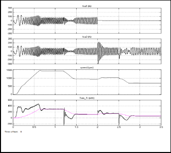
2s, and third failure inverter B2 at t = 2.5s.
Fig 15. The stator currents, speed and torque for the failure of invert- ers A2, A1 then B2
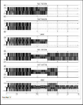
Figure 16 shows simulation results of the evolution voltage for the different failed inverters.
The phase to phase volage inverters (VsA21 - VsA22 ) of entry A2 that equal zero at t = 1.2 s, (VsA11 - VsA12 ) of entry A1 equal zero at t = 2 s , (VsB11 - VsB12 ) of entry B1 and (VsB21 - VsB22 ) of entry B2 equal zero at t = 2.5 s. Thus machine voltage UA = (VsA11 -VsA12 ) - (VsA21 -VsA22 ) of winding A and UB = (VsB11 - VsB12 ) - (VsB21 -VsB22 ) of winding B.
In the second case we considered the configuration of the second failure Figure 12. That is to say when the two windings are supplied by the two inverters A1 and B1.
Third failure will be at the inverter A1 or B1 feeding one of the two windings.
In this case you must open the ends of the winding, the two converters are down, the third inverter B2 will continue to ensure the star of the winding operation such a configuration is shown in Figure 14.
We will have an equivalent to the conventional induction machine with speed reduced to 50% of its nominal value operation.
Figure 17 shows the machine operation with the first failure inverter A2 at t = 1.2s, the second failure inverter B2 at t = 2s, and third failure inverter B1 at t = 2.5s.
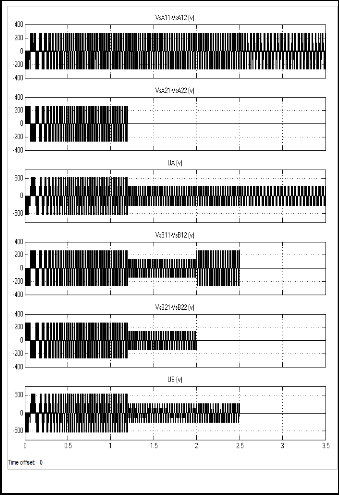
Figure 18 shows the evolution voltage for the different suc- cessive failed inverters.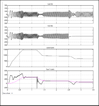
The phase to phase volage inverters (VsA11 -VsA12 ) of entry A1, (VsA21 -VsA22 ) of entry A2 that equal to zero of failed invert- er A2, (VsB11 -VsB12 ) of entry B1 and (VsB21 -VsB22 ) of entry B2that equal to zero of failed inverter B2 at t = 2s. Thus machine volt- age UA = (VsA11 -VsA12 ) - (VsA21 -VsA22 ) of winding A and UB = (VsB11 -VsB12 ) - (VsB21 -VsB22 ) of winding B,that equal to zero of failed inverters B1 and B2.
Fig 16. Simulated waveforms of the phase to phase voltage inverters and machine for the failed inverters A2, A1 then B2
Fig 17. The stator currents, speed and torque for the failed inverters
A2, B2 then B1
IJSER © 2013 http://www.ijser.org
International Journal of Scientific & Engineering Research, Volume 4, Issue 7, July-2013 646
ISSN 2229-5518
The simulation results show that It would be very interest-
ing to use the field oriented control strategy to reduce the currents peaks when the failures inverters.
Fig 18. Simulated waveforms of the phase to phase voltage inverters and machine for the failed inverters A2, B2 then B1.
The characteristics of the machine used: Power nominal P = 45 KW.
Speed n = 1450 tr/min. Resistance of stator Rs = 0.3 Ω. Resistance of rotor Rr = 0.046 Ω. Inductance of stator Ls = 17.9 mH. Inductance of rotor Lr = 18.6 mH. Mutual inductance Msr = 17.2 mH.
We implemented the simulation model of the dual open-end stator winding induction machine for voltage supply in the Matlabsimulink environment.
We have presented the operation of dual open-end stator winding is supplied by four three phase 2-level inverters in degraded mode; different successive failed inverters for feed- ing machine are studied.
The advantage of the machine in degraded mode is that it can continue to operate when a default appears in one, two or three of the four inverters.
This study shows the importance that presents such a ma- chine structure, for power segmentation, improved reliability and continuity of service of the system.
[1] F. Ben Ammar, S Guizani, “The improvement availability of a double star asynchronous machine supplied by redundant voltage source inverter,” Journal of electrical system JES Vol.4 issue 4 december 2008.
[2] M.Blanke, T. Sandberg, “Electrical Steering of vehicles–fault-tolerant analysis and design,” Microelectronics Reliability Elsevier pp 1421-
1432. 2006.
[3] S. Mantero, E.De Paola, G. Marina , “An optimized control strategy for double star motors configuration in redundancy operation mode,” EPE 99, Lausanne. (Conference proceedings)
[4] G.K Singh, V.Pant, Y.P Singh, “Voltage source inverter driven multi- phase induction machine, ” Journal of computer and Electrical Engi- neering Elsevier 29 pp 813-834, 2003.
[5] S. Guizani, F. Ben Ammar,“The eigenvalues analysis of the double star
induction machine supplied by redundant voltage source inverter,” Inter- national Review of Electrical Engineering I.R.E.E, Vol.3. N°.2, March-April 2008. (Personal communication)
[6] N.Moubayed, F. Meibody-Tabar , B. Davat, Rasoanarivo I, “Condi- tions of safely supplying of DSIM by two PWM-VSI” , EPE 99, Lau- sanne. (Conference proceedings)
[7] D.Hadiouche, H.Razik, A. Rezzoug, “Modelling of a double-star induc- tion motor with an arbitrary shift angle between its three phase winding, “
9th international conference on EPE, PEMC 2000 Kosice, Slovak Re-
public. (Conference proceedings)
[8] B. V. Reddy, V.T. Somasekhar,“A four-level inverter with open-end winding induction motor drive with a decoupled space vector PWM scheme”, National Power Electronics Conference – 2010. (Conference proceedings)
[9] G. Sambasiva, R.Siva , K.S. Chamdra, “A Twelve-Level Inverter System
for Dual- Fed Induction Motor Drive,” International journal of ad- vanced engineering sciences and technologies, IJAEST Vol No. 6, Issue N°. 2, 157 – 167, 2011.
[10] M.R Baiju, K. Gopakumar, K. Mohapatra, V.T Somasekhar, L.Umanand , “Five-level inverter voltage-space phasor generation for an open-end winding induction motor drive,”IEE Proc.-Electr. Power Appl., Vol. 150, No. 5, September 2003.
[11] V.T. Somasekhar, K. Gopakumar, P. Andre, V. Ranganathan,”A Novel PWM Inverter Switching Strategy for a Dual Two-level Inverter Fed Open-end Winding Induction Motor Drive,” IEEE PEDS 2001- Indone- sia. (Conference proceedings)
[12] A. Nayli, S. Guizani, F. Ben Ammar,”Open-end winding induction machine supplied by two flying capacitor multilevel inverters,” ICEESA
2013 Hammamet, Tunisia. (Conference proceedings)
[13] N.Rosaiah, C.HariKrishna, G.Satheesh, B. Reddy, “Decoupled space
vector PWM for dual inverter inverter fed open-end winding induction motor drive,” International journal of scientifs and engineering re- seach, Volume 3, Issue 10, October 2012.
[14] G. Gabriele, T. Angel, S.Padmanaban, O.Darko. “Multi-phase multi- level AC motor drive based on four three-phase two-level inverters”, Inter- national Symposium on Power Electronics, Electrical Drives, Auto- mation and Motion, SPEEDAM 2010. (Conference proceedings).
IJSER © 2013 http://www.ijser.org