International Journal of Scientific & Engineering Research, Volume 5, Issue 1, January-2014 202
ISSN 2229-5518
nguyensiphuoc@outlook.com
Abstract— Two matrix equations, Pascal matrix equation and inverse Pascal matrix, are derived and demonstrated in this work. These matrix equations are used for making a conversion and inversion between the coefficients of an analog low pass filter transfer function H(s) and a digital transfer function H(z). The involving of the Pascal’s triangle in both matrix equations is helpful, easier to transform between analog filter and digital filter and therefore, the procedure of design a digital filter form another digital filter is presented in this paper.
Index Terms— Bilinear z-transform, Pascal’s triangle, low pass to low pass, low pass to high pass, low pass to band pass, low pass to band stop, digital to digital filter, Pascal matrix equation, pre-warping frequency.
—————————— ——————————
=f
here are the procedures of design a digital filter (low pass, high pass, band pass and band stop), one of them is starting
c = cot(π f )
![]()
= f
U =
⇒
![]()
=
c
![]()
1 − ct
t
(1)
from a given analog low pass filter, transform it to analog
t tan(π L )
fs
L
1 − ct
filter which the same class of the desired digital filter using fre- quency transformations and then apply the bilinear z-transform
This matrix [T] is used to derive the Pascal matrix equation in the next sections.
with pre-warping frequencyI[2]. ThJis method wSith the involv- ER
ing the Pascal’s triangle derived the matrix equations, called
“Pascal matrix equation” and “Inverse Pascal matrix equation”,
they are used to find the relationship between the coefficients of
the transfer functions in s-domain and z-domain.
This paper introduces the procedure of designing a digital filter from a given digital filter by using Pascal matrix equation and inverse Pascal matrix equation.

A great application of the Pascal’s triangle is for finding the coefficients and expansion of a binomial expression (U+L)n. The table.1 below, illustrates a converting an analog low pass filter to a low pass, high pass, band pass and band stop digital filter. . Let insert zeros into Pascal’s triangle to make a matrix [T] having a size of (n+1;N+1) as shown in figure.1 below
Where n is the nth-order of the analog low pass filter and N is the Nth-order of the digital filter.
If the cut off frequency of the low pass and the upper cut off frequency of the band pass, band stop filter is fU. The cut off frequency of the high pass and the lower cut off frequency of
A digital filter (low pass, high pass, band pass and band stop) of the transfer function H(z) can be obtained from the transfer function H(s) of an designed analog low pass filter as the block diagram in fig.2 shows below
The table.1 illustrates more details for converting an analog low pass filter to a low pass, high pass, band pass and band stop digital filter.
From table.1, the relationship between the coefficients [Ai ], [Bi ] of the transfer function H(s) and [ai ], [bi ] can be expressed as the matrix equation below
[a] = [ P ][∆( A,U , L)]
the band pass, band stop filter is fL . The sampling frequency is fs , then
[b] = [ P ][∆(B,U , L)]
(6)
IJSER © 2014 http://www.ijser.org
International Journal of Scientific & Engineering Research, Volume 5, Issue 1, January-2014 203
ISSN 2229-5518
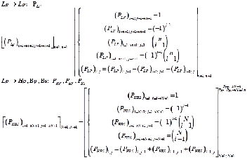
The matrix [P] contains the positive and negative binomial coefficients of the Pascal’s triangle in the first, last row and the first, last column corresponding to the edge size and the nth row of the Pascal’s triangle and another elements in the matrix [P] can be calculated from its left, diagonal and above ele- ments. It has a size of (N+1, N+1). There are two different ma- trices respectively for low pass filter PLP and PHBS for PHP (high pass), PBP (band pass), PBS (band stop) and they can be found as:
For low pass to band pass and low pass to band stop, the ma- trix [T] is used.
The subscripts of the coefficients [A] and [B] in the transfer function H(s) low pass filter is writing in ascending order for low pass, high pass, band pass and in descending order for band stop.
Base on the equation (6) and equation (7), one new formula can derived and it is called “The Pascal Matrix Equation” as is described in equation (8):
( ai −1 )
= ( P )
( A) (Ti; j )
i =1→ N +1; j =1 N +1;1
i =1→ N +1; j =1→ N +1 N +1; N +1
i =1; j =1→ N +1 1; n+1
i =1→n+1; j =1→ N +1 n+1; N +1
N +1;1
(8)
( bi −1 )
= ( P )
( B)
(Ti; j )
i =1→ N +1; j =1 N +1;1
i =1→ N +1; j =1→ N +1 N +1; N +1
i =1; j =1→ N +1 1; n+1
i =1→n+1; j =1→ N +1 n+1; N +1
N +1;1
The Pascal matrix equation is a general formula to transform the coefficients of an analog filter transfer function H(s) to the coefficients of a digital filter transfer function H(z).
The procedure of converting an analog low pass filter to a dig- ital filter were studied. The next sections will introduce how to invert a digital filter to an analog low pass filter using the Pas- cal matrix equation.
IJSER
The matrix [Δ] in equation (6) has a size of (N+1, 1) and it can
be found by multiplication between the coefficients matrix of
the analog low pass filter and the matrix T of the Pascal’s tri-
angle with zeros as shown in the equation (7).
The inverting a digital low pass, high pass, band pass and band stop to an analog filter is a method to transform the coef- ficients [ai] and [bi] of the transfer function H(z) to the coeffi-
∆
(A, U, L)
= A
T
(
j −1
i =1; j =1→ N =1 1; N +1
(
i =1; j =1→ n+1 1; n+1 i =1→n+1; j =1→ N +1
n+1; N +1
(7)
cients [Ai] and [Bi] of the transfer function H(s). This method
(
i =1; j =1→ N =1
( Bj −1 )i =1; j =1→ n+1
(Ti ; j )i =1→n+1; j =1→ N +1
can be done by using the Pascal matrix equation (8), the matrix
∆
=
1; N +1 1; n+1
n+1; N +1
[Ai] and [Bi] can be found as:
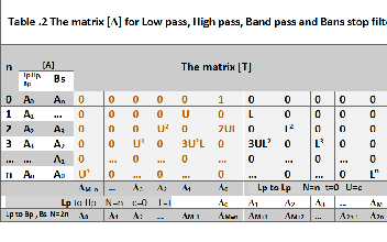
The table 2 below illustrated the matrix [Δ] for low pass, high
pass, band pass and band stop filter.
[ A]
= ([ P ] −1
[a]
) [T ] −1
1; n+1
N +1;N +1
N +1;1 1; n+1
n+1; n+1
[ B]
= ([ P ] −1
[b]
) [T ] −1
(9)

1; n+1
N +1;N +1
N +1;1 1; n+1
n+1; n+1
The equation (9) is called “the Inverse Pascal Matrix Equation” and it can be used to find the coefficients of the analog low pass filter from a digital filter.
In this equation, the involving of the inverse matrix [P]-1 and [T]-1 will not make easy computing and hand-calculation for lager matrix size. To overcome this problem, consider some features of the matrix [P] and [T] in the next section.
From table.2, for low pass filter, let t=0, then L=0, U=c, the matrix [T] becomes a matrix [T c ] has a size of (n+1; n+1) and the same for high pass filter, c=0, U=0, L=t, the matrix [T] is
There are some features of the matrix [P] and they can be used to find the inverse matrix [P]-1. For the matrix low pass [PLP ], if multiply the matrix by itself will give a diagonal matrix with all the numbers in the diagonal are equal to 2n [3], and from this the inverse matrix [PLP ] can be found as:
the matrix [T t ] as shown
( P )
( P )
= 2n [ I ]

LP i =1→n+1; j =1→n+1 n+1;n+1
LP i =1→n+1; j =1→n+1 n+1;n+1
∴ ( P )
−1 = =1 ( P )
(10)
LP i =1→n+1; j =1→n+1 n+1;n+1
2n
LP i =1→n+1; j =1→n+1
The inverse of the matrix [PHBS ] can be found similar way and
IJSER © 2014 http://www.ijser.org
International Journal of Scientific & Engineering Research, Volume 5, Issue 1, January-2014 204
ISSN 2229-5518
can be written as
. Inverse a digital band stop filter to an analog low pass filter
−1
P
= =1 (−1)i + j P
PHP → N=n
PBP , PBS → N =2 n (11)
( HBS )i =1→ N +1; j =1→ N +1
2n (
HBS i ; j )
i =1→ N +1; j =1→ N +1 N +1;N +1
[ A ]
= 1 (( −1)
i + j P
[a]
) [T ]
n 1 i 1; n+1
![]()
2N
HBS i ; j N +1; N +1
N +1;1
1; n+1
h inv n+1; n+1
+ − −
=
(18)
The matrix [T c ] and [T t ] are the diagonal matrix, so the inverse
[ B 1
=
1; 1
(( −1)
i + j P
i ; j
[b]
1; 1
1;1 ) [T
1; 1
+ − −
n i n+ 2N
HBS
N + N +
N +
1; n+1
h inv n+ n+
of them can be obtained by replacements each element in di-
agonal with its reciprocal as illustrated below
i −1 i −1
The methods covert and invert between the coefficients of an
analog low pass filter and a digital filter were studied. The
Pascal matrix equation and inverse matrix equation are de-
[T ] = [T ] −1
![]()
= 1
[T ][T ] −1
![]()
= 1
(12)
rived and they are easy to use for hand-calculation and com-
c − inv c n+1; n+1
T
t − inv t n+1; n+1
T
c i = j n+1;n+1
t i = j n+1;n+1
puting. One application of them is transformation a digital to
Let a matrix [T h ] has a size of (n+1; n+1) and it can be written like a left-half of the Pascal’s triangle with zeros [T] figure.1 as shown below:
The inverting of the matrix [T h ] is an upper-left triangular ma- trix [T h-inv ] of the size (n+1; n+1) and it can be found as follow- ing steps:
- If the main anti-diagonal is the first, then all the odd anti- diagonal above it are 3rd, 5th, 7th… and corresponding to
m=1,2,3,4,…
another digital filter.
This section introduces a new method to design a digital from another filter. Given a digital filter, invert it to an analog low pass filter using inverse Pascal matrix equation and from ana- log low pass filter converts it to a desired digital filter using Pascal matrix equation. A block diagram in figure.3 illustrates the transformation from a digital to another digital filter.
- Each element in the mth anti-diagonal can be expressed in the formula as:
(T )
= K L
m −1
U − j +1
(13)
Given the coefficients [ag ] and [bg ] of a digital filter, invert
h− inv ( n+1− 2( m−1)− j +1) ; j )
![]()
( n+1− 2( m−1)− j +1) ; j )
U
them to the coefficients [Ag ] and [Bg ] of an analog low pass
-The coefficients K can be calculated as below:
filter. The equation (9) is rewritten as
. All the K in main anti-diagonal are equal to 1.
A
= ( P −1
a
−1
T
. From m= 2, 3, 4, 5… all the K in the first column are
g 1; n+1
g N +1;N +1 g N +1;1 g n+1; n+1
(19)
replaced with -2, +2,-2, +2… accordingly.
B
−1
= P
b
−1
T
1; n+1
g N +1;N +1
g N +1;1 1; n+1
g n+1; n+1
. All another K in all anti-diagonals can be found by
K( n+1−2( m−1)− j+1; j ) = K( n+1−2( m−1)− j+2; j ) − K( n+1−2( m−1)− j +3;j ) (14)
Then convert [Ag ] and [Bg ] to the coefficients [ad ] and [b d ] of a desired digital filter. The equation (8) is rewritten as
-All another elements in the matrix [T h-inv ] equal to zero.
[ d ] N +1;1
N +1; N +1
g 1; n+1 [ d ] n+1; N +1 )
a = P
A T
+ (20)
[bd ] = [ Pd ] ( Bg 1; n+1 [Td ] )
N +1;1
The matrix [T h-inv ] can be used to inverse form a digital band
pass and band stop to an analog low pass filter.
From the equation (9), (10), (11), (12) and the matrix [Th-inv ],
From equation (19) and (20), a new equation, called transform-
ing Pascal matrix equation, is found, this equation is used for
transform a digital to another digital filter.
the inverse Pascal matrix equation for low to low pass, high
[a ]
= [ P ]
((( P −1 a
−1
) T )
[T ] )
d N +1;1
d N +1;N +1
g N +1;N +1 g N +1;1 g n+1;n+1 1;n+1
d n+1;N +1
n+1;1
(21)
pass to low pass, band pass to low pass and band stop can be
[b ]
= [ P ]
((( P −1
b
−1
) T )
[T ] )
d N +1;1
d N +1;N +1
g N +1;N +1
g N +1;1
g n+1;n+1 1;n+1
d n+1;N +1
n+1;1
expressed as
. Inverse a digital low pass filter to an analog low pass filter
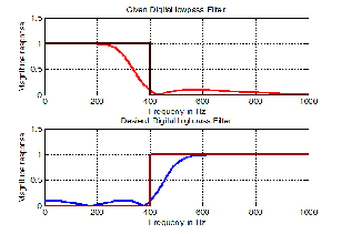
Example 1: Convert a digital 4th-order Chevbyshev type 2 low
pass filter HLP (z) at cut off frequency at 400Hz, 20dB stop band ripple to a digital high pass filter at sampling frequency
[ A]
= 1 ([ P
] [a]
) [T ]
2 kHz.![]()
1; n+1 n
1
LP n+1; n+1
n+1;1 1; n+1
c − inv n+1; n+1
(15)
[ B] =
1; n+1
![]()
n ([ PLP ] n+1; n+1 [b]n+1;1 ) [Tc − inv ]n+1; n+1
H ( z ) =
![]()
2.6744+ 1.7645z−1 + 3.9222z−2 + 1.7645z−3 + 2.6744z−4
LP −1
−2 −3 −4
. Inverse a digital high pass filter to an analog low pass filter
17.6412 -18.2293z + 16.3414;z -4.0816z + 1.1282z
=1
From equation (21), the conversion of the digital low pass fil-
[ A]1; n+1
= 2n (( −1)
i + j
i ; j n+1; n+1 n+1;1 n+1; n+1
ter to a digital high pass is expressed as
−
n+
B =
1; n 1
1 ( −1)
1; 1
i ; j n 1; n 1 n 1;1 n 1; n 1
(16)
![]()
+ 2
i + j
+ + +
− + +
1; n+1
. Inverse a digital band pass filter to an analog low pass filter
5;1
![]()
4 [ HBS ]5;5 (
5;5
1;5 [ c − inv ] 1;5 [ t ] )
a = 1 P
(( P
a ) T ) T
[ ]1; n+1
![]()
N (
HBS i ; j N +1; N +1 [ ]N +1;1 ) [ h− inv ]n+1; n+1
b =
5;1
2
![]()
4 [ PHBS ]5;5 ((([ PLP ]5;5 bg
5;1 5;1
)1;5 [Tc inv ] )1;5 [Tt ] )
A = 1
2
( −1)i + j P
a T
1; n+1
1
2 5;1 − 5;1
=
(17)
B
1; n+1
N (( 1)
i ; j N +1; N +1 N +1;1 n+1; n+1
= −
i + j
−
![]()
![]()
2
1; +1
400 400
n = = π = = π =
n 4;c
cot( ) 1.3764; t
tan( ) 0.7265
IJSER © 2014 http://www.ijser.org
2000 2000
ag = [2.6744; 1.7645; 3.9222; 1.7645; 2.6744]
bg = [17.6412; -18.2293; 16.3414; -4.0816; 1.1282]
International Journal of Scientific & Engineering Research, Volume 5, Issue 1, January-2014 205
ISSN 2229-5518
From equation (21), the conversion of the digital band pass filter to a digital band stop is expressed as
[ d ]5;1
4 [ HBS ]5;5 (
BP 5;5 g 5;1 1;3 [ h− inv ]3;3 1;3 [ t ]3;5 )
![]()
a = 1 P
b = 1 P
(( ( −1)i + j P
(( ( −1)i + j P
a ) T
b ) T
) T
5;1
) T
![]()
[ d ]
5;1
4 [ HBS ]5;5 (
BP 5;5 g 5;1 1;3 [ c − inv ]3;3 1;3 [ t ]3;5 )
5;1
1 1 1 1 1 2.6744
4 2 0 -2 -4 1.7645
12.8
0
![]()
![]()
n = 4;c = cot(π 1000 ) = 0.3249 ; t = tan(π 4000 ) = 0.3249
10000 10000
([ PLP ] ag ) = 6 0 -2 0 6 3.9222 = 24.2484
4 -2 0 2 -4 1.7645 0
ag = [0.2528 0 -0.2944 0 0.2528]
1 -1 1 -1 1 2.6744 5.7420
b = 1.1638 0 0.6557 0 0.2919
1 1 1 1 1 17.6412
12.8
g [ ]
4 2 0 -2 -4 -18.2293
37.7566
([ PLP ] bg ) = 6 0 -2 0 6 16.3414 = 79.9336
1 1 1 1 1 1 -1 1 -1 1 0.2528
0.2056
4 -2 0 2 -4 -4.0816
94.3474
=1 -4 -2 0 2 4 4 -2 0 2 -4 0
-2 0 7.5777 0 0 1 0 0
0
1 -1 1 -1 1 1.1282
57.4217
[ad ]5;1 = 4 6 0 -2 0 6 6 0 -2 0 6 -0.2944 0 2.7528 0
0 0.3633 0 0.3633 0
= 0.0111
-4 2 0 -2 4 4 2 0 -2 -4 0
1 0 0
0.1320 0 0.2639 0 0.1320 0
1 0 0 0 0
0 0.7265 0 0 0
1 -1 1 -1 1 1 1 1 1 1 0.2528
1;3
5;1
0.2056
1.5415
([PLP ]ag ) [Tc−inv ] = [12.8 0 24.2484 0 5.7420]0 0 0.5279 0 0
1 1 1 1 1 1 -1 1 -1 1
1.1638
1;5
0 0 0 0.3835 0
=1 -4 -2 0 2 4 4 -2
0 2 -4 0
-2 0 7.5777 0 0 1 0 0
0
0 0 0 0 0.2786
[bd ] = 6 0 -2 0 6 6 0 -2 0 6 0.6557 0 2.7528 0
2
0 0.3633 0 0.3633 0
= -1.7888
-4 2 0 -2 4 4 2 0 -2 -4 0
1 0 0
0.1320 0 0.2639 0 0.1320 0
= [12.8 0 12.8 0 1.6]
1 -1 1 -1 1 1 1 1 1 1 0.2919
0.6696
1 0 0 0 0
1;3
5;1
0 0.7265 0
0 0

([PLP ]bg ) [Tc−inv ] = [12.8 37.7566 79.9336 94.3474 57.4217]0 0 0.5279 0 0
1;5
0 0 0 0.3835 0
= [12.8 27.4318 42.1941 36.1837 16]
0 0 0 0 0.2786
1 0 0 0 0
0 0.7265 0 0 0
(([ PLP ] ag ) [Tc −inv ]) [Tt ]5;5 = [12.8 0 12.8 0 1.6] 0 0 0.5279 0 0
1;5 1;5
0 0 0 0.3835 0
0
0 0 0 0.2786
= [12.8 0 6.7566 0 0.4458]
1 0 0 0 0
0
0.7265 0 0 0
(([ PLP ] bg ) [Tc −inv ]) [Tt ]5;5 = [12.8 37.7566 79.9336 94.3474 57.4217] 0 0 0.5279 0 0
1;5 1;5
0 0 0 0.3835 0
0 0 0 0 0.2786
= [12.8 19.9304 22.2727 13.8770
4.4582]
1 1 1 1 1 12.8
1 -4 -2 0 2 4 0
1.2501
-3.0885
[ d ]
5;1
![]()
6 0 -2 0 6 6.7566
24 - -
a =
= 4.1226
4 2 0
2 4 0
-3.0885
1 -1 1 -1 1 0.4458
1.2501
1 1 1 1 1 12.8
4.5836
1 -4 -2 0 2 4 19.9304 -2.8421
[bd ]5;1
![]()
= 6 0 -2 0 6 22
24 - -
.2727 = 3.6877
4 2 0
2 4 13.8770 -1.3287
1 -1 1 -1 1 4.4582 0.3577
1.2501 -3.0885z−1 + 4.1226z−2 -3.0885z−3 + 1.2501z−4
![]()
∴ H HP ( z ) = 4.5836 -2.8421z−1 + 3.6877z−2 -1.3287z−3 + 0.3577z−4

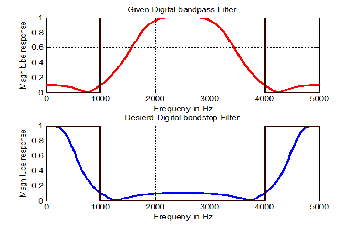
Example 2: Convert a digital 4th-order Chevbyshev type 2 band pass filter HBp (z) at lower cut off frequency at 1Hz, up- per cut off frequency 4kHz and 20dB stop band ripple to a digital band stop filter at sampling frequency 10kHz.
0.2528 -0.2944z−2 +0.2528z−4
The new method were studied for converse and inverse be- tween an analog low pass filter with the transfer function H(s) and a digital filter (low pass, high pass, band pass and band stop) with the transfer function H(z) and from that this meth- od can be applied to transform a given digital filter into an- other digital filter. The involving of the Pascal’s triangle uses in the Pascal matrix equation and inverse Pascal matrix equa- tion, as presented and demonstrated in the examples, made the work easier for hand-calculation and computing when transforming between s-domain and z-domain. The features of the matrix [P] and [T] are so helpful to find the inverse matrix which are not easy to do with the larger matrix size. The algo- rithm of this method converse and inverse is so simple due to all operations imply the matrix multiplication and so it is more effective to program and calculation.
[1] Emmanuel C. Ifeacor, Barrie W. Jervis. (1993). Digital Sig- nal Processing. Addison-Wesley, USA
[2] Konopacki J. (2005). The frequency Transformation by Ma- trix Operation and its Application in iir Filters Design. IEEE
H BP
( z ) =
![]()
1.1638 + 0.6557z−2 +0.2919z−4
Signal Processing Letters, Vol. 12, No.1, pp 5-8, January.
[3] F. J. Garcia-Ugalde. (2011). Z-transform by Pascal Matrix
IJSER © 2014 http://www.ijser.org
International Journal of Scientific & Engineering Research, Volume 5, Issue 1, January-2014
ISSN 2229-5518
206
and its Applications in the Design of IIR Filters. IEEE, vol.9, N0.3, pp.355-366, December.
[4] Chivapreecha, S. (2005). Bilinear s-z frequency transfor mation using matrix Pascal operation, IEEE, Communications and Information Technology, Vol.l, pp 764-767.
IJSER lb) 2014