International Journal of Scientific & Engineering Research, Volume 5, Issue 1, January-2014 775
ISSN 2229-5518
Survey and Simulation based Performance Analysis of TCP-Variants in terms of Throughput, Delay and drop Packets over MANETs
Prakash B. Khelage Dr. Uttam Kolekar
Asst. Professor Department of Information Technology Principal
UMIT, SNDT Women's University, Mumbai-400049, India Smt. Indira Gandhi College of Engineering, prakashkhelage@rediffmail.com, Navi Mumbai-400709, India. uttamkolekar@gmail.com
Abstract—Transmission Control Protocol (TCP) is a reliable which maintains end-to-end senentics and it is one of the core of the internet protocol (IP) suite responsible for transmission of internet traffic and very efficient for wired networks. However, experimental analysis and research showed that, TCP’s congeation control algorithm performs poorly over Mobile Ad-Hoc Networks with degraded throughputs, fairness services and energy consumption. In this paper we present the reviews and simulated result based comparision of TCP-Variants in terms of throughput, delay and packet drop. Our result based analysis showed that, traditional TCP congestion control protocol fails in MANET whereas Proactive and BW E based TCP-variants gives improved performance in terms of throughput, delay and packet drop. Hence there is motivation for RTT and BW E based investigation and research desirable for adapting TCP over Mobile Ad-Hoc Networks.
Index Terms— TCP, Congestion W indow, Congestion Control, Congestion Avidence, MANET, Bandwidth Estimate (BW E) , Round Trip
Time(RTT), Network simulator, throughput, delay, packet drop.
—————————— ——————————
1 INTRODUCTION
IJSER
HE MANET is considered as promising communication network in situations where rapid deployment and self- configuration are essential. In ad hoc networks, nodes are allowed to communicate with each other without any existing infrastructure [3]. Here every node should also play the role of a router. This kind of networking can be applied to scenarios like conference room, disaster management, and battle field communication and places where deployment of infrastruc-
ture is either difficult or costly.
The phenomenal growth experienced by the Internet over the
last decade has been supported by a wide variety of evolving
mechanisms to meet the requirements of emerging, demand-
ing applications. The basic TCP/IP protocol suite has been
instrumental in developing today’s Internet. In particular, TCP
has been successful due to its robustness in reacting dynami-
cally to changing network traffic conditions and providing
reliability on an end-to-end basis. This wide acceptance has
driven the development of many TCP applications, motivating
the extension of this protocol to wireless networks. These net-
works pose some critical challenges to TCP since it was not
originally designed to work in such complex environments, where the level of bit error rate (BER) is not negligible due to the physical medium. High mobility may further degrade the end-to-end performance because TCP reduces its transmission
rate whenever it perceives a dropped packet.
This paper focused on studuing the impact of mobile ad hoc
environment characteristics on the throughput, delay and
packet drop with eight major TCP variants (Tahoe, Reno, New
Reno, Westwood, WestwoodNR, Vegas, Sack, Fack) over basic
validation network model such as congestion, link failure,
signal loss and interference as well as chain and grid network
scenario.
The reminder of the paper is organized as follows: brif ex-
plation with digram about MANET characteristics in section 2, section 3 presents TCP congestion control algorithms along with congestion window trace diagrams, section 4 explains eight TCP variant with its Psudocode and problems, section 5 gives brif information about tools and technique used to gen- erate results, section 6 presents basic validation model , simu- lation screnario’s and obtained results, finally concluded with the opinion of possible future work.
2 MANET CHARACTERISTICS
The main MANET characteristics that can cause packet loss are: mobility [9] [10], wireless channel, and power constraints.
2.1 Mobility:-
All devices in MANET are free to move, so an on-going con- nection should be kept alive to support mobility. However, once the host moves the topology will change and this may lead to one of the following situations:
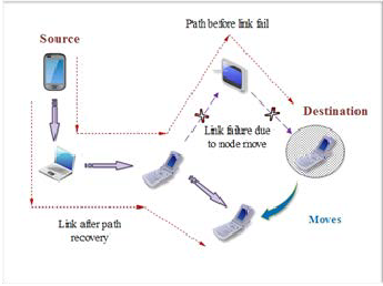
2.1.1 Route Failure
They are frequent events due to mobility in MANET. And it needs to re-establish a new transmission route to adjust to the topological changes. Once route failure occurs, it may accom- pany with a frequent of route change and failure, packet reor- dering in the sender and the receiver side, not to forget some packets will drop in the way.
2.1.2 Network Partition
A network partition occurs when a node in a MANET moves away from the network thereby causing an isolation of some part of the network by breaking it into two isolated parts. These isolated parts are called partitions.
IJSER © 2014 http://www.ijser.org
International Journal of Scientific & Engineering Research, Volume 5, Issue 1, January-2014 776
ISSN 2229-5518
2.2 Wireless Channel:-
Mobile nodes use wireless channel as a medium to send and receive data. However, it is well known that wireless channel is weak, unreliable and unprotected from outside signals. In other words, wireless channel prone the following complexi- ties:
2.2.1 High Bit Error Rate
The use of wireless channel is vulnerable to errors due to sig- nal attenuation, interference, obstacles and multipath fading. These errors may generate packet loss within a very short du- ration or receive corrupted packet at the receiver.
2.1.2 Contention
The use of shared wireless channel limits the ability of a node to send packets. Two types of contention:-
(i) Interflow contention which refers to the contention experi- enced by a node due to transmission by nearby flow.
(ii) Intraflow contention which refers to the contention within same node due to the forward data transmissions and reverses ACK transmission. Generally, contention may produce packet loss and delay.
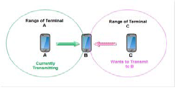
2.1.3 Hidden & Exposed Terminal
Fig. 1 Hidden and Exposed Station Problem
We show a typical scenario where the exposed terminal problem occurs. Let us assume that node A and C are within B’s transmis- sion range, and A is outside C’s transmission range. Let us also assume that B is transmitting to A, and C has a frame to be trans- mitted to D. According to the carrier sense mechanism, C senses a busy channel because of B’s transmission. Therefore, station C will refrain from transmitting to D, although this transmission would not cause interference at A. The exposed station problem may thus result in a reduction of channel utilization.
2.3 Power Constraints:-
Mobile node is generally a small device with a limited power supply and processing power. However, each node acts as a host and a router simultaneously because not all mobile nodes communicate directly with each other and this requires an additional energy. This imposes a route change or network partition when node energy is low.
3 TCP CONGESTION CONTROL ALGORITHM
The congestion control algorithms which are used in TCP pro- col such as slow start , congestion avoidance , fast retransmit
IJSER
A typical hidden terminal situation is depicted in Fig. 3. Sta-
tions A and C have a frame to transmit to station B. Station A
cannot detect C’s transmission because it is outside the trans-
mission range of C. Station C (resp. A) Is therefore “hidden” to
station A (resp. C). Since the transmission areas of A and C are
not disjoint, there will be packet collisions at B. These colli- sions make the transmission from A and C toward B.
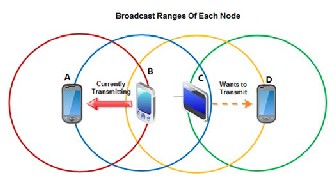
Hidden Station Problem
and fast recovery [1] [2] [12]are explained with congestion
Window trace diagram below.
3.1 Slow Start
Slow-start is one of the algorithms that TCP uses to control congestion inside the network. It is also known as the expo- nential growth phase. Slow start [2] is conducted in the begin- ning of every TCP connection and its main purpose is to find the maximum available bandwidth at which it can send data without ca using the network to be congested. The Slow-Start, improperly called like this, actually increases exponentially the size of the congestion window. The purpose of Slow-Start is to fill as soon as possible a transmission channel [3]. During the exponential growth phase, slow-start works by increasing the TCP congestion window each time the acknowledgment is received. It increases the window size by the number of seg- ments acknowledged. This happens until either an acknowl- edgment is not received for some segment or a predetermined threshold value is reached. If a loss event occurs, TCP assumes that it is due to network congestion and takes steps to reduce the offered load on the network. Once the threshold has been reached, TCP enters the linear growth (congestion avoidance) phase. At this point, the window is increased by 1 segment for each RTT. This happens until a loss event occurs [1].
Slow Start Algorithm:
Initial: CWND = 1;
For (each packet Acked)
Esposed Station Problem
CWND++;
IJSER © 2014 http://www.ijser.org
International Journal of Scientific & Engineering Research, Volume 5, Issue 1, January-2014 777
ISSN 2229-5518
Until (congestion event/ CWND>SSTreshHold)
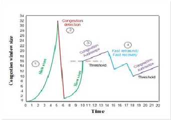
Fig. 2 TCP Congestion Window Trace
number of received duplicate acknowledgements and enters into the Fast Recovery phase [12].
3.2 Congestion Avoidence
If the receiver window is large enough, the slow start mecha- nism described in the previous routers in between the hosts will start discarding packets [2]. TCP interprets packet loss as
3.3 Fast Recovery
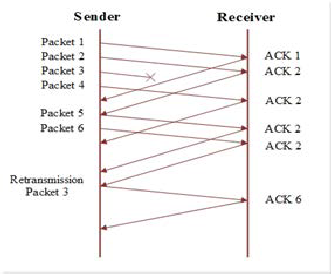
Fig. 3 Fast retransmit
IJSER
a sign of congestion, and when this happens TCP invokes the
Congestion Avoidance mechanism. This variable, SSTresh-
Hold, is the slow start threshold which TCP uses to determine
if slow start or congestion avoidance is to be conducted.
Congestion Avoidance Algorithm:
/* slow start is over and CWND>SSTreshHold */
every Ack:
CWND = CWND + (1/CWND) Until (Timeout or 3 DUPACKs)
3.3 Fast Retransmit
If an out-of-order segment is received TCP generates a so called duplicate acknowledgment. This duplicate acknowl- edgment is sent immediately from the receiver to the sender indicating that a segment arrived out-of-order, and which segment that was supposed to be received. Since it is not pos- sible to know whether the duplicate acknowledgment was caused by a lost segment or just reordering of segments, the sender waits for three duplicate acknowledgments before re- transmitting the segment. If this limit would have been lower, this would increase the chance of reordered segments causing duplicates to be created, and transmitted needlessly. The ad- vantage of this mechanism is that TCP does not have to wait for the retransmission timer to expire. It simply assumes that three duplicate acknowledgments is a good indicator of a lost segment [2].
If the congestion was indicated by duplicate acknowledge- ments, the TCP sender goes into the Fast Retransmit mode to retransmit what appears to be lost packet without waiting for the retransmission timer to expire. Then, the sender sets the SSTreshHold to half of the current congestion window and the new congestion window to the new SSTreshHold plus the
During Fast Recovery, the TCP New Reno distinguishes be-
tween a “partial” ACK and a “full” ACK. A full ACK
acknowledges all segments that were outstanding at the start of fast recovery, while a partial ACK acknowledges some but not all of this outstanding data. After fast retransmit is con- duct congestion avoidance and not slow start is performed.
This behavior is called Fast Recovery [2] [12]. Fast recovery is an algorithm allows for higher throughput under congestion, especially when using large congestion windows. Receiving three duplicate acknowledgments tells TCP more than the expiration of the retransmission timer. Since the receiving, TCP only can generate duplicate acknowledgments when it is receiving other segments it is an indication that data still flows between the different hosts, and that the congestion is not that severe. By using this approach, skipping the slow start, the TCP does not reduce the transfer rate unnecessarily much.
Fast Recovery Algorithm:
/* after fast retransmit; do not enter slow start */ SSTreshHold = CWND / 2;
CWND = SSTreshHold + 3; each DACK received; CWND ++;
Send new packet if allow; After receiving an Ack:
if partial Ack;
Stay in fast recovery;
Retransmit next lost packet (one packet per RTT);
if Full Ack;
CWND = SSTreshHold; Exit fast recovery;
Invoke Congestion Avoidance Algorithm; When Timeout:
SSTreshHold = CWND /2;
IJSER © 2014 http://www.ijser.org
International Journal of Scientific & Engineering Research, Volume 5, Issue 1, January-2014 778
ISSN 2229-5518
CWND = 1;
Invoke Slow Start Algorithm;
4 TCP VARIANTS
4.1 TCP Tahoe
Early TCP implementations followed a go-back- model using cumulative positive acknowledgment and requiring a re- transmit timer expiration to re-send data lost during transport [6] In the process of trying to improve the original TCP three traffic management mechanisms slow start, congestion avoid- ance and fast retransmit were introduced to the original TCP and the new TCP version was named as TCP Tahoe.TCP Ta- hoe is the TCP variant developed by Jacobson in 1988. It uses Additive Increase Multiplicative Decrease (AIMD) algorithm to adjust window size. It means that increases the congestion window by one for successful packet delivery and reduces the window to half of its actual size in case of data loss or any de- lay only when it receives the first negative acknowledge. In case of timeout event, it reduces congestion window to 1 MSS [7].
• TCP Tahoe uses packet loss probability to adjust the conges- tion window size.
• During Slow Start phase, TCP Tahoe increases window size
exponentially i.e. for every acknowledgement received, it
4.2 TCP Reno
TCP Reno retains the basic principle of Tahoe, such as slow starts and the coarse grain retransmit timer [12]. However it adds some intelligence over it so that lost packets are detected earlier and the pipeline is not emptied every time a packet is lost. Reno requires that we receive immediate acknowledge- ment whenever a segment is received. The logic behind this is that whenever we receive a duplicate acknowledgment, then his duplicate acknowledgment could have been received if the next segment in sequence expected, has been delayed in the network and the segments reached there out of order or else that the packet is lost. If we receive a number of duplicate acknowledgements then that means that sufficient time have passed and even if the segment had taken a longer path, it should have gotten to the receiver by now. There is a very high probability that it was lost. So Reno suggests Fast Re- Transmit. Whenever it receives 3 duplicate ACK‘s, take it as a sign that the segment was lost, so re-transmit the segment without waiting for timeout. Thus it manages to re-transmit the segment with the pipe almost full. Another modification that Reno makes is in that after a packet loss, it does not re- duce the congestion window to 1. Since this empties the pipe. It enters into an algorithm which is called Fast-Recovery.
sends two packets.
IJSEPsudocode for RReno:
• During Congestion Avoidance, it increases the window size
by one packet per Round Trip Time (RTT) so as to avoid con-
gestion.
• In case of packet loss, it reduces the window size to one and
enters in Slow Start phase.
Psudocode for Tahoe: Initially:
CWND = 1;
SSTreshHoldHold = AWS; /* when TCP begins for the first time*/
New ack received:
If (CWND < SSTreshHold)
/* Slow Start*/
CWND = CWND + 1; Else
/* Congestion Avoidance */ CWND = CWND + 1/CWND;
Timeout:
/* Multiplicative decrease */ SSTreshHold = CWND/2; CWND = 1;
Problems
Due to automatic set back to slow start mode of operation with initial congestion window of one every time packet loss is detected, TCP Tahoe does not prevent the communication link from going empty. Hence this may have high cost in high bandwidth product link.
Step 1: Initially
0<CWND<= min (4*mss, max (2*mss, 4380 bytes)) SSThreshholdHold = max (CWND/2, 2*MSS)
Step 2: Slow Start Algorithm (Exponential Increases)
if (receive acks && CWND SSThreshholdHold) CWND = CWND+1;
Step 3: Congestion Avoidance Algorithm (Additive increase)
if (receive ACKs) {
if (CWND > SSThreshholdHold)
CWND = CWND + ( segsize * segsize / CWND);
else
CWND = CWND + 1}
Step 4: Fast Retransmission
if (congestion) {
if (Receive same Acks 3 time or retransmission time out) {
SSThreshholdHold = CWND/2; Retransmit lossed packet
Problems:
Reno performs very well when the packet losses are small. But when we have multiple packet losses in one window then it doesn’t perform too well and its performance is almost the same as Tahoe under conditions of high packet loss. The rea- son is that it can only detect a single packet loss. If there is multiple packet drops then the first info about the packet loss comes when sender receive the duplicate ACK’s. But the in- formation about the second packet which was lost will come only after the ACK for the retransmitted first segment reaches the sender after one RTT. Another problem is that if the wid- ow is very small when the loss occurs then sender would nev-
IJSER © 2014 http://www.ijser.org
International Journal of Scientific & Engineering Research, Volume 5, Issue 1, January-2014 779
ISSN 2229-5518
er receive enough duplicate acknowledgements for a fast re- transmit and have to wait for a coarse grained timeout. Thus it cannot effectively detect multiple packet losses.
4.3 TCP New Reno
The experimental version of TCP Reno is known as TCP New Reno [8]. It is slightly different than TCP Reno in fast recovery algorithm. New Reno is more competent than Reno when multiple packets losses occur. New Reno and Reno both corre- spond to go through fast retransmit when multiple duplicate packets received, but it does not come out from fast recovery phase until all outstanding data was not acknowledged . It implies that in New Reno, partial ACK do not take TCP out of fast recovery but they are treated as an indicator that the packet in the sequence space has been lost, and should be re- transmitted. Therefore, when multiple packets are lost from a single window of data, at this time New Reno can improve without retransmission time out. The retransmitting rate is one packet loss per round trip time until all of the lost packets from that window have been transmitted. It exist in fast recov- ery till all the data is injected into network, and still waiting for an acknowledgement that fast recovery was initiated.
The critical issue in TCP New Reno [8] is that it is capable of handling multiple packet losses in a single window. It is
limited to detecting and resending only one packet loss per
CWND = SSThreshholdHold;
exit and call congestion avoidance step}}}
Problems:
Problem with New Reno is that the constraint of retransmit- ting at most one loss packet per RTT results in substantial de- lay in retransmitting the later dropped packets in the window. Thus the available bandwidth is not effectively utilized.
4.4 TCP Selective Acknowledgment (Sack)
The Selective Acknowledgment (SACK) mechanism is an ex- tension to Transmission Control Protocol’s (TCP) ACK mech- anism, allows a data receiver to explicitly acknowledge ar- rived out-of-order data to a data sender. When using SACKs, a TCP data sender need not retransmit SACKed data during the loss recovery period. Previous research showed that SACKs improve TCP throughput when multiple losses occur within the same window. The success of SACK-based loss recovery algorithm is proportional to the SACK information received from the data receiver [9].
With selective acknowledgments, the data receiver can in- form the sender about all segments that have arrived success- fully, so the sender need retransmit only the segments that have actually been lost [6]. TCP with ‘Selective Acknowledg- ments’ is an extension of TCP Reno and it works around the
problems face by TCP Reno and TCP New-Reno, namely de-
IJSER
round -trip-time. This insufficiency becomes more distinct as
the delay-bandwidth becomes greater.
However, still there are situations when stalls can occur if
packets are lost in successive windows, like all of the previous
versions of TCP New Reno which infer that all lost packets are due to congestion and it may therefore unnecessarily cut the congestion window size when errors occur.There are [5] some steps of congestion control for New Reno transmission control
protocol.
Psudocode for New Reno: Step 1: Initially
0<CWND<= min (4*mss, max (2*mss, 4380 bytes))
SSThreshholdHold = max (CWND/2, 2*MSS) Step 2: Slow Start Algorithm (Exponential Increases) if (receive acks && CWND SSThreshholdHold)
CWND = CWND+1;
Step 3: Congestion Avoidance Algorithm (Additive increase)
if (receive ACKs) {
if (CWND > SSThreshholdHold)
CWND = CWND + (seg_size * seg_size / CWND);
else
CWND = CWND + 1}
Step 4: Congestion Detection Algorithm (Multiplicative De-
crease): Fast Retransmission and Fast Recovery
if (congestion) {
if (Receive same Acks 3 time or retransmission time out) { SSThreshholdHold = CWND/2;
if (Retransmission time out) {
CWND = initial;
exit and call Slow Start step;
else /* Receive same Acks 3 time*/
tection of multiple lost packets, and re-transmission of more
than one lost packet per RTT. SACK retains the Slow-Start
and Fast Re-Transmit parts of Reno. It also has the coarse
grained timeout of Tahoe to fall back on, in case a packet loss
is not detected by the modified algorithm. TCP-Sack requires
that segments not be acknowledged cumulatively but should
be acknowledged selectively. Thus each ACK has a block which describes which segments are being acknowledged. Thus the sender has a picture of which segments have been acknowledged and which are still outstanding. Whenever the
sender enters fast recovery, it initializes a variable pipe which is an estimate of how much data is outstanding in the net- work, and it also set CWND to half the current size. Every time it receives an ACK it reduces the pipe by 1 and every time it retransmits a segment it increments it by 1. Whenever the pipe goes smaller than the CWD window it checks which segments are not received and send them. If there are no such segments outstanding then it sends a new packet. Thus more than one lost segment can be sent in one RTT.
Problems:
The biggest problem with SACK is that currently selective acknowledgements are not provided by the receiver to im- plement SACK we’ll need to implement selective acknowl- edgment which is not a very easy task and Requires modifica- tion to the acknowledgement procedures at both sender and receiver sides. Energy consumption is higher then new reno due to additional overheads.
4.5 TCP Westwood
TCP Westwood proposes an end-to-end bandwidth estimation algorithm based on TCP Reno. TCP Westwood implements slow start and congestion avoidance phases as TCP Reno, but instead of halving the congestion window size as in TCP Reno when congestion happens, TCP Westwood adaptively esti-
IJSER © 2014 http://www.ijser.org
International Journal of Scientific & Engineering Research, Volume 5, Issue 1, January-2014 780
ISSN 2229-5518
mates the available bandwidth and sets the congestion win- dow size and slow start threshold accordingly to improve the link utilization. In TCP Westwood, packet loss is indicated by the reception of 3 duplicated acknowledgements (DUPACKs) or timeout expiration. When 3 DUPACKs are received, TCP Westwood sets SSTreshHold and CWND as follows:
Psudocode for Westwood:
if (n DUPACKs are received)
if (CWND>SSThreshhold) /* congestion avoid. */ SSThreshhold = BWE*RTTmin;
CWND = SSThreshhold;
endif
if (CWND<SSThreshhold) /*slow start */ SSThreshhold= BWE*RTTmin
if (CWND > SSThreshhold) CWND = SSThreshhold endif
endif endif
Where the seg_size is the length of the TCP segments and
RTTmin is the minimum RTT experienced. BWE is the esti-
mated available bandwidth. It is assumed in TCP Westwood
information of the amount of packets delivered to the receiver in the ACK. Samples of bandwidth are computed as the amount of packet delivered divided by the inter-arrival time between two ACKs. Those sample bandwidth estimates are then filtered to achieve an accurate and fair estimation. TCP Westwood modifies the Additive Increase and Multiplicative Decrease (AIMD) in TCP Reno and adaptively sets the trans- mission rates to remove the oscillatory behaviour of TCP Reno and to maximize the link utilizations. But this also causes TCP Westwood to degrade the performance of TCP Reno connec- tions when they coexist in the network [12].
Problems:
Perform poorly if it estimates incorrect bandwidth because of
unpredictability in the behaviour of the bandwidth estimation
scheme used in TCP Westwood. Changes in the inter-arrival
times of the acknowledgements cause improvement or wors-
ening of the throughput in rather unpredictable ways. Addi-
tionally, the sensitivity of TCP Westwood AckdInterval is var-
iable.
4.6 TCP WestwoodNR
In TCP WestwoodNR [13] the sender continuously computes the connection Bandwidth Estimate (BWE) which is defined as the share of bottleneck bandwidth used by the connection. Thus, BWE is equal to the rate at which data is delivered to the TCP receiver. The estimate is based on the rate at which ACKs
IJSER
that when 3 DUPACKs are received in the congestion avoid-
ance phase, the available bandwidth is fully utilized. So the
values SSTreshHold and CWND should reflect the estimated
bandwidth (BE).
If a packet loss is indicated by timeout expiration, TCP
Westwood sets SSTreshHold and CWND as follows:
if (coarse timeout expires)
if (CWND>SSThreshhold) /* congestion avoid. */ SSThreshhold = BWE*RTTmin;
if (SSThreshhold < 2) SSThreshhold = 2; CWND = 1;
else
CWND = BWE*RTTmin;
endif endif
if (CWND<SSThreshhold) /* slow start */ SSThreshhold = BWE*RTTmin;
if (SSThreshhold < 2) SSThreshhold = 2; CWND = 1;
else
CWND = BWE*RTTmin;
endif endif endif
This sets the CWND to 1 and SSTreshHold to BWE after the timeout event and then the TCP Reno behavior continues. In TCP Westwood, the setting of SSTreshHold and CWND is based on the bandwidth estimation, which is obtained by measuring the rate of the acknowledgments and collecting the
are received and on their payload. After a packet loss indica- tion, (i.e, reception of 3 duplicate ACKs, or timeout expira- tion). The sender resets the congestion window and the slow start threshold based on BWE. More precisely, CWND=BWE x RTT. To understand the rationale of TCP-WNR, note that BWE varies from flow to flow sharing the same bottleneck; it corre- sponds to the rate actually achieved by each individual flow. Thus, it is a FEASIBLE (i.e. achievable) rate by definition. Con- sequently, the collection of all the BWE rates, as estimated by the connections sharing the same bottleneck, is a FEASIBLE set. When the bottleneck becomes saturated and packets are dropped, TCP-WNR selects a set of congestion windows that correspond exactly to the measured BWE rates and thus re- produce the current individual throughputs. The solution is feasible, but it is not guaranteed per se to be “fair share.” An additional property of this scheme, described in Section III, drives the rates to the same equilibrium point and makes it “fair share” under uniform propagation delays and single bot- tleneck assumptions. Another important element of this pro- cedure is the RTT estimation. RTT is required to compute the window that supports the estimated rate BWE. Ideally, the RTT should be measured when the bottleneck is empty. In practice, it is set equal to the overall minimum round trip de- lay (RTTmin) measured so far on that connection (based on continuous monitoring of ACK RTTs). A packet loss is indi- cated by (a) the reception of3 DUPACKs, or (b) a coarse timeout expiration. In case the loss indication is 3 DUPACKs, TCP-WestwoodNR sets CWND and SSThreshhold as follows:
Psudocode for WestwoodNR:
If (3 DUPACKs are received)
SSThreshhold = (BWE * RTTmin) / seg_size;
IJSER © 2014 http://www.ijser.org
International Journal of Scientific & Engineering Research, Volume 5, Issue 1, January-2014 781
ISSN 2229-5518
if (CWND > SSThreshhold) /* congestion avoid. */ CWND = SSThreshhold;
endif endif
In case a packet loss is indicated by timeout expiration,
CWND and SSThreshhold are set as follows:
if (coarse timeout expires)
CWND = 1;
SSThreshhold = (BWE * RTTmin) / seg_size;
if (SSThreshhold < 2)
SSThreshhold = 2;
endif; endif Problems:
This variant cann’t distinguishes between buffer overflow and random losses, Performs poorly if it estimates incorrect Band- width. The performance of TCP WestwoodNR is strongly im- pacted when the number of lost ACKs increases, with the in- crease of BER value.
4.7 TCP Vegas
Bandwidth Estimation scheme used by TCP Vegas is more efficient than other TCP variants. This scheme makes band- width estimation by using the difference between the expected
the available bandwidth is not fully utilized, so TCP Vegas increases the window size.
This mechanism used in TCP Vegas to estimate the availa- ble bandwidth does not purposely cause any packet loss. Hence the oscillatory behavior is removed and a better throughput is achieved. Retransmission mechanism used by TCP-Vegas is more efficient as compared to TCP-Reno as it retransmits the corresponding packet as soon as it receives a single duplicate ACK and does not wait for three ACKs. TCP- Vegas as compared to TCP-Reno is more accurate and is less aggressive, thus it does not reduce its CWND unnecessarily.
Problems:
It has problems when packets do not follow the same route and when large delays are present. When routes change for a certain TCP Vegas flow, the BaseRTT recorded from the pre- vious route is no longer accurate; this affects the accuracy of ActualBandwidth and subsequently influences the perfor- mance of TCP Vegas. TCP Vegas could become unstable when there is large network delay for a flow; later established con- nections cannot get a fair share of the bandwidth, and when they coexist with TCP Reno connections, TCP Reno connec- tions use most of the bandwidth.
4.8 TCP Fack
IJSER
flow rates and the actual flow rates. TCP Vegas was intro-
duced in 1994 as an alternative to TCP Reno and its implemen-
tation and tests showed that it achieves better throughput than
TCP Reno. TCP Vegas’ bandwidth estimation differs from that in TCP Reno. Unlike TCP Reno, which uses packet loss as the indication of network congestion, TCP Vegas uses the differ- ence between the estimated throughput and the measured
throughput as the measure of congestion. TCP Vegas records the smallest measured round trip time as BaseRTT and com- putes the available bandwidth as:
ExpectedBandwidth = WindowSize/ BaseRTT
Where as the Window Size is the current window size. Dur- ing the packet transmission the round trip time (RTT) of pack- ets are recorded. The actual throughput is calculated as:
Actual Bandwidth = WindowSize/ RTT
The difference between the Expected Bandwidth and Actu- al Bandwidth is used to adjust the Window Size.
Diff = Expected Bandwidth - Actual Bandwidth
Two values α and β ( 0 ≤ α < β ) are defined as the thresh- olds. If Diff< α , the window size is increased during the next RTT; If Diff> β , then the window size is decreased during the next RTT. Otherwise, the window size is unchanged. The goal of TCP Vegas is to keep a certain number of packets or bytes in the queues of the network [1]. If the actual throughput is smaller than the expected throughput, TCP Vegas takes this as indication of network congestion, and if the actual throughput is very close to the expected throughput, it is suggested that
The development in TCP SACK with Forward Acknowledge-
ment is identified as TCP FACK [1]. The utilization of TCP FACK is almost identical to SACK but it establishes a little enhancement evaluated to it. It uses SACK option to better estimate the amount of data in transit. TCP FACK introduces a
better way to halve the window when congestion is detected. When CWND is immediately halved, the sender stops trans- mitting for a while and then resumes when enough data has left the network. In this one RTT can be avoided when the window is gradually decreased .When congestion occurs; the window should be halved according to the multiplicative de- crease of the correct CWND. Since the sender identifies con- gestion at least one RTT after it happened, if during that RTT it was in slow start mode, then the current CWND will be al- most double than CWND when congestion occurred. There- fore, in this case, CWND is first halved to estimate the correct CWND that should BWE further decreased.
5 TOOLS AND TECHNIQUE
5.1 NS2 (Network simulator version 2)
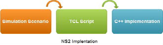
NS2 is a discrete event simulator targeted at networking re- search. Provides substantial support for simulation of TCP, routing, and multicast protocols over wired and wireless (local and satellite) networks. It is primarily UNIX based.
IJSER © 2014 http://www.ijser.org
International Journal of Scientific & Engineering Research, Volume 5, Issue 1, January-2014 782
ISSN 2229-5518
Fig. 4 NS2 Implementation
In this paper validation of basic network model and simula- tion of different network scenario’s done using ns2, because it is scientifically verified and recommended by research com- munity worldwide.
5.2 Gnu plot
Gnu plot is a command-driven interactive function plotting pro- gram. It can be used to plot functions and data points in both two- and three-dimensional plots in many different formats. It is designed primarily for the visual display of scientific data.
It is software for making 2D and 3D graphs from data and func- tions. Gnu plot supports lots of output formats, including drivers for many printers, (La) TeX, (x) fig, Postscript, and much more. It is frequently used for publication-quality graphics as well as edu- cation. The program runs on all major computers and operating systems such as GNU/Linux, UNIX, Microsoft Windows, Mac OS, and others. Gnuplot can produce output directly on screen, or in many formats of graphics files, including Portable Network Graphics (PNG), Encapsulated PostScript (EPS), Scalable Vector Graphics (SVG), JPEG and many others. The program can be used both interactively and in batch mode using scripts. The pro-
gram is well supported and documented.
6 SIMULATION SCENARIO AND OBTAINED RESULTS
6.1 Basic Validation Model
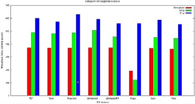
6.1.1 Network Congestion Scenario
In this scenario, we create a congested node at the middle of the five-node topology by generating three TCP data traffic flows that must pass by this intermediate node to reach the other com- municating end. One should also note that, different levels of data
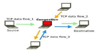
Fig. 5 Congestion Network Scenario
Gnuplot is used as the plotting engine of GNU Octave, Maxima and gretl, and it can be used from various scripting languages, including Perl, Python, Java, Ruby, Ch, and Smalltalk.
5.3 Edraw Max
Edraw Max, vector-based diagramming software, allows us- ers to create flowcharts, organizational charts, workflow dia- grams, software diagrams, network diagrams and more. Edraw's ease of use makes it particularly suitable for users who need to create professional quality drawings quickly and simply, without having to invest time in learning to use a complex application.
It enables students, teachers and business professionals to reliably create and publish kinds of diagrams to represent any ideas so we have used Edraw Max for drowing the various diagrams.
5.4 AWK scripting language
The AWK utility is an interpreted programming language typ- ically used as a data extraction and reporting tool. It is a standard feature of most Unix-like operating systems.
AWK is a language for processing text files. A file is treated as a sequence of records, and by default each line is a record. Each line is broken up into a sequence of fields, so we can think of the first word in a line as the first field, the second word as the second field, and so on. An AWK program is of a sequence of pattern-action statements. AWK reads the input a line at a time. A line is scanned for each pattern in the pro- gram, and for each pattern that matches, the associated action is executed. In our simulation we have used AWK programs to process and obtain result fromtrace and NAM file.
Fig. 5 Histogram of throughput, delay and packet drop of
Different tcp variants in congestion network scenario
TABLE 1 Values of Congestion Scenario
IJSER © 2014 http://www.ijser.org
International Journal of Scientific & Engineering Research, Volume 5, Issue 1, ISSN 2229-5518
Congestion can be generated by controlling the number of TCP data flows crossing this particular network node at a cer- tain time. The congested network is tested using Tcl script with different TCP variants as traffic agent and ploted histo- gram which is showing throughput, delay and drop packets for each variant.
6.1.2 Link failure Scenario
In this model we force TCP to change its communication path way by moving one intermediate node which acts as router out of signal reception range between the communicating end points. In addition, it implies routes with different number of hops. Thus, each time TCP changes the communication route, the characteristics of the path between the communicating nodes changes. It is obvious that the choice and the establish- ment delay of the new route will be dependent on the imple- mented ad hoc routing protocol. Packet losses and delay changes will also be implied by the link loss and the new cho- sen route. We notice that the effect of such networks nodes’ mobility can be represented by the link failure scenario de- scribed above as it is the most direct consequence of mobility.
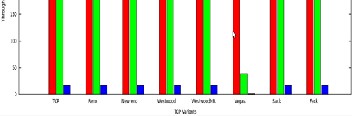
Fig. 6 Histogram of throughput, delay and packet drop of
Different tcp variants in Link failure Network Scenario
TABLE 2 Values of Link Failure scenario
Variant | Throughput | Delay | Drop Packet |
TCP | 374.09 | 226.1 | 17 |
Reno | 374.09 | 226.1 | 17 |
New Reno | 374.09 | 226.1 | 17 |
Westwood | 374.09 | 226.1 | 17 |
WestwoodNR | 374.09 | 226.1 | 17 |
Vegas | 193.36 | 39.093 | 1 |
Sack | 374.09 | 226.1 | 17 |
Fack | 374.09 | 226.1 | 17 |
6.1.3 Signal Loss Scenario in Network
This scenario illustrates the situation where the wireless signal is not stable. The communicating nodes loose the connection
due to signal loss and resume the communication when the
signal comes back. Signal losses are generated by moving one of the intermediate nodes out of the radio range of its connec- tion neighbors. This scenario created using three nodes end node acts as sender and receiver and intermediate node as router. Transmission of ftp traffic source flow through an in- termediate node, Intermediate node moves away for few se- cond so signal loss occurs between source and destination, after few second intermediate node moves at original place and again retransmission starts.
Fig. 5 Link failure Scenario in Ad-Hoc Network 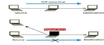
Fig. 7 Signal loss Scenario in Ad-Hoc Network
TABLE 3 Value of signal loss scenario
IJSER © 2014 http://www.ijser.org
International Journal of Scientific & Engineering Research, Volume 5, Issue 1, January-2014 784
ISSN 2229-5518
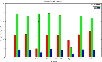
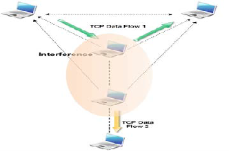
Fig. 6 Histogram of throughput, delay and packet drop of
Different tcp variants in Signal Loss Network Scenario
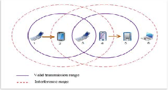
6.1.4 Interference Scenario in Ad-hoc Network
In this scenario, two TCP connections are established in paral-
lel.The main TCP connection is disturbed by the interferences
generated by the second TCP connection. Indeed, the node
acting as forwarder for the main TCP connection is placed
within the interference range of the second TCP connection
sender. So, this situation creates interference and thus data
packet losses. Interference scenario in wireless environment
created using two traffic sources; Transmission of second traf-
fic source will interfere to the first traffic source.
TABLE 4 Values Interference Scenario
Fig. 7 Intetrference Scenario in Ad-Hoc Network
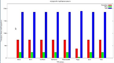
Fig. 8 Histogram of throughput, delay and packet drop of
Different tcp variants in Interference Network Scenario
TABLE 5 Simulation Parameters Values
Parameter | Values |
Channel Type | Wireless channel |
Radio Propagation Model | Two Ray ground |
Queue type | Droptail/PriQue |
Max. packet(buffer size) | 50 |
Network interface | Wirelessphy |
MAC Protocol | 802.11 |
Data Rate | 1 Mbps |
Transmission Radius | 250 |
Interference Radius | 550 |
IJSER © 2014 http://www.ijser.org
International Journal of Scientific & Engineering Research, Volume 5, Issue 1, January-2014 785
ISSN 2229-5518
.2.2 Grid multi-hop Ad-Hoc Network
6.1 Main Simulation Scenarios
6.2.1 Chain multi-hop Network
The chain network created with five hopes and six nodes to conduct simulation experiments.
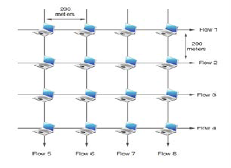
IJSEFig. 11 Grid toRpology in multihop Ad-Hoc Network
Fig. 9 Chain topology in multihop Ad-Hoc Network
The network consists of variable length chain of static nodes, placed at a distance of 200m from one another. FTP traffic is transferred between the first and last node of the chain shown in (Fig. 9). During the simulation different TCP variant at- tached as agent at the transport layer for the same scenario. One FTP connection kept active at a time and sequential TCP connection are initiated and terminated.
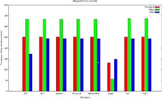
Fig. 10 Histogram of throughput, delay and packet drop of
Different tcp variants in Chain Topology
TABLE 6 Values for Chain Topology
Fig. 11 shows a static grid Ad-hoc network as experiment
topologycal network with 16 nodes. In a stationary environ- ment without mobility, the distance between two adjacent nodes is set to be 200 m, and the transmission and interference radii are set to 250 and 550 m, respectively. In each row, a TCP connection is assumed to set up from the left end node to the right end, and similarly, in each column, a TCP connection is assumed to set up from the top end node to the bottom end node.
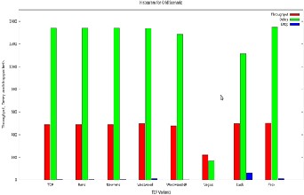
Fig. 12 Histogram of throughput, delay and packet drop of
Different tcp variants in Chain Topology
TABLE 7 Values for Grid Topology
Variant | Throughput | Delay | Drop Packet |
IJSER © 2014 http://www.ijser.org
International Journal of Scientific & Engineering Research, Volume 5, Issue 1, January-2014 786
ISSN 2229-5518
Raisinghani who has boosted morale, confidence and taught how to do research, my friend Prof. Sanjay Sange for constant- ly encouragement, motivation and helps for best quality work. at last but not least to my father who has shown such a glori- ous days.
REFERENCES
[1] Pratap K. Meher and P. J. Kulkarni, “Analysisand and Comparision of Performance of TCP-Vegas in MANET,” IEEE International Con- ference on Communication systems and network Technologies, pp.
67-70, 2011.
[2] Mandakini Tayade, Sanjeev Sharma,”review of different tcpVariants in ad-hoc networks,” International journal of Engineering Science and Technology, Vol.3 No. 3 pp. 1906-1913, March 2011.
[3] Marc Greis‘Tutorial for the UCB/LBNL/VINT Network Simulator
―ns‖. http://www.isi.edu/nsnam/ns/tutorial/
[4] B. Qureshi, M. Othman and N.A.W. Hami,”Progress in various TCP
variants,” IEEE, February 2009.
[5] Dhananjay Bisen and Sanjeev Sharma,”Improve Performance of TCP New Reno over mobile Adhoc Network using ABRA,” International Journal of wireless & Mobile Network, Vol. 3, No. 2, pp. 102-111, April 2011.
[6] Kevin Fall and Sally Floyd, “Simulation-based Comparisons of Ta- hoe, Reno, and SACK TCP,” ACM Computer Communication Re- view, pp. 5-21, 26(3) (1996).
[7] Jitender Sharma and Amit Kumar Garg “Analysis of Tahoe: A TCP
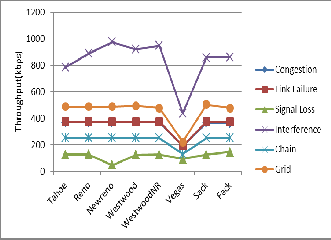
Fig. 13 Throughput plot fop TCP variants in all
Network scenario
7 CONCLUSION
Analysis of various TCP variants has been carried out based on the problems and proposed enhancements to find out pros and cons of each variant. It reveals that there is no single variant which can handle all problems such as congestion, link failure, signal loss, interference. Also it neither gives optimized through- put nor performs efficiently over chain and grid network scenari- os. Most of these variants are best in particular scenarios whereas the performance is lagging in some other MANET scenarios. Referring to the ns2 based simulated results, it is observed that proactive and bandwidth estimation based variants shows better handling to the mobility and frequent link failures whereas many of the TCP-variants show poor handling to changing network conditions. Thus it can be concluded that; the area is still open for research and the TCP-variants which are proactive and based on bandwidth estimation are more effective. Hence these parameters need to be taken into consideration for further investigation to obtain unique, reliable, robust, efficient TCP-variant and need to be further explored to make it suitable for adapting over mobile ad hoc networks.
ACKNOWLEDGMENT
I am deeply thankful to my M. Tech. Mentor Dr. Vijay
Variant” International Journal of Engineering and Advanced Tech- nology (IJEAT) ISSN: 2249 – 8958, Volume-1, Issue-2, December 2011.
[8] Saleem-ullah Lar, Xiaofeng Liao and Songtao Guo, “Modeling TCP NewReno Slow Start and Congestion- Avoidance using Simulation Approach,” International Journal of Computer Science and Network Security, VOL.11 No.1, January 2011. Technical Report IAM-02-003, Univ. of Bern, July 2001.
[9] Ahmod Al hambli et al.,”A survey of TCP over Adhoc Networks,” Communications Surveys & Tutorials, IEEE, vol. 7 pp. 22-36, 2005.
[10] Adib M. Monzer Habbal,“Loss Detection and Recovery Techniques for TCP in mobile Adhoc Network,”IEEE, second international Con- ference on Network Application, protocols and services, pp. 48-54,
2010.
[11] Dinesh C. Dobhal and Rakesh Sharma,”Simulation base analysis of TCP Reno and TCP Westwood over IEEE 802.11 wireless Adhoc Networks,” International Journal of Computer Science and Commu- nication, vol. 1, No. 2, pp. 383-386, December 2010.
[12] Suhas Waghmare et al,”Comparative Analysis of different TCP vari-
ants in a wireless environment,” IEEE, pp. 158-162, March 2011. [13] Amit M. Sheth et al, “Analysis Of TCP WestwoodNR Protocol in
[14] Congested and Lossy Network,” International Journal of Engineering
Trends and Technology- Volume4 Issue3, pp 477-482, 2013.
AUTHORS PROFILE
Prakash B. Khelage received his B.E. in Electronics and Telecommunica- tion Engineering from Dr. Babasaheb Ambedkar Marathwada University Aurangabad, M.Tech in information Technology from NMIMS University Mumbai, Maharastra, India. He is
IJSER © 2 http://www.ij
International Journal of Scientific & Engineering Research, Volume 5, Issue 1, January-2014 787
ISSN 2229-5518
currently working as Assistant Professor with UMIT, SNDT Women’s University. He has 13 years of experience in indus- trial as well as educational field; His research interest includes Ad Hoc Networks, Mobile Computing, Wireless Networks, Co-operative Communication Networks and Network Securi- ty. He has also interest in Computer Architecture design, Cloud Computing and Data Mining.
Uttam D. Kolekar received his B.E. in Electronics and Tele- communication Engineering, M.E. in Electronics from Shivaji University, Kolhapur and Awarded Ph. D. in electronics from Bharati Vidhyapith Pune, Maharastra, India. He is currently working as Principal with Smt. Indira Gandhi College of En- gineering, Mumbai University. He has more than 20 years of experience in educational institution; His research interest includes Ad Hoc Networks, Mobile Computing, Wireless Networks, Neural Network and Co-operative Communication Networks. He has published over 30 National and Interna- tional Jurnals & conferences various papers accros India and other countries.
IJSER

IJSER © 2014 http://www.ijser.org