International Journal of Scientific & Engineering Research, Volume 6, Issue 4, April-2015 1678
ISSN 2229-5518
Study the Increasing of the Cantilever Plate
Stiffness by Using Stiffeners
Jawdat Ali Yakoob Iesam Jondi Hasan
Ass. Prof. Ass. Lectu.
Ref. & Air. Cond. Dept/ Technical College / Kirkuk – Iraqـ
In this work, by using of finite element method analysis and exact analysis for thin plate theory, five different shape stiffeners are considered, including square, triangle, trapezoidal and T-section with two different thicknesses. For more easily analysis the plate behavior considered as beam behavior because the plate width is very small in compare with the plate length. For all stiffener types, at first the length, thickness and width of the plate are assumed constant and the area of stiffeners added to the plate section, then in the second case the cross section area of the plate with and without stiffeners assumed as constant, (i.e., the cross section area of the plate and stiffener equal to the flat plate cross section area).
The results showed that the adding of the stiffeners with each geometry shape and size to the plates are increased the plate stiffness. The plate with square stiffener become stiffer than others, but with more added mass and area. The 1mm T-shape stiffener gave stiffness near to the equivalent rectangular plate with lower added mass and area.
—————————— ——————————
orthotropic materials by newly developed energy-based method.
The reinforced plates are often used in
engineering practice because they are stiff,
strong, stable and proportionally light. Typical areas of application of such plates are in many fields, such as cars structure, aircrafts, ships, tanks and in many supporting frames. Many industrial elements are made as thin panels reinforced by stiffeners. The stiffeners are different in their geometry, size, cross-section area and mass, and then the choice of an optimal one is important to obtain the required stiffness with keeping the weight of the structure as low as possible.
Adding of stiffener significantly affects the static characteristics of the structure hence it has a direct interest in structure design. Luo and Gea [1], proposed to design the optimal stiffener with three - dimensional trapezoidal shell/plate structure for static and eigenvalue proplems. The stiffener location problem is solved by a microstructure-based design domain method and the orientation problem is modeled as an optimization orientation problem of equivalent
Jarmai & Farkas [2], are studied the minimum cost design of uniaxially compressed plates with welded trapezoidal stiffeners considering the buckling failures. It has been taken the design constraints as global, local and torsional buckling and the limitation of the thickness of cold-formed trapezoidal stiffeners and limitation of the distortion caused by shrinkage of welds. They take the global buckling constraint into account due to the given deviation in different parameters. The optimum dimensions of stiffeners and their numbers are determined by mathematical programming method.
Alinia [3], analyzed a group of 1200 plates by
using ANSYS finite element method of analysis to study the role of longitudinal stiffeners to come up with some limits concluded for an optimized design procedure. He is investigated that the number of panels produced by intermediate transverse stiffeners should not be less than the value of plate's aspect ratio. Also the optimum geometric properties of the stiffeners correspond to the point when the
IJSER © 2015 http://www.ijser.org
International Journal of Scientific & Engineering Research, Volume 6, Issue 4, April-2015 1679
ISSN 2229-5518
buckling shape of a plate changes from the overall mode to local mode.
Yahya [4], obtained an economical design of plate loaded by pressure using rectangular
stiffeners. The effect of stiffeners height on the maximum stress in the plate subjected to
pressure load was obtained. To find the effect of stiffeners thickness, plate dimensions, and
pressure on the optimum stiffeners height and different sets of plate-stiffeners combinations are
selected, using FEM software package ANSYS.
Nildem [5], considered the buckling
optimization of stiffened plates under uniform edge compression. The design variables considered as the stiffeners location and its effect on the critical buckling load. Investigated two types of stiffened plates are used in aerospace industry. From the results, the influences of size optimizations and stiffeners location are presented to develop and improve the design for stiffened plates.
Szczepanik and Burczynski [6], are studied
the swarm methods and the finite element method to optimize the stiffeners location in the
2-D structure. The criteria's of the optimized structure are stress and displacement. From
numerical technique they found that the effective technique for solving the computer aided optimal
design is the method based on the swarm computation. They present additional
comparisons of the effectiveness of the particle swarm optimizer (PSO) and evolutionary algorithms (EA) methods.
In the present study, the effect of adding single stiffener with deferent geometries to long
cantilever plate as rigid coupling is investigated. Finite element method is used to analyze the
bending behavior of the plates due to the acted load on free tip. Five solid stiffeners with
deferent geometries are considered, including square, triangle, trapezoidal, and two T-section
stiffeners (1 and 2 mm) thickness.
Plate is a flat surface having large dimensions as compared to its thickness. The plate behavior in steady static bending condition approximately likes to the beam behavior when the plate width is very small when compared with the plate length. The bending properties of a plate depend greatly on its thickness. Hence; in classical theory there are thin and thick plates and thin
plate has two sub-theories, small and large deflection theories. In thin plates with small deflections theory, the following assumptions are considered [7]:
(a) There is no deformation in the mid-surface plane of the plate. This plane remains neutral during bending.
(b) Points of the plate lying initially normal to
the middle surface of the plate remain normal to the same surface even after bending.
(c) The normal stresses in the transverse direction to the plate are negligible.
This theory is satisfactory for plates with thickness to length ratio exceeding (1/10) and the
ratio of maximum deflection to the thickness less then (1/5). Many engineering problems lie under
the above conditions and satisfactory results are obtained by classical theories of thin plates.
For cantilever plate there is one free end and other clamped end. The cantilever plate will
bend laterally when a normal force is acting on the free end tip, this bending depends on plate
dimensions, material, and force value. In many engineering examples bending deformation is
needed to be reduced. One of the common methods is by reinforcing the plate by using
stiffeners instead of increasing plate thickness, and the effect of the stiffeners on the plate
bending behavior depends on the dimensions and geometry of the stiffeners, in addition to the
method of clamping between the plate and stiffeners.
The using of different geometries of single
stiffener to reinforce cantilever plate as a rigid clamping along the plate is included in the present study to determine the optimum stiffeners geometry with low added mass, and analyzing of plate bending value numerically using finite element method then comparing it with exact bending theory.
A thin rectangular plate is considered as shown in figure (1) for the static bending of rectangular plate. The plate is assumed to follow the classical beam bending. The plate's length along x direction, width along y direction and thickness along z direction, hence the plate is assumed to lie in the x-y plane. The plate has two independent displacements (i.e., displacement in y direction and rotation around z axis). The rectangular cross section plates with
IJSER © 2015 http://www.ijser.org
International Journal of Scientific & Engineering Research, Volume 6, Issue 4, April-2015 1680
ISSN 2229-5518
different shaped stiffeners are shown in figure(2).

Width
will be as shown in the figure (3); where the plates thickness are reduced according to the added stiffener cross section area to keep the plate mass constant in all types.
Thickness
(1000 mm length)
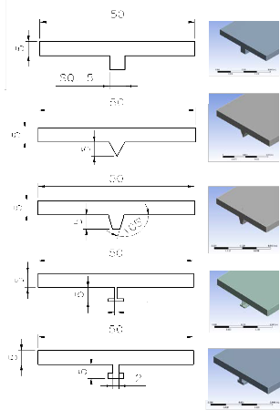
Figure (1): Flat rectangular plate
(a)
(b)
(c)
(a)
(b)
(c)
(d)
(d)
(e)
Figure (2): Rectangular Plate with Different Shape
Stiffeners. (1000 mm length for all)
The stiffeners are lied on the related plates such that length of the stiffeners is parallel to the length of the plates. The stiffeners and the plates are assumed to have rigid coupling at their connecting interface.
The stiffeners assumed to have the same whole boundaries (i.e., 5mm whole width and
5mm whole thickness). In this case the stiffeners
cross section areas are added to the flat plate cross section area, then the plates mass are increased. In the second case, the cross section area of the plate with and without stiffeners is
considered constant, then the plates mass are
(e)
Figure (3): Stiffened Plates with Constant Cross Section.
The plates and stiffeners are assumed to be made of steel with Modulus of Elasticity (E = 200
GPa), Poisson's ratio (v = 0.3) and Density (ρ =
7830 kg/m3).
All plates have the same boundary conditions as cantilever plate (i.e., clamped from one side and free from other side). The plate bending theory is very complex, but whereas the plate width is very small in comparison with the plate length, then the plate can be assumed as a beam, where the more easy beam bending theory can be applied, and in this case the beam bending theory will give accurate results, specially when the plates bend in one plane, (i.e., x-y plane). The plates bends due to lateral force act at their free ends, and then from the strength theory of material, the total deflection (δ) at the free end can be calculated from equation (1) for cantilever beam as [8]:
3
remained constant. Then the plates dimensions
IJSER © 2015 http://www.ijser.org
![]()
𝛿 = 𝑊×𝐿
3×𝐸×𝐼
(1)
![]()
International Journal of Scientific & Engineering Research, Volume 6, Issue 4, April-2015 1681
ISSN 2229-5518
Where, (W) is lateral force at the plate tip, (L) is plate length and (I) is moment of inertia of the cross
section area of the plate. For all plates made of the same material and have the same length, then in equation (1) the lateral force, plate length, and
modulus of elasticity are constants, therefore, the formula (W×L3/3×E) will be constant, and the moment of inertia changes with the change of the cross section of the plate. Then the moment of inertia (I) can be assumed to represent the bending parameter. On the other hand, when the plates made of different materials but have the same length, then the formula (W×L3/3) will become constant, and the formula (E×I) is assumed to represent the bending parameter. Then the equation can be used to calculate the deflection of any plate or beam by changing the bending parameter only.
Figure (4): n-element cantilever plate model and node definition
For static deflection the element stiffness matrix can be developed by using basic strength of materials technique to analyze the required force to move each degree of freedom a unit value in the positive direction. Then the stiffness matrix for element (i) will take the form [9]:
The moment of inertia of the cross section area of the plate will change with adding the
![]()
12
⎡ 𝑙𝑖![]()
6
𝑙𝑖
![]()
−12
𝑙𝑖
![]()
6
𝑙𝑖 ⎤
⎢ 6 4 −6 2 ⎥
stiffeners to the plate, therefore, the deflection of
![]()
⎢ 𝑙2
𝑙𝑖
𝑙2
![]()
![]()
![]()
𝑙𝑖 ⎥
the stiffened cantilever plate due to lateral force
𝑘𝑒,𝑖 = 𝐸𝑖 𝐼𝑖 ⎢
𝑖
−12
𝑖
−6 12
−6⎥
(2)
acting at the free end can be calculate by
![]()
⎢ 𝑙3
𝑙2
![]()
![]()
𝑙3
![]()
𝑙2 ⎥
substituting the moment of inertia of the flat
𝑖 𝑖 𝑖 𝑖
⎢ 6 2 −6 4 ⎥
plate cross section area with the new moment of
inertia including the cross section of the
stiffener. The moments of inertia for the two
![]()
⎣ 𝑙𝑖
𝑙𝑖
𝑙𝑖
![]()
![]()
![]()
𝑙𝑖 ⎦
cases of stiffened plates are given in the table
(1).
Table (1): Moment of Inertia for All Plates.
4
The plates are divided to (n) elements, each element has two nodes, and each node has two degrees of freedom including displacement (Z) and rotation (θ) as shown in figure (4).
Where, (kRe,iR) is element stiffness matrix, (ERiR) is modulus of elasticity of the element material, (IRiR) is moment of inertia for the cross section area of the element and (lRiR) is element length. Then to build the global stiffness matrix (kRgR) for the plate, the start age will be with (n×n) null matrix, then building up the global stiffness matrix by inserting element after element according to the degree of freedom for each node. In the case of cantilever plate, the degree of freedom of the first node for element (1) is neglected.
For static deflection of cantilever plate due to lateral force (F) act at the tip of the free end the displacement in (Z) direction can be solved. The equation for static equilibrium of the plate is:
kRgR × Z = F (3) Where (kR gR) stiffness matrix, (Z) deflections
matrix and (F) it will be forces matrix.
by expanding the equation (3):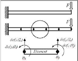
IJSER © 2015 http://www.ijser.org
International Journal of Scientific & Engineering Research, Volume 6, Issue 4, April-2015 1682
ISSN 2229-5518
⎡ 𝑘𝑔11 𝑘𝑔12
… … … . .
0 0 ⎤ ⎡
𝑍1
𝑍2 ⎤
𝐹1
⎡ 𝐹2 ⎤
cantilever plate deflection due to the lateral
⎢ 𝑘𝑔21 2𝑘𝑔22
−
0 0 ⎥ ⎢
⎥ ⎢ ⎥
forces acting at the free end are increased with
⎢ ⎥ ⎢ —
⎥ = ⎢ —
⎥ (4)
decreasing the moment of inertia as shown in
⎢ − ⎥ ⎢ − ⎥
⎢ − ⎥
figure (5) for case (1), and figure (6) for case (2).
⎢0 0
2𝑘𝑔(𝑛−1)(𝑛−1) 𝑘𝑔(𝑛−1)𝑛 ⎥ ⎢𝑍(𝑛−1) ⎥
⎢𝐹(𝑛−1) ⎥
⎣0 0
𝑘𝑔𝑛(𝑛−1) 𝑘𝑔𝑛𝑛 ⎦ ⎣
𝑍𝑛 ⎦
⎣ 𝐹𝑛 ⎦
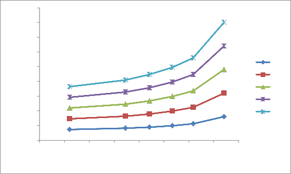
The increase of the deflection average with
increasing the force value for the stiffed plate
Where (Z1 & Z2 , ………., Z(n-1) & Zn )
represents the translation and rotation of nodes
with numbers (1, 2, ………., n) respectively, and
(F1 , F2 , ……., F(n-1), Fn ) represents the applied forces on each node. To find each node displacement the inverse of the global stiffness matrix (kg) must be calculated, and equation (3) will become:
-1
which has less moment of inertia value was more
than the plate has more moment of inertia value.
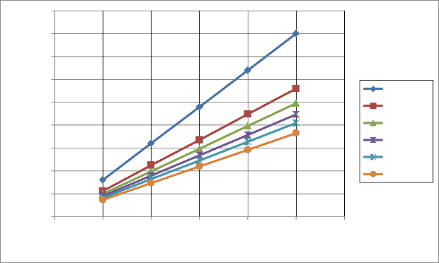
The comparison of bending deformation of the cantilever plates for case (1) is shown in the figure (7), it can be observed that the plate with rectangular stiffener showed lowest deflection with highest moment of inertia, but the plate with triangular stiffener showed highest deflection with lowest moment of inertia. On the
other hand, the square stiffener is associated with
Z = (kRgR)
× F (5)
highest equivalent added mass, but the triangular
In the case of cantilever plate with lateral applied force at the free end, all forces value for the forces matrix is equal to zero except (FRnR) which equal to the applied force at the free end.
The solving of the equation (5) performed by using Matlab program. Also the finite element models of all plates are generated by ANSYS software using the Solid45 element. This element is used for generating and meshing solid body; it has four sides, eight nodes and three degree of freedom for each node. The static bending analysis is performed for all cantilever plates.
The static bending analysis is performed for the flat plate and stiffened plates which have one clamped end and the other free end by applying lateral force at the free ends. The lateral applied forces are (10, 20, 30, 40 and 50 N) respectively. The results of five deformation for all six plates types including case (1) and (2) are compared as shown in the tables (2) and (3). It is observed that with addition of stiffener of any type or size tend to increase in the stiffness of the plate in such away more than that of the plate without stiffener.
The effective parameter for cantilever plate
bending is the moment of inertia (I), where the
stiffener is associated with lowest equivalent added mass. For stiffened plates, the square stiffener associated with highest added mass, but the 1mm-T stiffener associated with lowest added mass. Table (4) shows the equivalent flat plate thickness, the added area and added mass caused by using each stiffener type. Where the
1mm-T stiffener has the lowest stiffener added area and lowest ratio between the stiffeners to equivalent added area for equivalent plate.
In the case (2) where the cross-section area
and mass of all plates remained constant with and without using stiffeners, the deflection for all plates is shown in the figure (8). In this case the increasing of the plate stiffness was less than those belong to case (1), but without adding additional mass to the plate. Also as in case (1) the stiffness of the plate became larger than un- stiffened plate.
Table (2): Stiffened cantilever plate deflection for case (1).
Force (N) | Plates with Stiffeners Type | Plate without stiffener | With Square Stiffener | With Triangular Stiffener | With Trapezoidal Stiffener | With 1mm-T Stiffener | With 2 mm-T Stiffener | |
10 | lecti on | Exact | 0.032 | 0.0146058 | 0.0223755 | 0.0178606 | 0.0198003 | 0.0163818 |
IJSER © 2015 http://www.ijser.org
International Journal of Scientific & Engineering Research, Volume 6, Issue 4, April-2015 1683
ISSN 2229-5518
FEM | 0.032 | 0.0146 | 0.0224 | 0.0179 | 0.0198 | 0.0164 | ||
ANSYS | 0.031778 | 0.014553 | 0.022253 | 0.017786 | 0.019712 | 0.017366 | ||
20 | Exact | 0.064 | 0.0292116 | 0.0447503 | 0.0357212 | 0.3960065 | 0.0327636 | |
20 | FEM | 0.064 | 0.0292 | 0.0448 | 0.0357 | 0.0396 | 0.0328 | |
20 | ANSYS | 0.063557 | 0.029105 | 0.044506 | 0.035571 | 0.039423 | 0.034733 | |
30 | Exact | 0.096 | 0.0438175 | 0.0671255 | 0.0535818 | 0.0594010 | 0.0491455 | |
30 | FEM | 0.096 | 0.0438 | 0.0671 | 0.0536 | 0.0594 | 0.0491 | |
30 | ANSYS | 0.095335 | 0.043658 | 0.066759 | 0.053357 | 0.059135 | 0.052099 | |
40 | Exact | 0.128 | 0.0584233 | 0.0895006 | 0.0714425 | 0.0792013 | 0.0655273 | |
40 | FEM | 0.128 | 0.0584 | 0.0895 | 0.0714 | 0.0792 | 0.0655 | |
40 | ANSYS | 0.12711 | 0.058211 | 0.089013 | 0.071143 | 0.078846 | 0.069466 | |
50 | Exact | 0.16 | 0.0730291 | 0.1118758 | 0.0893031 | 0.0990016 | 0.081909 | |
50 | FEM | 0.16 | 0.0730 | 0.1119 | 0.0893 | 0.0990 | 0.0819 | |
50 | ANSYS | 0.15889 | 0.072763 | 0.11127 | 0.088928 | 0.098558 | 0.086832 | |
Rip Area (mm2) | - | 25 | 12.5 | 18.3 | 9 | 16 |
Table (3): Equivalent plate thickness and added stiffeners area for case (1).
Stiffener Type | Equivalent Thick. (mm) | Added Thick. (mm) | Equivalent Added area (mm2) | Added Stiffener area (mm2) | Stiffener /Equivalnet (%) | Added Stiffener mass (%) | |
1 | Flat | 5 | 0 | 0 | 0 | 0 | 0 |
2 | Square | 6.493986757 | 1.493986757 | 74.69933785 | 25 | 33.4674988 | 10 |
3 | Triangle | 5.633323497 | 0.633323497 | 31.66617485 | 12.5 | 39.47429729 | 5 |
4 | Trapezoidal | 6.072784712 | 1.072784712 | 53.6392356 | 18.3 | 34.11681728 | 7.32 |
5 | 2mm T | 6.250277353 | 1.250277353 | 62.51386765 | 16 | 25.59432107 | 6.4 |
6 | 1mm T | 5.867278 | 0.867278 | 43.3639 | 9 | 20.7545908 | 3.6 |
Table (4): Stiffened cantilever plate deflection for case (2).
IJSER © 2015 http://www.ijser.org
International Journal of Scientific & Engineering Research, Volume 6, Issue 4, April-2015 1684
ISSN 2229-5518
Force (N) | Plates with Stiffeners Type | Plate without Stiffener | With Square Stiffener | With Triangular Stiffener | With Trapezoidal Stiffener | With 1mm-T Stiffener | With 2 mm-T Stiffener | |
10 | Deflection (m) | Exact | 0.032 | 0.01774 | 0.02533 | 0.02093 | 0.02142 | 0.01861 |
10 | Deflection (m) | FEM | 0.032 | 0.0177 | 0.0253 | 0.0209 | 0.0214 | 0.0186 |
10 | Deflection (m) | ANSYS | 0.031778 | 0.017682 | 0.025197 | 0.020882 | 0.021329 | 0.018653 |
20 | Deflection (m) | Exact | 0.064 | 0.03548 | 0.05067 | 0.04186 | 0.04285 | 0.03723 |
20 | Deflection (m) | FEM | 0.064 | 0.0355 | 0.0507 | 0.0419 | 0.0428 | 0.0372 |
20 | Deflection (m) | ANSYS | 0.063557 | 0.035363 | 0.050394 | 0.041764 | 0.042658 | 0.037306 |
30 | Deflection (m) | Exact | 0.096 | 0.05322 | 0.0760 | 0.06278 | 0.06427 | 0.05584 |
30 | Deflection (m) | FEM | 0.096 | 0.0531 | 0.0760 | 0.0628 | 0.0643 | 0.0558 |
30 | Deflection (m) | ANSYS | 0.095335 | 0.053045 | 0.075591 | 0.062645 | 0.063986 | 0.055959 |
40 | Deflection (m) | Exact | 0.128 | 0.07097 | 0.1013 | 0.08372 | 0.08569 | 0.07445 |
40 | Deflection (m) | FEM | 0.128 | 0.0710 | 0.1013 | 0.0837 | 0.0857 | 0.0744 |
40 | Deflection (m) | ANSYS | 0.12711 | 0.070727 | 0.10079 | 0.083527 | 0.085315 | 0.074611 |
50 | Deflection (m) | Exact | 0.16 | 0.08871 | 0.1267 | 0.10464 | 0.10712 | 0.09306 |
50 | Deflection (m) | FEM | 0.16 | 0.0887 | 0.1267 | 0.1045 | 0.1071 | 0.0931 |
50 | Deflection (m) | ANSYS | 0.15889 | 0.088408 | 0.12599 | 0.10441 | 0.10664 | 0.093264 |
Rip Area (mm2) | - | 25 | 12.5 | 18.3 | 9 | 16 |
Table (5): Equivalent plate thickness and stiffener areas for case (2).
Type | Equivalent Thick. (mm) | Added Thick. (mm) | Equivalent Added area (mm2) | Stiffener area 2 (mm ) | Stiffener /Equivalent (%) | Stiffener mass (%) | |
1 | Flat | 5 | 0 | 0 | 0 | 0 | 0 |
2 | Square | 6.0865 | 1.0865 | 54.328 | 25 | 46.01678692 | 10 |
3 | Triangle | 5.40516 | 0.405156 | 20.2578 | 12.5 | 61.70462735 | 5 |
4 | Trapezoidal | 5.7601 | 0.7601 | 38.005 | 18.3 | 48.151559 | 7.32 |
5 | 2mm T | 5.9902 | 0.9902 | 49.5076 | 16 | 32.31827033 | 6.4 |
6 | 1mm T | 5.7158 | 0.7158 | 35.792 | 9 | 25.14528386 | 3.6 |
IJSER © 2015 http://www.ijser.org
International Journal of Scientific & Engineering Research, Volume 6, Issue 4, April-2015 1685
ISSN 2229-5518
0.18
0.16
0.14
0.12
0.1
0.08
0.06
0.04
10 N
20 N
30 N
40 N
50 N
0.02
0
400 500 600 700 800 900 1000 1100 1200
Moment Of Inertia (mm4)
Figure (5): Effect of moment of inertia on the plate deflection for case (1).
0.18
0.16
0.14
0.12
0.1
0.08
0.06
0.04
10 N
20 N
30 N
40 N
50 N
0.02
0
400 500 600 700 800 900 1000 1100 1200
Moment Of Inertia (mm4)
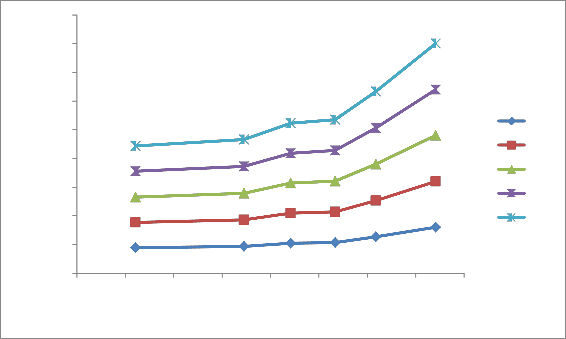
Figure (6): Effect of moment of inertia on the plate deflection for case (2).
IJSER © 2015 http://www.ijser.org
International Journal of Scientific & Engineering Research, Volume 6, Issue 4, April-2015 1686
ISSN 2229-5518
0.18
0.16
0.14
0.12
0.1
0.08
0.06
0.04
Flat
Triangle Rip
1mm-T Rip
Trap. Tip
2mm-T Rip
Square Rip
0.02
0
0 10 20 30 40 50 60
Force (N)
Figure (7): Plates Deflection for Case (1) for Each Stiffener Type.
0.18
0.16
0.14
0.12
0.1
0.08
0.06
0.04
0.02
Flat
Triangle Rip
1mm-T Rip
Trap. Tip
2mm-T Rip
Square Rip
0
0 10 20 30 40 50 60
Force (N)
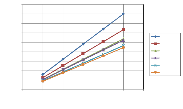
Figure (8): Plates Deflection for Case (2).
Conclusion
The static bending analysis for a plate without
stiffener and stiffened plates is performed.
Results of the analysis gave the following information regarding static bending of plates:
1- Addition of a stiffener to the plate with any
shape and size has an effect of increasing the
IJSER © 2015 http://www.ijser.org
International Journal of Scientific & Engineering Research, Volume 6, Issue 4, April-2015 1687
ISSN 2229-5518
plate stiffness to resist the bending due to lateral force.
2- The moment of inertia is the effective parameter on the plate bending (bending
parameter) for the plates made from the same material and with same dimensions.
3- The case of adding stiffener to the plate gave highest stiffness increasing in comparison
with the case of adding stiffener with remaining the plate mass constant with and
without stiffener.
4- The using of square stiffener caused the
highest increasing in the stiffness value but with highest added mass.
5- The 1mm-T type stiffener gave suitable stiffness to the plate with lowest added mass
in comparison with other stiffener types.
6- The triangular stiffener type has the lowest
equivalent plate thickness.
References
1- J. Luo and H.C. Gea. "A Systematic Topology
Optimization Approach for Optimal Stiffener
Design". Structural Optimization 16, © Springer – Velarg, 1998. pp. 280-288.
2- K. Jarmai & J. Farkas. "Minimum Cost
Design of Uniaxially Compressed Plates with
Welded Trapezoidal Stiffeners Considering a Reliability Constant". Metal Structures – Design, Fabrication, Economy, Jarmai & Farkas (eds) © 2003 Millpress, Rotterdam, ISBN 90-77017-75-5. pp. 209-210.
3- M.M. Alinia. "A Study Into Optimization of
Stiffeners in Plates Subjected to Shear
Loading". Elsevier Ltd. 2005. pp. 845-846.
4- Yahya Mohey Hamad. "Optimum Height of
Plate Stiffener Under Pressure Effect". The
1st Regional Conference of Eng. Sci. NUCEJ Spatial ISSUE Al-Nahrain University/
College of Engineering. Voll. 11, No. 3. 2008. pp. 459-460.
5- Nildem Taysi. "Determination of Thickness and Stiffener Location for Optimization of
Critical Buckling Load of Stiffened Plates".
Scientific Research and Essays Vol. 5(9), 4
May 2010. pp. 897-910.
6- M. Szczepanik and T. Burczynski. "Swarm
Optimization of Stiffeners Locations in 2-D Structures". Bulletin of the Polish Academy of Sciences Technical Sciences, Vol. 60, No.
2,2012. Pp. 241.
7- Timoshenko, S. and S. Woinowskky-Krieger. "Theory of Plates and Shells". McGraw Hill. pp. 21-46.
8- Khurmi, R. et al. "Theory of Machines", 14th
edition, S. Chand & Co. Ltd., New Dehli
2005;. pp. 919.
9- Saeed Moaveni. "Finite Element Analysis.
Theory and Application with ANSYS".
Prentice. Hall., Inc, 1999. pp.328-329.
IJSER © 2015 http://www.ijser.org