The research paper published by IJSER journal is about Solar Space Power Generation 1
ISSN 2229-5518
Solar Space Power Generation
1Gursimran Singh Sethi, 2Dhruv Mathur
Abstract- This paper gives guidelines illustrating the various components of the Solar Space Power Generation Program and to provide a d escription of a fundamental system that will help to power the cities on tomorrow removing the dependence on non-renewable sources of energy. Included is the structure for using the sun‟s energy and transmission of up to 185.88GW per day back to the Earth at a preliminary cost of $1 .577 billion. The literature also describes the economic implications of the launch, collection and transmission of the solar power program.
—————————— ——————————
1. INTRODUCTION
Energy is central to every economic, environmental, corporate, security and developmental issue in today’s world. Currently we are standing at a ‚bottle-neck‛ in the supply of energy to the economic system. There has been an enormous increase in the global demand for energy in recent years as a result of the large industrial development and population growth in both developing and developed
nations across the globe. In statistics, the global demand for
[1]
electricity causes the depletion of resources, which are non- renewable in nature and cause much contamination and pollution to the environment around us. This does not directly imply that the solution is non-renewable sources as these are quite inefficient in producing enough energy to compensate the cost of their own manufacture. The objective of Space based Solar Power generation therefore,
is to provide a clean, effective and economically viable
source of energy generation that could power the future generations even in the absence of fossil fuels. The goals of
energy will rise up to 40% in 2040
. Hence, supply of
this study are to assess the technological readiness and
energy is much less than the high demand for it. The supply of energy can be classified in two broad ways:
1. Conventional: Using non-renewable substances such as coal, petroleum, kerosene etc. as fuel to generate electricity.
2. Non-Conventional: Using the power of nature such as solar energy, tidal energy, wind energy, nuclear energy etc. to generate electricity.
As such there is no single energy challenge, thus this matter cannot be addressed in isolation. The inter-relationships between energy, environment and economy require a solution that satisfies all three aspects of the problem. For example usage of conventional sources to produce
————————————————
![]() Dhruv Mathur is currently pursuing bachelor’s degree program in
Dhruv Mathur is currently pursuing bachelor’s degree program in
Instrumentation & Control Engineering in Netaji Suhbas Institute of
Technology, Delhi University, India, PH-01126141642. E-mail:
mathdhruv@gmail.com
risks for space based solar power options. There has been a lot of research done over photovoltaic cells and their effectiveness over the past few decades but unfortunately we have not been able to come up with something as big, which could provide for a whole continent. Our nonrenewable oil/gas fuels will be depleted in another 40 to
60 years; coal will be depleted in about 300 to 500 years. Thus taking into account the stupendous increase in the usage of energy by the expected population of 8.8 billion by the year 2025 and to limit the greenhouse gas emissions in the atmosphere by the non-renewable fossil fuels, we have to somehow achieve the energy from renewable sources for the next 3 generations. The current rate of CO2 emissions[2] are sky-rocketing which implies that we will have to drive
90% of the energy from renewable sources the remaining
10% allowance only for big-scale industries. To derive such energy from only non-renewable sources, space solar
power generation seems a good idea. The following study
proves the efficiency of the system and explains its economic feasibility. The space solar generation program is a fairly large system and its methodology and working is
also explained in the literature. The two very big
IJSER © 2012 http://www.ijser.org
The research paper published by IJSER journal is about Solar Space Power Generation 2
ISSN 2229-5518
advantages of obtaining power from space are 24-hour
supply of sunlight and obtaining sunlight, which is pure and unfiltered by the atmosphere, which protects the Earth. Also unlike Earth where the sun is overshadowed by rain
or clouds and fog, space solar power generation is very efficient. The complex technologies involved in the solar space generation program including the transmission of power back to Earth and its synchronization with other existing solar power units is also explained in the study. Therefore, Space Solar Power (SSP) shall be the ultimate sustainable power source for all mankind’s energy needs.
Methodology:
Fig1. Explains the basic methodology required for any and all solar space generation programs. It gives a roadmap, which explains the various steps involved to harness the sun’s energy from space and send back to Earth.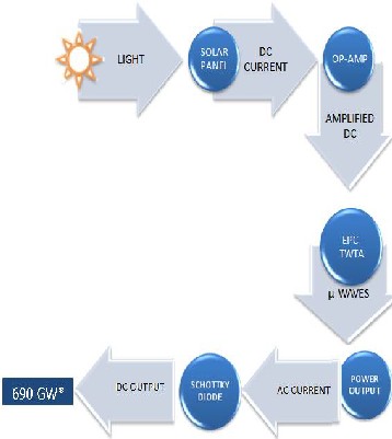
*Output Per week
Fig 1. Flow Diagram depicting SSP System
2. ARCHITECTURE OF THE SYSTEM
The Space Solar Power Generation Program comprises of 2
major units:
1. Space Station
2. Ground Station
2.1 Space Station
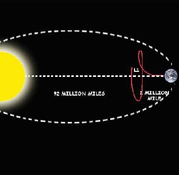
The space station for the massive solar generation will comprise of a satellite. This satellite named ‚Aditya‛ it translates to ‚Sun‛ .They will be placed in a Halo Orbit[3]in vicinity to the Lagrangian PointL1[4]. Previous studies and work exhibits the advantages of a halo orbit which is mainly the low cost relay[5].The selection of L1 was a difficult decision as it required testing of seemingly more favorable options such as L4&L5 or even Earth’s orbit. Although L1 lies on a point of unstable equilibrium as discussed, it is a drawback that we have to live with, like a
bitter but effective medicine. L4&L5 seemed quite favorable due to their highly stable orbit but they could not be adopted because of their large distance from the Earth which will give the transmission an appreciable time lag of roughly 8mins whereas the time lag from L1 is quite small (5s). Due to the distance, much more fuel would be
required to reach L4 (92 times). The literature below shows
that there is a need of transmitting energy to the earth in very small intervals at a particular station which would have been much more difficult in the case of the satellite being in the Earth’s orbit.L1 is the best place to observe the sun thus, the satellite shall always remain in the presence of sunlight and will collect energy from the sun using solar panels continuously hence booming the production of electricity. Unfortunately, some amount of extra fuel (10%) is required for course correcting because the equilibrium at L1 is not as perfect as L4& L5 but this fuel is generally leftover and can be utilized further on for about 100-120 years.
IJSER © 2012 http://www.ijser.org
The research paper published by IJSER journal is about Solar Space Power Generation 3
ISSN 2229-5518
The satellite will have 4 panels of solar cells each of area
2,500m2. This is very much feasible because of the new incoming technology of Silicon Microwire – Nanoneedle arrays[6][7].
In such arrays, the photovoltaic surface is made up of periodic arrangements of Silicon microwires, which are close to 70 microns in length, & only 1 micron in diameter, with small 5-micron long Nanoneedles co-integrated
between the longer, periodic microwires.
Fig2. Halo Orbit around Earth-Sun L1 point
The satellite comprises of 4 main parts- Solar Panels; Voltage amplification Unit; Fuel Storage; TWT (Travelling Wave Tubes) & Transmission Dish. They are described as follows.
Fig3. 3-D Render of Space Station Unit
These nanowires are encased in a transparent, inexpensive
polymer (such as PDMS), & are sparsely spread over a back reflector surface, which reflects back the sunlight which has not been absorbed by any of the ‘hairs’. The polymer is also dotted with light-scattering particles & anti-reflective surfaces, so that any light that does not enter a nanowire
the first time around gets scattered towards another one.
The anti-reflective surfaces prevent loss of light by reflection, which is a significant drawback in current solar cell designs.
Each of the Si nanowires is in itself a very efficient solar cell, & when coupled with the back reflector, the light- scattering surfaces & the anti-reflective coating in the polymer, can produce an absorption efficiency of up to
97.6% of incoming wavelengths from 300-1100 nm, for a Si microwire of 70 µm. Such a high efficiency is obtained by combining methods to prevent transmission & reflection of light, such as the GRI Effect, Back reflection, & the Plasmonic effect.
The cell itself will be made up of a mixed composition of about 98% of a transparent polymer, which is used as a casing, while 2% is the Silicon itself hence making it somewhat a precursor molecule unit. The usage of plastic polymers is an added advantage, as it not only lowers the cost of the cell by a significant amount, it also enables them to be flexible, which allows them to be used in many different configurations, as per the needs.
IJSER © 2012 http://www.ijser.org
The research paper published by IJSER journal is about Solar Space Power Generation 4
ISSN 2229-5518
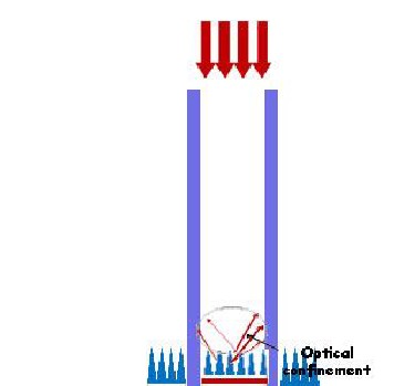
Fig 4. Optical Confinement in a Nanowire PV
Efficiency of conventional PV : 29% Resistance heat loss : 7%
Therefore, total efficiency: 1 x .29 x .93 = 0.2697(Assume
fraction of sunlight received on Earth=1)
% efficiency of PV = 26.97%
(Assume zero heat loss due to resistance, as at low temperatures of space, wires can be superconductors) Efficiency of Nanowire PV : 29%
Fraction of sunlight received: 1.44
Therefore total efficiency: 1.44 x .29 x 1 = 0.4176
% efficiency of Nanowire PV = 41.76%
% efficiency of Nanowire PV in space = 154.84% (relative to
conventional PV on Earth’s surface)
Travelling Wave Tube[8] is a device that is widely used in
satellite communication to provide signal power amplifications. The Travelling Wave Tube has its advantages over other devices such as Magnetron and Klystron in terms of size and weight, efficiency and input power. After extensive studies, it is made clear that it is the most viable option in the Space Power Generation concept due to the low energy obtained by the sun and considering the launch costs.
The amount of peak power that can be delivered from the TWT is inversely proportional to the band of frequency. For bulk power production, efficiency has to be high thus the max peak power band: Ka Band is selected. In addition to
the peak power, an additional comparison between the
input and output power is made which exhibits saturation after a linear increase. After the saturation, there is no change in output power irrespective of the input power.
1dBW=30dBm = 1 mW. (Most data is given in dBm rather than dBW). Thus for the output of 200 Watts, the output in dBm is 10log(200) + 30 giving us 53dBm.
The TWT gives best efficiency if 2 tubes are used in
combination: 60.6%. Also known as the ‚Dual EPC (Electronic Power Conditioner)‛- by ‚Bosch‛[9] can operate two 140W TWTs simultaneously. The combined RF output obtained after an input of 396W dc current is 240-270W. The big advantage of this arrangement is size of the EPC which is 30x10x12.5 (cm) weighing only 2.2 Kg per EPC. Hence, a large number of EPCs can be installed to obtain a much bigger power output in MW. According to the requirement, if 5000 EPCs are used, the power produced in the form of RF frequencies is 1.2 MW per combined beam. (Pout= KV5/2beam ηinteraction)[10]
The emission frequency will be maintained by EPC at
11GHz. Lastly, To obtain an output of 2GW, 1850 transmissions must be sent at regular intervals to receiving stations (2 along the equator) of roughly 46s. This is maintained by moving the transmitting antenna at an angular speed of 4° per minute i.e. 0.0012 rad/s.
The numerous EPCs will be arranged in such a way that the
beam of emitted microwaves can be converged to a small beam so it can travel the long distance between the satellite and the Earth station without spreading.
IJSER © 2012
The research paper published by IJSER journal is about Solar Space Power Generation 5
ISSN 2229-5518
This is done by a working termed as Phased Array[11][12].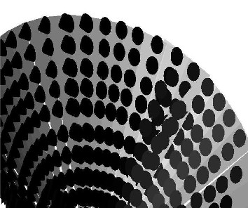
Fig 5. TWTA Phased Array (Top View)
A phased array antenna offers the possibility to steer the beam by means of electronic control. The antenna is composed of slotted waveguide radiators, high power precision phase shifters for elevation beam steering and electronics for driving and control of the phase shifters. The antenna beam may be electronically scanned in the vertical dimension to obtain altitude measurements of targets. The antenna features a very high gain narrow antenna beam with ultra-low sidelobes that are essential for the ability to send transmissions that can pierce the atmosphere’s worse weather conditions, any kind of jamming and uneven ground terrain. One may reduce the sidelobes in selected areas where interference is expected.
Costs have been significantly reduced through the
development of unique, highly affordable transmit/receive (T/R) modules featuring significantly fewer parts and electronic interconnects than other systems in competition. It also includes an open system architecture that readily accommodates growth via the insertion of future technologies. The ability to data link instructions from the Ground platform gives even greater effectiveness to this new automated tool. The programming of this can be done in a microcontroller installed in the EPCs.
Phase shift between adjacent sources:
Ψ = 2π (d/λ)sinθ (θ = angle of incidence)
A phase shift of Ψ is created between two EPCs emitting
microwaves. The shape and direction of pattern is determined by relative phases and amplitudes applied to each EPC.The array elements may be arranged in a volume. To avoid interaction with the feeding lines the polarization of the antenna elements has to be chosen orthogonal to these. This requires a careful design of the antenna
elements. With this constraint and some loss due to the feeding lines given, the volume array is the only configuration that has full hemispherical coverage with full use of all TR modules. This process is called beamforming[14].
To sum all signals coherently the time delay of the signal received at antenna element at position r= (x,y,z)T has to be compensated.
The path length difference between the element at position
r and the origins
rTω = xω + yω + zω= |r|.|ω| cosα (ωis the unit direction vector and α is the angle between r and ω)
With phase-only beam steering, the gain is approximately
equal to the number of elements, G≈ N. Thus to achieve high gain a large number of elements is needed. The beamforming operation by multiplying the signal with a suitable phase shift is therefore only correct for very narrowband signals. For broadband signals we have to apply at each antenna element the true time delays (TTD) Tk=rkT + ωo/c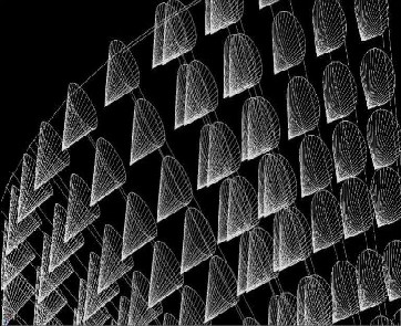
Fig 6. TWTA Phased Array (Bottom View)
IJSER © 2012 http://www.ijser.org
The research paper published by IJSER journal is about Solar Space Power Generation 6
ISSN 2229-5518
An operational amplifier ("op-amp") is a DC-coupled high- gain electronic voltage amplifier with a differential
input and, usually, a single-ended output. An op-amp produces an output voltage that is typically hundreds of thousands times larger than the voltage difference between its input terminals.
Fig 7. OP-AMP Circuit Diagram
The ground station is a very vital station as this is the station, which actually generates electricity. The objective of this station is to receive the beam of microwaves sent by the satellite and converting them back to electric current. The size of the receiver on the ground is a major hurdle, which needs to be crossed. This is achieved by a not so complex process. The ground station will be receiving the microwaves from the SPS at a rate of 1.2MW per beam of transmission every 0.502s. To receive 24 hour output, 2 different receiving stations have to be built each located diametrically opposite to the other to ensure that at least
one receiving station is within the line of sight of the
satellite.
This is because the transmitted beam comprises of microwaves generated by 5000 pairs of TWT Amplifiers, each with an output of 240 W per beam. To be able to convert large amount of power into electricity in such a short time period, the receiving station will consist of an array of rectennas. A rectenna[15] is a rectifying antenna,
which is used to convert the energy from an incoming
microwave beam into a Direct Current (DC) output. In a simple rectenna, the rectenna element consists of a dipole antenna with a diode connected across the elements of the dipole[16]. The diode rectifies the AC current induced in the antenna by the microwave beam, & gives a DC output. The working conversion efficiency of a rectenna is 90%, i.e. it converts 90% of the power received into a usable DC current.
To minimize power losses due to conduction &switching, the type of diode used is a Schottky Diode[17][18], which has a low forward voltage drop &a very fast switching action. A normal silicon diode has a drop of 0.6-1.7 V, while a Schottky Diode has a drop of 0.15-0.45 V. Since the area required for the collection of power from the SPS is quite large, it makes the usage of a single rectenna dish impractical, due to area considerations. To overcome this problem, we use an array of multiple smaller rectennas, which add up to give the same effective area as one
large dish.
For a solar array of area 10,000 m2
Solar Constant = 1361 W/m2
Area = 10,000 m2
Efficiency of Solar Cell = 29%
Therefore, power generated per second = 3946900W= 3.947
MW
For 1.98 MW transmission,
frequency of transmission = 0.502 seconds
Therefore, a beam will be transmitted every 0.502 seconds
No. of beams transmitted per day = 86400/0.502 = 172112
Total power received = 206534 MW = 206.534 GW per day
Total power generated = 206534.4x0.9= 185881MW=
185.881 GW per day.
Hardly any SPS program previously proposed has been able to produce energy on such a large scale. They also occupy a much larger area, as there is such area available in outer space. To increase the power output, we can increase the Solar Panel area and install more TWTs. Therefore, the system has much more scope for high amount of power generation compared to other such programs. Also due to the low weight and cost arrays, they have significant advantage over the recent 3J CPV system, which exhibited
IJSER © 2012 http://www.ijser.org
The research paper published by IJSER journal is about Solar Space Power Generation 7
ISSN 2229-5518
the highest efficiency but were highly bulky and expensive to use on a large scale.
3. ECONOMICS AND COSTS
Volume= 1.5 m3 (4 x 50m x 50m x 0.15mm) Volume of PDMS = 1.47 m3
Volume of Silicon =0.03 m3
Mass of PDMS = 1447.5 kg
Mass of Silicon = 69.87 kg (70 kg approx) Total Mass = 1517.5 kg
Cost of PDMS = $2/kg (Shanghai Qunyue Chemical Co. Ltd.) =>Total Cost of PDMS= $2895
Cost of Silicon = $0.17/100g => Total Cost of Silicon = $119
Total cost of cell = $3014
Launch Cost = $698,050
Mass of TWTs =4.4 kg
Total weight TWTs = 22000 kg
Taking a launch cost of $1000/lb., or $2205/kg which is achievable using ‚SpaceX’s ‘Falcon Heavy’ launch vehicle‛, we get a total mass of 23517.5 kg, which translates to a launch cost of $ 51,854,985 ($51.85 million).
Cost of 1 TWTA dual = $280,000 (Bosch Co. Ltd.) Cost of linearizer = $25000 (Bosch Co. Ltd.)
Total cost= $1,525,000,000($ 1.525 billion)
3.3 Solar Panels
Cost of Solar Array = $3014
3.4 Ground Station
Total Cost:$10.17 million (Each costing $2 and an array costing $30000 including wiring and structure)
$1.577 billion dollars
4. REFERENCES:
[1] 2012 The Outlook for Energy: A View to 2040 by ExxonMobil
[2] Current Carbon Dioxide Emission Higher Than It W as Just Before
Ancient Episode of Severe Global W arming Nature
GeoscienceScienceDaily (June 7, 2011)
[3] Evolvable Lunar Navigation and Communication Constellations
Kathryn Hamera and Todd Mosher
[4] The Lagrange Points – NASA website
(http://map.gsfc.nasa.gov/ContentMedia/lagrange.pdf)
[5] Hamera, K., Mosher, T., Gefreh, M., Paul, R., Slavkin, L. Trojan, J. “An Evolvable Lunar Communication and Navigation Constellation Concept,”, 2008 IEEE Aerospace Conference, Big Sky, MT, March 1-
8, 2008.
[6] Enhanced absorption and carrier collection in Si wire arrays for photovoltaic applications Michael D. Kelzenberg, Shannon W . Boettcher, Jan A. Petykiewicz, Daniel B.T. Evans, Morgan C. Putnam, Emily L. W arren, Joshua M. Spurgeon, Ryan M. Briggs, Nathan S. Lewis & Harry A. Atwater
[7] Photovoltaic Breakthroughs Brighten Outlook for Cheap Solar
Power- Scientific American
[8] Intuitive guide to communications All about Travelling W ave Tube
Amplifier Charen Langtn
[9] Travelling W ave Tube Amplifiers (TW TAs) for Space Applications Travelling W ave Tube Amplifiers from Bosch – for more than 4 million operating hours in space without failure.
[10]Teledyne MEC - W orlds Leading Helix TWT Developer & Manufacturer
[11] Hansen R. C., „Phased Array Antennas‟, W iley
[12] Aerospace System Improvements Enabled By Modern Phased Array Radar Northrop Grumman Electronic Systems Baltimore, Maryland October 2002 Robert Hendrix
[13] Fundamentals of Phased Arrays by Prabhu D. Patel ASTRON, The Netherlands Nov 2007
[14] Fundamentals of Signal Processing for Phased Array Radar Dr. Ulrich Nickel
[15] RECTENNA TECHNOLOGY PROGRAM by W illiam C. Brown
RAYTHEON CO.
[16] Princeton University Lecture Notes- Communications (16)
[17] Micro Note Series 401-Introduction to Schottky Rectifiers by Kent
W alters and Bob W erner
[18] Schottky Diodes by Rick Cory, Skyworks Solutions, Inc.
5. CREDITS
Graphics & Multimedia: Mr. Sahil N. Mathur(Current B.Tech CIC-Delhi
University) and Mr. Pawan Thukral
Scientific Details: Dr Vinod Chandra Senior Professor IIT Delhi
IJSER © 2012 http://www.ijser.org