International Journal of Scientific & Engineering Research, Volume 4, Issue 11, November-2013 1573
ISSN 2229-5518
Sliding Mode Control of a Doubly- fed Induction Generator(DFIG) for Wind Energy Conversion System
Mahmoud Zadehbagheri , Rahim Ildarabadi , Majid Baghaei Nejad
Abstract— The wind energy usage is one of the most important renewable energy with economic justification in the world. Due to the growing needs to the electrical energy, increased environmental pollutions and limitation in the fossils power resources, using of this energy in the power industry is necessary and inevitable. The broad use of wind Turbines in the power systems have caused that this Turbines have a decisive rule in these systems. So because of the better power quality of the Variable speed wind turbines, they are more applicable than the constant speed Turbines. Nowadays Speed control in doubly fed Induction Generator (DFIG) because of the advantages such as: good quality control, high efficiency, Improving power quality, no need to the capacitor banks and cost affectivity are used to have more. This paper presents a speed control of one doubly fed Induction Generator according to the sliding mode controller with the use of simulation in the MATLAB/Simulink environment and the simulation gained results demonstrate the ability of the proposed control strategy.
Index Terms— doubly fed induction generator (DFIG), W ind Farm, Variable speed wind turbine, Sliding mode control, power converter.
—————————— ——————————
1 INTRODUCTION
t the present time many countries are using of the wind energy as a constant energy. The installed capacity at the wind power is more than 25 GW worldwide. The wind
Turbines systems including of the wind Turbines with con- stant speed armed with one induction generator, variable speed armed with one squirrel cage induction generator and/or synchronous, variable speed with multi-pole perma- nent magnet synchronous generator and wind turbine with variable speed armed by Doubly fed induction generator (DFIG) which nowadays the most usage of the turbines in the wind farms are based on the Doubly fed induction generator for the reasons that they have some of the outstanding fea- tures such as the ability to produce different speed, the ability to control active and reactive power, improvement of power quality, reduce costs related to inverter, etc [1,2,3]. Variable speed in these turbines will make this ability in them that they can be in broader area of the winds and work in their maxi- mum efficiency. In this system will use of a wound-rotor in- duction generator that this wounded rotor connect to the net- work via the sliding rings to a converter machine and the sta- tor machine. One of the most important advantages of DFIG is that equipment of the power electronic is the only carrying a fraction of the total power around 20 to 30%, this means re- duction of losses and costs in the electronic power converter.

• Mahmoud Zadehbagheri is with the Hakim Sabzevari University, Faculty of Electrical Engineering, Sabzevar, Iran .(mahmood_zad@yahoo.com)
• Rahim Ildarabadi is with the Hakim Sabzevari University , Faculty of
Electrical Engineering, Sabzevar, Iran.( r.ildar@hsu.ac.ir).
• Majid Baghaei Nejad is with the Hakim Sabzevari University , Faculty of
Electrical Engineering, Sabzevar, Iran (mbnejad@hsu.ac.ir)
In addition to the providing necessary conditions for electrical network a wind system control zone has duty to provide pos- sible maximum transferring wind energy in the best efficiency, in this regard different controlling methods has been pro- posed by the researcher[4,5]. In this article for the control of the speed of Doubly Fed Induction Generator from a sliding mode control has been used. Sliding mode control theory is proposed by Utkin at 1977, after that theoretical works and its applications from the sliding mode control have been devel- oped. Since one of the most important benefits of sliding mode control is the “robustness” and this method is a nonlin- ear control method, so this will be used in the systems which there are uncertainty. This uncertainty may be structural (pa- rameters uncertainty) and/or non-structural, for example is not modelled dynamics. In this control method stability will be gained by holding of states of the system on the sliding base[5,6,7]. This paper offers a control method for inverter machine in order to regulate active and reactive power ’s been exchanged between machine and grid, in which the control of the active power is for the wind speed to be adapted in a wind energy inverter system and the control of the reactive power allows to reach a unity power factor between grid and stator.
2 OVERVIEW OF DOUBLY FED INDUCTION GENERATOR
The tremendous progress in the field of development of the wind turbines in order to power production has been started since 1975. The first modern turbine was connected to the grid around 1980. With development of usage of the wind energy and wind power production DFIG is using widely nowadays. The reason which this type of generator is calling as doubly fed induction generator is that, the produced electrical power transfers by two ways, stator as well as rotor. These generators are at the especial attention because of their features which
IJSER © 2013 http://www.ijser.org
International Journal of Scientific & Engineering Research, Volume 4, Issue 11, November-2013 1574
ISSN 2229-5518
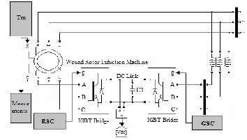
they have in the work with variable wind speed. The use of the wind power plants with variable speed has advantages in the compare with the wind power plants with constant speed. Although the wind power plants with constant speed are able to be connected to the grid directly, but wider energy range will be covered by wind power plants with variable speed, on the other hand they have lesser mechanical stress and lesser noise. Nowadays with development of the power electronics control of all the speeds is possible and cost effective[8,9]. This paper deals with DFIG with variable speed which has im- portant feature in the working with variable wind speed. As it has shown in the figure 1, the structure of a wind power plant designs in which the stator ’s orbit of DFIG connect directly and rotor ’s orbit of that connect by back to back converter (generator side converter and grid side converter) with slip- pery rings to the grid. Between two converters a capacitor that is calling as dc link are using as energy saver and to reduce voltage ripple[10,11].

Fig.1.A grid connected doubly-fed induction generator and its convertors
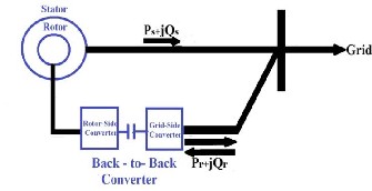
At the normal operation mode DFIG can control active and reactive power separately via grid side converter. Furthermore the rotor side converter can take away the need of the soft starter at the time of grid connection. Two subsystems known as mechanical and electrical systems are present that will show the overall control plane of the DFIG. The control sys- tems have been designed for different purposes, but the main goal is to control power to be injected to the grid[12].The ac- tive power released to the grid controlling by the rotor side converter, while injected reactive power controlling by both converter (figure 2).
Fig. 2.doubly fed induction generator
against overloading has been constructed. The mechanical subsystem for gag of the mechanical power output of the wind turbine by pitch adjustment has been designed. For the reason that, design of the low speed multipolar DFIG is not possible technically, for the DFIG base on the wind energy conversion systems gearboxes are still required. Use of the DFIG will make giving a good power factor to us possible even at the time which machine speed is out of the synchronous speed [12,13].
3 WIND GENERATION SYSTEM MODELING
3.1 MODELING OF THE DFIG
For the DFIG system modeling with variable wind speed the following is needed to be modeled: DFIG, turbine, the control unit as well as design a sliding mode controller which this paper will investigate all respectively. In the rotating field wound rotor induction machine model has shown in the fig- ure 3. [14].
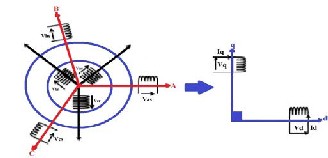
Fig. 3. Model of PARK of the DFIG
The equivalent circuit of a doubly fed induction machine with referring to the magnetic losses has shown in figure 4 and the mathematical machine model has been written in order to gaining of a decoupled system from control at a suitable refer- ence field (d-q) with a fixed stator flux. In this case the flowed active and reactive power control between DFIG stator and power grid with use of the sliding mode controller will be syn- thesized[15,16].
Fig. 4. equivalent circuit of DFIG
The electrical system also for the purpose of the protection
IJSER © 2013 http://www.ijser.org
International Journal of Scientific & Engineering Research, Volume 4, Issue 11, November-2013 1575
ISSN 2229-5518
DIFG classic electrical equation in the park field will be writ- ten as follow[4,17]: Stator and rotor voltage equations:
d
hand shaft speed of the generator be chosen in such a way at suitable speed area. Regardless of the transfer losses,
torque and shaft speed of the wind turbine which is related
Vds =

d Φ ds − ωs Φ qs + rs ids
to the gearbox side is given by the below equation:
V = dt Φ
+ ω Φ
+ r i
(1)

Vqs = d Φ qs − ( s
ds ) s qs + T

dr ddt dr
ωs − ω
Φ qr
rr idr
Tm =
And
Ω mec
= G.ωt
(8)

Vqr = Φ qr + (ωs − ω
dt
)Φ dr + rr iqr G
the flux equations for stator and rotor are such as:
Φ qs = (Lls + Lm )iqs + Lm iqr


which in that is torque of the generator and is as
Φ ds = (Lls + Lm )ids + Lm idr
Φ qr = (Llr + Lm )iqr + Lm iqs
Φ dr = (Llr + Lm )idr + Lm ids
(2)

wind turbine’s mechanical speed. The wind turbine is able to produce a certain amount of the power proportional with wind speed. This amount which is expressing by is
Torque generated of DFIM Based on stator currents and rotor flux is shown as follows:
a function of wind speed and also it is a function of Pitch
angle blades of the wind turbine[4,18]. Although this equa-


T = 3 P Lm (Φ i
− Φ i )
(3)


tions looking simple, is depends on the relation that is
e 2 L
dr qs
qr ds

actually between turbine’s angular velocity and wind
here P is the number of pairs of the poles. Mechanical dynamic equation is expressed as follows:
dwm
speed V. this ratio is known as tip speed ratio and is such as:
ω

J + Bwm = Te − TL
d t
(4)

λ = t .R V
(9)
Here J and B are Moment of machine inertia and friction


The relation between and is shown in the figure 5, as it is
coefficient respectively. TL
is the external load torque and
clear some of the there is a return to that will be maxi-
mum and this factor causes maximum of the power for the
ωm is the rotor’s mechanical speed.
The total active and reactive power production is as follow:
given wind speed.
P = Vds ids + Vqs iqs + Vdr idr + Vqr iqr
Q = Vqs ids − Vds iqs + Vqr idr − Vdr iqr
(5)
3.2 MODELING OF THE WIND TURBINE AND GEARBOX

Wind Energy Conversion Systems (WECS) are the sets which are using to conversion of the wind energy to mechanical en- ergy. The amount of capacity which is receivable as by wind turbine has direct proportion with power coefficient
and also its relationship is as follow:

P = 1 C
t 2 p
(λ, β ).r
air
.R 2 .V 3
(6)
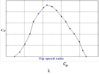
Fig. 5. Aerodynamic power coefficient variation against tip speed ratio
The
r air
is air density, R is expressed as Blade radius, V
consists of air speed, and B is angel of the blade’s turbine.
The power coefficient curve
C p (λ, β ) for a given speed
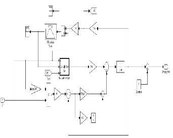
Figure 6 is showing the simulated overall schematic for the

will be expressed base on the λ . The turbine torque is the ratio of output power to shaft speed and is equal to:
wind turbine, gearbox and shaft.

T = Pt
(7)
t
t
The turbine normally connects to the shaft generator by gearbox that the ratio of its gear is equal to G, on the other
IJSER © 2013 http://www.ijser.org
International Journal of Scientific & Engineering Research, Volume 4, Issue 11, November-2013 1576
ISSN 2229-5518
induction generator. Converter controls will be modeled base on the rotor controlled voltage source, so in the space of two axial d and q the amount of the rotor ’s d and q axial voltage should be clear.
4.1.2 Grid Side Converter (GSC) control
Since DFIG base on the wind system is sensitive to the voltage changes, disturbed grid voltage conditions should be consid- ered in the quality design of GSC. As noted the most im-
portant task of grid side converter is regulate bus voltage re-
gardless of the rotor power flow side, so Vdc
should be com-
Fig. 6. simulated overall schematic for the wind turbine, gearbox and shaft.
4 WIND TURBINE CONTROL BY DFIG
Control of the fixed output DFIG idea is for stator; such as three phase voltage, frequency and output power function that feed network via stator current. Control of the machine is by converter; moreover output active power can be controlled by slope of turbine blades which it is adjusting on the β angel blade. In other words, coefficient of aerodynamic efficiency changes the rotor ’s blade angel. If the wind speed exceeds the rated value, this angel control is used for output power fixa- tion. The wind turbine with doubly fed induction generator are include two main controls which are involve back to back converter and vane angel control, which we will investigate any each of them[19,20].
4.1 Back to Back Converter Control
The back to back converter is including of four main parts: including of two inverters, that each of them besides switching control have another control as well, which rotor side convert- er is responsible for voltage control or reactive power and ex- traction of the optimal power from the wind, network side converter is responsible for control of the DC bus voltage amount, DC which is interface of the two converter and trans- former or series reactors which connects the converter to the network.
4.1.1 Rotor Side Converter (RSC) control
The main task of this converter is output power control and terminal voltage of the DFIG. In this method the rotor side converter is similar to common methods use in the doubly fed
pared with its reference amount and applies to a PI controller to take the amount of the flow at the grid side converter. Con- trol of the GSC by use of the merged Sliding mode controller (SMC) and PI controller under grid disturbances for the dy- namical control performance evaluation of DFIG has been done in this paper.
4.2 Vane angle Control
According to the  -
- curve shown in figure 5, in order to maximum power extraction of the wind, zero helix angels should always be considered unless the rotor speed is greater than the allowable. So, for the control of vane angel only the velocity difference between the maximum speeds should ap- ply to a PI controller and area of changes can be limited be- tween zero and maximum angel. Also it should be noted, speed changes of the vane angel should not be more than a clear amount.
5 DESIGN OF SLIDING MODE CONTROL ALGORITHM
The sliding mode control is a nonlinear control method which guarantees the control strategy in the face of uncertainty. In this case the system stability is obtained by keeping the sys- tem’s states on the sliding surface. The sliding mode controller is a variable structure controller which switches with high- frequency between several control rules. Basically, the variable structure controller is including of several different continues environs that can map plant state to a control surface, while switching between different environs by shown plant state is determined by a function switching Controller implements a nonlinear control rule in order to drive and keep the state of the system on a favourable hyper surface. A special issue about control plan is that define a sliding surface with proper- ty guaranteed of stability and attractiveness[21]. The sliding mode method has high flexibility, also it is effective and very strong method (quite robust), and on the other hand it needs relatively less information about the system and also is insen- sitive to the parametrical changes of the system. The sliding
IJSER © 2013 http://www.ijser.org
International Journal of Scientific & Engineering Research, Volume 4, Issue 11, November-2013 1577
ISSN 2229-5518
mode controller doesn’t need to the mathematical models ac- curately like classical controllers but needs to know the range
V qr = Vqreq − Vqrn ,V dr
= Vdreq − Vdrn
(14)
of parameter changes for ensuring sustainability and condi- tion satisfactory [22]. The block diagram of the SMC in a vari- able speed wind turbine application in this paper is shown in Figre. 7
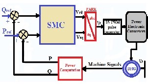
Fig.7. Block diagram of a sliding mode control of a DFIG.
The sliding mode control method is including of the compe- tent of the calculation of equivalent and discontinuous varia- ble control from a favourable surface of the selected sliding mode[23,24].
where n shows discrete components of the rotor voltage of
reference. The designed control unit has shown by
MATLAB/Simulink software at the below figure.
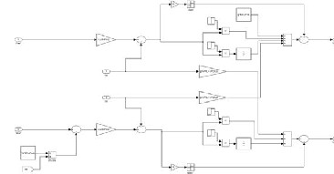
Fig. 8. Diagram of the control strategy
A simple form of control operation is a relay function by slid- ing mode theory. Design of the control unit is expressed by use of equation (15) which in that we see fusion of sliding control
∗∗ ∗ ∗
S• (φdr ) = φ• dr − φ•dr , S•(φqr ) = φ• qr − φ•qr
(10)
unites and PI.
s(φdr ) = φ
dr − φ dr , s(φqr ) = φ
qr − φ qr
U dq
= U PI
+ K ∗ sign(S dq )
(15)
Reference fluxesφqr ,φ dr
will be defined in accordance with
the objectives control of stator current. In the sliding mode
regimen of the system dynamic in the sliding mode is subject-
6 SIMULATION RESULTS AND DISCUSSION
ing to the following con•ditions:
S (φ ) = 0
and we have for
To verify the proposed method, simulation results of a DFIG
the ideal sliding mode:
S (φ ) = 0
generator sample has shown by MATLAB /Simulink software
Reference stator voltage components in order to sliding mode conditions define as follow:
∗
in this section. In this section the performance of the DFIG
system is analysed under grid voltage fluctuations. The wind
turbine is of doubly fed induction generator type. The sliding
Vdreq
= φ dr +
∗
1 ∗

dr
1Tr
− W φ ∗ rq

− 1 l i ∗
1Tr
(11)
mode controller has been achieved base on the stator flux ori- entation reference in order to control of the active and reactive
Vqreq = φ
qr +

φ qr + Wrφ
Tr
∗ dr −

l i∗ qs
Tr
powers by direct component and stator flows second degree and via desired power flow between grid and generator in the
Vdreq
and Vqreq
are component of the rotor voltage respec-
tively. The stator currents sliding surface will be calculated
based on the below equations:
∗ ∗
S (ids ) = i ds − ids , S (iqs ) = i qs − iqs
(12)
The reference rotor flux in the sliding mode regimen is deter- mined by below equation:
φ ∗ dr

= slr
rs

ds
∗ − W i ∗ sq

− 1 u −
rs ∗

qs
(13)
Wssllm s r
s r sws
φ ∗ qr
= r (− s i
∗ − W i ∗ ds − s i ∗ )
Ws lm s
sws
where s is the to2tal leaking constant and determines as be-
low:

s = l (1 − l m )
MATLAB environment (figure.9).
ls lr
Fig.9. configuration of wind turbine and DFIG system with MATLAB
Rotor voltage of references defines as follow:
IJSER © 2013 http://www.ijser.org
International Journal of Scientific & Engineering Research, Volume 4, Issue 11, November-2013 1578
ISSN 2229-5518
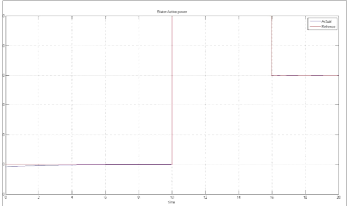
Fig.10. stator active power
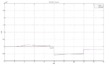
Figure 10,It is about stator active power along with amount of reference(favourable) and real amount which, as it has shown in the figure, real amount and reference amount convergent to each other very fast.
Fig.11. stator reactive power
Figure 11, As it has shown it is related to the stator reactive power along with reference amount as well as the real amount which this amount convergent very fast to the reference amount.
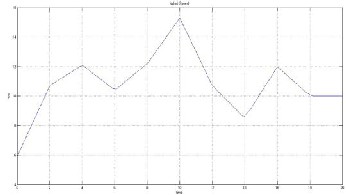
Fig.12. variable speed of wind Turbine
Figure 12, It is related to variable speed according to the time
related to the wind turbine.
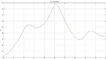
Fig.13. shaft speed of wind Turbine
Figure 13, The speed of the turbine shaft has been demonstrat- ed which this speed is proportional with wind speed.
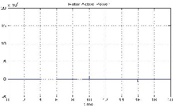
Fig.14.Active power of Rotor
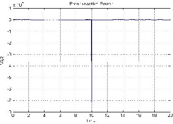
Fig.15. Reactive power of Rotor
IJSER © 2013 http://www.ijser.org
International Journal of Scientific & Engineering Research, Volume 4, Issue 11, November-2013 1579
ISSN 2229-5518
d-q reference frame,
I ds , I qs , I dr , I qr
Stator and rotor current components in the
Figure 14, 15: these figures are related to active and reactive
powers of rotor but these are unwanted powers and much less can be better.
d-q reference frame,
Φ ds , Φ qs , Φ dr , Φ qr
d-q reference frame,
ωs , ωr
Stator and rotor flux components in the
Stator , Rotor Pulsation,
Tm , Te tively, Ls , Lr
Lm
rs , rr
TL
ωm
Mechanical and electromagnetic torques respec-
Stator and rotor inductances, Magnetizing inductance Stator and rotor resistances, External load torque
Rotor mechanical speed
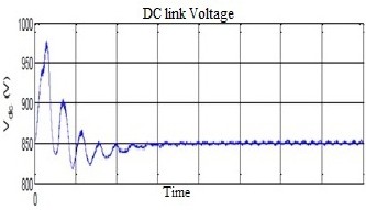
Fig.16. DC link Voltage under balanced grid
7 CONCLUSION
In this paper a complete system for electrical energy produc- tion by use of the doubly fed induction generator (DFIG) has been done via wind turbine. The studied system has been formed of a DFIG with stator and rotor, which in that stator has connected to the grid directly and rotor has connected to the grid via two converter, machine converter and grid con- verter. Control of the machine inverter provides at the first a set of active and reactive powers exchanged between the grid and the machine. With the consideration of turbine variable velocity state and design controller for DFIG in form of using of the sliding mode, we have reached to the favourable results
in spite of the uncertain system active and reactive powers.
P, Q active and reactive grid powers
s total leaking constant
APPENDIX: PARAMETERS
Paeor
Tt
NOMENCLATURES
The wind available power, Wind turbine torque (Nm),
V Wind speed (m/s),
R Blade radius (m),
rair
Air density,
β Pitch angle,
Ρ Number of pole pairs,
C p ωt Ωmec
Power coefficient,
Wind turbine angular speed (shaft speed) (rad/s),
Wind turbine Mechanical speed (rad/s) ,
λ Tip speed to wind speed ratio of the Wind Turbine,
G Mechanical speed multiplier (gearbox) ,
J Moment of inertia,
B Coefficient of viscous friction,
Vds , Vqs , Vdr , Vqr
Stator and rotor voltage components in the
IJSER © 2013 http://www.ijser.org
International Journal of Scientific & Engineering Research, Volume 4, Issue 11, November-2013 1580
ISSN 2229-5518
REFERENCES
[1] Harini. C, Kumari. NK, Raju. GS, "Analysis of wind
turbine driven doubly fed induction generator", in International
Conference on Electrical Energy Systems (ICEES), pp.246-251,
[2] Chen. WL, Hsu, "Controller Design for an Induction
Generator Driven by a Variable-Speed Wind Turbine", IEEE
Transactions on Energy Conversion, Vol. 21. No. 3, pp.625–635,
2006.
[3] F. Poitiers, T. Bouaouiche, M. Machmoum “Advanced control
of a doubly-fed induction generator for wind energy conversion”
Electric Power Systems Research 79 (2009) 1085–1096
[4] Kh. Belgacem1, A. Mezouar1, A. Massoum , " Sliding Mode Control of a Doubly-fed Induction Generator for Wind Energy Conversion ", International Journal of Energy Engineering 2013,
3(1): 30-36 DOI: 10.5923/ j.ijee.20130301.05.
[5] VI. Utkin, Variable structure systems with sliding modesa
survey. IEEE Trans. Automat Control,; Vol. 22, N°. 2, pp. 212-222,
1977.
[6] H. Amimeur, D. Aouzellag, R. Abdessemed, K.
Ghedamsi, Sliding mode control of a dual-stator
induction generator for wind energy conversion systems,
Electrical Power and Energy Systems, Vol. 42, pp. 60-70,
2012.
[7] Youcef Bekakra, Djilani Ben Attous " Comparison Study be-
tween SVM and PWM Inverter in Sliding Mode Control of Active
and Reactive Power Control of a DFIG for Variable Speed Wind
Energy ", INTERNATIONAL JOURNAL of RENEWABLE ENER-
GY RESEARCH ., Vol.2, No.3, 2012
[8] Gautam. D, Vittal. V, Harbour. T, "Impact of Increased
Penetration of DFIG-Based Wind Turbine Generators on
Transient and Small Signal Stability of Power Systems", IEEE
Transactions on Energy Society, Vol. 24. No. 3, pp.1426-1434,
2009.
[9] G. Tapia, A. Tapia, and J.X. Ostolaza, "Modeling and control of wind turbine driven by doubly fed induction
generator", IEEE Trans. Energy Conversion, Vol.18, No.2, pp.194-204, Nov. 2004.
[10] Yanhua. L, Zhang. Xu, Zhao, Dongmei. M, "Research on the Wind Farm Reactive Power Compensation Capacity and Control Target", in Asia Pacific Power and Energy Engineering Conference (APPEEC), pp.1-5, 2011.
[11] Adria Junyent-Ferre, Oriol Gomis-Bellmunt , Andreas Sumper, Marc Sala, Montserrat Mata , "Modeling and control of the doubly fed induction generator wind turbine ",Simulation Modelling Practice and Theory 18 (2010) 1365–1381, Elsevier.
[12] H.T. Jadhav, Ranjit Roy, A comprehensive review on the grid integration of doubly fed induction generator. Electrical Power and Energy Systems.49(2013)8-18
[13] Huazhang H, Chung CY. “Coordinated damping control de- sign for DFIG-based wind generation considering power output variation”. IEEE Trans Power Syst 2012;27(4):1916–25.
[14] B.hamane, M. benghanem, A.M.bouzid, A.belabbes, “Control for Variable Speed Wind Turbine Driving a Doubly Fed Induction Generator using Fuzzy-PI Control” Energy Procedia Published by Elsevier Ltd, 18 ( 2012 ) 476 – 485
[15] J. G. Slottweg, S. W. H. Haan, H. Polinder, and W. L. Kling, "General Model for Representing Variable Speed Wind Turbines In Power Systems, " Vol.18,No.1,2003, pp.144151,2003.
[16] A. Han, Z. Zhang, and X. Yin, "Study of Factors Affected the Rotor Over-Current of DFIG During The Three Phase Voltage Dip," IEEE, Third Int. Conf. on Elect. Utility
[17] Yerra Sreenivasa Rao , A. Jaya Laxmi"
Direct torque control of DFIG based wind turbine under voltage
dips"international journal in advance in engeeniring,may2012
[18] A. Gaillard, P. Poure, S. Saadate, M. Machmoum “Variable
Speed DFIG Wind Ener gy System for Power Generation and
Harmonic Current Mitigation, Renewable Ener gy 34,2009,
pp 1545-1553
[19] o-ming yin, gengyan li, ming zhou, “Study on the control of
DFIG and it’s Responses to grid disturbances” IEEE 2006.
[20] Yazhou Lei, Alan Mullane, Gordon Lightbody and Robert
Yacamini,”Modeling of the Wind turbine with a
doubly fed induction Generator for grid integration studis” IEEE
transactions on energy conversion, Vol.21.NO1, March 2006
[21] I. Munteanu, A. I. Bratcu, N.-A. Cutululis, and E. Ceanga,
Optimal Control of Wind Energy Systems: Towards a Global Ap-
proach, 1st ed. Springer, March 2008, iSBN-13: 978-1848000797.
[22] A. J. Pujante-L opez, E. Gomez-L azaro, A. Molina-Garcia, J.
A. Fuentes-Moreno and S. Mart in-Martinez” State of the Art of
Wind Turbines Modelling with Induction Generator (DFIG)"
[23] M.O. Mahmoudi, N. Madani, M.F. Benkhoris ″Cascade slid-
ing mode control of a field oriented induction machine drive″,
Eur. Phys, AP 7, 1999, pp.217-225.
[24] Abdelhakim Dendouga ,Rachid Abdessemed ,M. Loukmene
Bendaas, Azzeddine Chaiba" Sliding mode control of active and
Reactive Powers generated by a doubly-fed Induction Generator
Damascus University Journal Vol. (24)- No. (2) 2008 Dendouga -
Abdessemed Bendaas-Chaiba
BIBLIOGRAPHY OF AUTHORS

Mahmoud Zadehbagheri was born in Ya- souj, Iran in October 1979. In 2003 he re- ceived his B.S. in Electrical Engineering from Kashan University and in 2008 he received his M.S. in Electrical Engineering from the Islamic Azad University, Najafa- bad Branch,he is currently pursuing your PhD at Hakim sabzevari university. He is with the faculty of the Electrical Engineer-
ing Department, Islamic Azad University of yasouj. His research interests includes the fields of power electronics,electrical machines, drives and controls.

Rahim Ildarabadi was born in Sabzevar, Iran in 1975. He received the PhD degree from Ferdowsi University of Mashhad in
2010. He is a full time faculty member at Sabzevar Hkim Sabzevari University. His main area of interest are automation sys- tem, electrical machine derive, renewable energy, instruments and measurement. He is currently an Assistant Professor of elec-
trical engineering at Hakim SabzevariUniversity.
IJSER © 2013 http://www.ijser.org
International Journal of Scientific & Engineering Research, Volume 4, Issue 11, November-2013 1581

ISSN 2229-5518
Majid Baghaei Nejad received the B.S. and M.Sc degree in electrical engineering from Ferdowsi University, and Tarbiat Modares University, Iran, in 1996 and 2000 respectively, and his PhD degree in electronic and comput- er systems from Royal Institute of Technology (KTH), Stockholm, Sweden in 2008. Since 2000 he has been with electronics department at Hakim Sabzevari University, Iran, where cur- rently has an assistance professor position.
His current research work includes low power analog/RF integrated cir- cuit design, ultra wideband communication, RFID systems and wireless sensing.
IJSER © 2013 http://www.ijser.org