International Journal of Scientific & Engineering Research, Volume 6, Issue 4, April-2015
ISSN 2229-5518
1710
Rheological Study of Fillers used in PVC Plastisol for Industrial Applications
aBhasha,aParul Malik, aPurnima Jain and bAbhijit Baruah
aNetaji Subhash Institue of Technology, Dwarka Sec-3,University of Delhi,INDIA
bHenkel Teroson India Ltd Gurgaon, INDIA
Author’s email- sharmabhasha@gmail.com
Abstract - Rheological tests (Study of flow) are used widely to evaluate functional coatings in terms of their properties and performance Fillers have long been recognized as useful additives for thermoplastics and particularly in PVC for many applications due to its low cost and good mechanical
properties. Ground calcium carbonate is generally used as filler with an interesting ratio performance and price; it improves physical properties, Impact
strength (Particularly at low temperature). In this paper,we are concerned with the rheological properties of effect of fillers of different grades prepared with plastisizer DOP-Dioctylerepthalate (1:1 ratio)by using Stirrer.Flow behaviour is characterized by using different panels which are used in automobile applications viscosity is measured by using BF-Viscometer,spindle#7 ,study of matuaration time of fillers by using cone and plate Shear
rheometer by Anton Paar and study of srtructure recovery of fillers using Three Interval Thixotropy Test (3IT). Thus,conclusion can be drawn that The
viscosity of thixotropic materials does not follow the same path on structure breakdown and recovery. If modulus is high which is calculated by slope
,material is highly rigid ,it means less flexible like WSPT is very less flexible , but there will be the chances of gel formation, hence CCR 501 will be the best filler,it can be used according to the automotive applications. For PVC, the material whose viscosity is decreasing when high shear rate is applied is preferred like UBC (Under Body Coating) in automotive applications. A better understanding of the factors affecting the behavior of Plastisol will go a long way in changing the art of Plastisol formulation to a science.
Index Terms - Fillers,Calcium Carbonate, PVC plastisol,DOP, Viscosity, Rheometer, 3IT
—————————— ——————————
1. INTRODUCTION
Rheology is a study of the change in form and flow of matter, embracing elasticity, viscosity, and plasticity. Rheology, the
most sensitive method for material characterization because flow behavior is responsive to properties such as molecular weight and molecular weight distribution. Rheological measurements allow the study of chemical, mechanical, and thermal treatments, the effects of additives, or the course of a
controlling factor.
Under these circumstances this parameter is a function of shape, morphology and the particle size distribution, but not necessarily of size itself. Typical inorganic and organic fillers used in polymers (i.e., plastics), etc., are: bestos, Carbon black, Alumina, Titanium Dioxide, Zinc Oxide, Calcium
2
curing reaction1. Fillers are added to polymer melts in order
Carbonate,quartz, clays, glass fibres etc
.As Calcium
to—among many other things— reduce the cost of, or increase the stiffness of the resultant solid polymer articles. On the other hand, polymer binders and thickeners are often added to aqueous dispersions of functional dispersed particulate material to improve the physical stability and aesthetic appearance. The filler particles that we are interested in here can often be considered to be large enough—super-micron—to neglect Brownian motion, so that generally the effective phase volume relative to the maximum phase volume is the primary
————————————————
Bhasha is currently pursuing PhD in Chemistry in Netaji Subhas Institute of Technology,University of Delhi, India, E-mail: sharmabhasha@gmail.com
carbonate has long been recognized as useful additives for
thermoplastics and particularly in PVC for many applications. Ground calcium carbonate is generally used as filler with an interesting ratio performance/price. Precipitated Calcium Carbonate (PCC) however exhibits a much smaller particle size. The specific structure and granulometry of PC allows these materials to fulfil additional functions like Processing aid, impact modification and better weatherability3. PVC Plastisol is dispersion of a polyvinyl chloride polymer in a plasticizer. The PVC is generally a 95 percent PVC/5 percent vinyl acetate copolymer. The vinyl acetate is included as an internal plasticizer for the resin. Phthalates such as DOP (dioctyl phthalate) and DINP (diisononyl phthalate) are typically the plasticizers used4. PVC (polyvinyl chloride) Plastisol sealants are among the highest volume sealants used
IJSER © 2015 http://www.ijser.org
International Journal of Scientific & Engineering Research, Volume 6, Issue 4, April-2015
ISSN 2229-5518
1711

in the manufacture of automobiles, trucks, and buses.
Plasticisers make the hard PVC resin softer. Primary plasticizers have good compatibility with PVC resin and can be absorbed in large quantities. In special cases as much as 140-150
PHR of Primary plasticiser can be gelated into PVC for super soft products. Nearly all Plasticisers are liquids and have to be absorbed in Suspension resin in heated mixers. High Speed mixers (which generate frictional heat while mixing) are the most popular types of dry blending equipment5. Heated Ribbon blenders and Sigma mixers are only used when very high Plasticiser levels are required. There is a vast array of Primary plasticizers for PVC. This discussion will be limited to the most popular, the Phthalate Esters. Phthalic acid is reacted with various alchohols to manufacture a family of Phthalate plasticizers of which Di Octyl Phthalate (DOP) is the most popular. An individual vehicle incorporates PVC Plastisol in many places, but the uses generally fall into three categories: sealing the body against entry of wind, rain, dust and noise; improving the quality of the car and ride by deadening sound as well as reducing hood flutter; and protecting against corrosion with underbody coatings.6 For body sealing, Plastisol fill joints and seams between body panels, on the floor pan, where the drip rail meets the roof, at center pillar seams, at welded joints, joints at door corners, and in the trunk. They are also used to seal joints in various subassemblies such as the wheelhouse. The other significant use for PVC Plastisol sealants outside automotive is airport runway and highway joint filling and crack sealing7-8. Plastisols are single-component adhesives that are applied as a paste to the substrate. The paste consists of solid polyvinylchloride (PVC) particles dispersed in plasticizer. In order to form a bond, the applied adhesive is heated so that the thermoplastic PVC swells and Plastisols have high flexibility and good peel resistance.
2. EXPERIMENTAL
The properties of these filler systems that determine their particular contribution to the viscous and non-linear viscoelastic properties of the polymeric systems that they are added to, include there9:
Chemical Composition
Color Morphology Hardness Particle Size Specific Gravity.
2.1 Types Of Fillers
1. CCR 501- Fatty acid coated, Average particle size 0.06 micron, Hexagonal crystallite. It used as reinforcing agent & PVC products; its heat stability and dispersability are
excellent. It also improves scratch resistance, brightness,
gloss, cold resistance and reduces the whitening on flexure.
2. Neolight SP (NSP) - Fatty acid coated, Particle Size
(micron) 0.08 (Typical), BET Surface Area 13 - 19 m²/g, Viscosity control in various kinds of Sealant ,Thixotropic in PVC Plastisol, Smooth finish and high gloss in PVC compound.
3. Visco 30- Rhombohedral crystallite. Average particle size
0.03 micron, BET Surface Area 32 m²/g, No information about coating.
4. VISCOLITE OS- Coated, Particle Size (micron) 0.08 and
cubic crystallite, BET Surface Area 17 m²/g, Thixotropic in
PVC Plastisol excellent anti sag and anti slip properties
5. WSPT- coated 0.4 % moisture content, BET surface area
20.54 m²/g.
Five Samples of fillers were prepared by using DOP plasticizer
(1:1 ratio) by using stirred at room temperature.
2.2 BF Viscometer (Brookfield)
Spindle #7 on 5 rpm at 30°C is used to measure viscosity of given samples. All Brookfield laboratory viscometers are accurate within +/-1.0% of the measurement range in use and have repeatability with +/-0.2%. For on-line viscosity measurement and control, Brookfield rotational viscometers provide accurate and repeatable data10.
2.3 Rheometer
There are two distinctively different types of rheometers.
1. Rheometers that control the applied shear stress or shear strain are called rotational or shear rheometers, whereas
2. Rheometers that apply extensional stress or extensional strain are extensional rheometers.
Types of shear Rheometers:-
1. Pipe or Capillary 2. Rotational Cylinder 3. Cone and plate
Here, Cone and Plate is used.
Cone and Plate Rheometer 11 ( Standard Used: - JASO
Instrument used: - Rheo Lab QC Maker: - Anton paar )is used to measure the way in which a liquid, suspension or slurry flows in response to applied forces. It is used for those fluids which cannot be defined by a single value of viscosity and therefore require more parameters to be set and measured than is the case for a viscometer. It measures the Rheology of the fluid.Rheological aspects of these samples after sampling, after
24 hrs and after 48 hrs using above Rotational Rheometers like viscosity, yield value, shear viscosity etc are studied.
2.4 The 3-interval thixotropic test 3IT provides the application-specific assessment of a coating within a few minutes. Moreover, application specialists can utilize the progress of the viscosity function over time to determine the
IJSER © 2015 http://www.ijser.org
International Journal of Scientific & Engineering Research, Volume 6, Issue 4, April-2015
ISSN 2229-5518
1712
thixotropic behavior of a sample. The test procedure
reproduces the application process through the following three measuring intervals:
Rest: Assessment of the structure at rest as the initial state prior
to the processing step. High shearing: Assessment of the structural decomposition behavior during application. Rest: Assessment of the structural regeneration with respect to time after application, thus enabling the determination of the surface leveling and sagging behavior. The rapid structural regeneration showed by Sample A demonstrated inadequate leveling but less sagging. The slow structural regeneration showed by Sample B demonstrated its better leveling behavior. However, Sample B will produce an inadequate layer thickness owing to its strong tendency to sag. Moreover, the structural regeneration and drying behavior affect the fixing and leveling of pigments used.
3. RESULTS & DISCUSSIONS
Table 3.2.1 WSPT has high viscosity at room temperature, therefore chances of sag of material is low when
applied in automotive applications depending upon the chances of gel formation.
3.3 Study of Maturation Time of Various Fillers Used In PVC Plastisol
3.1 Flow Behaviour of Fillers/ Sag Resistance Test

300
Pa
260
240
220
Rheoplus
100
Pa ·s

300
Pa
260
240
220
200
Rheoplus
100
Pa ·s
200
180
CCR 1 1
180

160

10
CCR 501:DOP 1
CC17-SN3382; d=0 m m

Shear Stres s
 160
160
 140
140
120


10
CC17-SN3382; d=0 m m

Shear Stres s
Vis cos ity
140
120
100
80

Vis cos ity
100
80
60
40
20
0

1
0 20 40 60 80 100 1/s 120

.
She a r Ra te
60
40
20

0 1
0 20 40 60 80 100 1/s 120

.
She a r Ra te
Anton Paar GmbH
Anton Paar GmbH
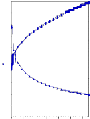
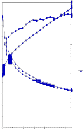
Viscosity = 640 | 1200 |
Yield Value = 127.73 | 92.55 |
Shear Viscosity = 1.27 | 1.57 |
Fig 3.3.1 CCR 501- After Sampling & After 48 hrs
Table 3.1.1 Test on different panels after Sampling of fillers kept at angle of 90°
Table 3.1.1 Test on different panels after baking at
140°C for 30 min kept at angle of 90°
3.2 Viscosity Test by BF Viscometer on Spindle-7 on
5 r.p.m at 30°C
IJSER © 2015 http://www.ijser.org
International Journal of Scientific & Engineering Research, Volume 6, Issue 4, April-2015
ISSN 2229-5518
1713
500

Rheoplus
1,000
500
Rheoplus
1,000

400
Rheoplus
1,000
Pa
450
400
350
300
250
200
150
Pa·s
100


10
NSP 1278
CC17-SN3382; d=0 m m

Shear Stres s
Vis cos ity
Pa
450
400
350
300

250

200
150
Pa·s
100


10
NSP:DOP 2
CC17-SN3382; d=0 m m

Shear Stres s
Vis cos ity
Pa
350
300
250
200
150
Pa·s
100


10
CCR 501:NSP 1
CC17-SN3382; d=0 mm

Shear Stress
Viscosity
1,000
Pa
900
800
700
600

500

400
Rheoplus
1,000
Pa·s
100


10
VISCOLITE 0S 48 HRS 1 Bingham I 2
tau0 = 565.65 Pa; eta_inf = 2.6886 Pa·s

Shear Stres s
Vis cos ity
100
100
100
300
50 50
200
50
0 1
0 20 40 60 80 100 1/s 120

.
Shear Rate
Anton Paar GmbH


0 1
0 20 40 60 80 100 1/s 120

.
Shear Rate

Anton Paar GmbH
0 1
0 20 40 60 80 100 1/s 120

.
Shear Rate
Anton Paar GmbH
100

0

1
0 20 40 60 80 100 1/s 120

.
Shear Rate
Anton Paar GmbH
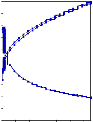
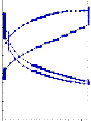
Viscosity = 2240 2560
Yield Value = 291.87 277.57
Shear Viscosity = 1.73 1.80
Fig 3.3.2 NSP- After Sampling & After 48 hrs
2.68
Rheoplus

Rheoplus
Shear Viscosity = 2.76 2.68
3.3.5 Viscolite- OS- After Sampling & After 48 hrs
Here. If we keep these samples for storage then WSPT will
1,300
Pa
1,200
1,100
1,000
Pa·s
1,100
Pa
1,000
900
1,000
Pa·s
convert into gel because viscosite is increases day by day. Hence in industrial applications, According to this test CCR 501
1,000
900
800  700
700
100

VISCO 30 2
CC17-SN3382; d=0 m m

Shear Stres s
800
700  600
600

100
VISCO 30:DOP 2
CC17-SN3382; d=0 mm

Shear Stress
is used, also because of low cost but there will be chances of sag if applied at high temperature.

600

Vis cos ity
500
Viscosity
500
400
300
200
100
0
10
1
0 20 40 60 80 100 1/s 120

.
Shear Rate
400
300
200
100

0
10

1
0 20 40 60 80 100 1/s 120

.
Shear Rate
3.4 Shear Stress vs Shear Rate Graph by using Data
Points obtained by Rheometer
Anton Paar GmbH
Anton Paar GmbH
By the above results,we have taken a 50:50 ratio of CCR 501 &
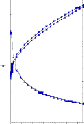
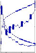
Viscosity = 4240 5440
Yield Value = 482.51 627.92
Neolite SP with DOP plasticizer with the above samples to plot a graph between Shear Stress vs Shear Rate because they both have low viscosity.
Shear Viscosity = 5.56 3.32
3500
Fillers After Sampling
CCR 501
NSP
3000
VISCO 30
Fig 3.3.3 Visco-30 – After Sampling & After 48 hrs
2500
2000
W SPT
CCR
501/NSP
Viscolite OS
1500

3,000
Pa
2,600
2,400
2,200
2,000
1,800  1,600
1,600
Rheoplus
1,000
Pa·s
100

10
WSPT 1
CC17-SN3382; d=0 m m

Shear Stres s
3,000
Pa
2,600
2,400
2,200
2,000
1,800  1,600
1,600
Rheoplus
1,000
Pa·s

100
WSPT 3
CC17-SN3382; d=0 m m

Shear Stres s
1000
500
0
0 20 40 60 80 100 120 140
Shear Rate, per sec

1,400
1,200
1,000
800
600
400


Vis cos ity
1
1,400
1,200
1,000
800
600

Vis cos ity
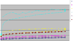
CCR 501 – y = 1.4376x + 100.02
CCR 501/NSP – y = 1.6546x + 175.52
400
200
0
0 20 40 60 80 100 1/s 120

.
Shear Rate
Anton Paar GmbH
0.1
200

0

10
0 20 40 60 80 100 1/s 120

.
Shear Rate
Anton Paar GmbH
NSP – y = 2.1633x + 243.28
VISCOLITE OS – y = 3.5889x + 458.73
VISCO 30 - y = 4.889x + 558.24
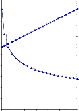
Viscosity = 6000 6800
Yield Value = 215.32 1020.1
Shear Viscosity = 7.34 12.31
Fig 3.3.4 WSPT- After Sampling & After 48 hrs
WSPT – y = 16.173x + 1144.1
IJSER © 2015 http://www.ijser.org
International Journal of Scientific & Engineering Research, Volume 6, Issue 4, April-2015
ISSN 2229-5518
1714
3500
3000
2500
2000
1500
1000
500
0
Fillers After 48 hrs


0 20 40 60 80 100 120 140
Shear Rate, /sec
700
600
500
400
300
200
100
0
Fillers Viscosity after 48 hrs


0 20 40 60 80 100 120 140
Shear Rate,/sec
CCR 501 – y = 1.446x + 101.01
CCR 501/NSP – y = 1.7203x + 173.39
NSP – y = 2.1452x + 239.61
VISCOLITE OS – y = 3.4985x + 479.73
VISCO 30 - y = 5.169x + 554.11
WSPT – y = 15.098x + 856.59
Fig 3.4.1 Shear Stress vs Shear Rate graph of samples after Sampling and after 48 hrs
Dilatancy, also known as shear thickening, is an unusual phenomenon whereby materials actually increase their viscosity upon stirring or shearing. In some cases these are dense suspensions of solid particles in a fluid medium, which develop greater spacing between particles during agitation.As we can see there is not much difference in the behaviour of fillers after 48 hrs. WSPT -- Materials that may behave the same at one end of the flow curve may show dramatic difference at the other, which relates to structural differences in these materials
3.4 Shear Rate vs Viscosity Graph by using Data Points obtained by Rheometer
CCR 501 – y = -0.5706x + 61.65
NSP – y = -1.3345x + 143.01
VISCO 30 - y = -2.8775x + 309.53
WSPT – y = -3.7349x + 412.52
CCR 501/NSP – y = -0.9799x + 105.1
VISCOLITE OS – y = -2.6508x + 283.36
Fig 3.5.1 Shear Rate vs Viscosity graph of samples after
Sampling and after 48 hrs
The viscosity of a material according to the rate at which it is sheared, provides important information about processing and performance12. This can be important in production where stirring, dispensing and pumping of the product will subject it to a variety of shear rates. Low shear rate behavior can be related to storage conditions of materials: sedimentation, phase separation, and structure retention.It can easily be deduced from this everyday example that the relationship between applied shear force and viscosity is nonlinear. There is little change in viscosity up to a certain level of applied shear force, whereas beyond this level, there are significant changes n
viscosity as shear force is increased.
Fillers Viscosity after Sampling

700
600
500
NSP
CCR-501
VISCO-30
3.6 Three Interval Thixotrpy Test
1. CCR 501 2. Neolite SP
400
300
200
W SPT
CCR-
501/NSP
VISCOLITE OS
Rheoplus

2
10
Rheoplus
3

10

NSP 3IT 1
100
0
0 20 40 60 80 100 120 140
Shear Rate, per sec
Pa·s


1
CCR 501 1
CC17-SN3382; d=0 m m

Vis cos ity
CCR 501 1 [3ITT]
Pa·s
2

10
CC17-SN3382; d=0 mm

Viscosity
NSP 3IT 1 [3ITT]
CCR 501 – y = -0.5657x + 61.122
NSP – y = -1.3571x + 145.4
VISCO 30 - y = -2.9304x + 314.74
WSPT – y = -3.979x + 443.58
CCR 501/NSP – y = -1.0043x + 107.58
VISCOLITE OS – y = -2.5132x + 268.99
10
0
10
0 500 1,000 1,500 s 2,000

Time t
Anton Paar GmbH
Delta=104.79 % after t=60 s

Vis cos ity
1
10
0
10
0 500 1,000 1,500 s 2,000

Time t
Delta=99.389 % after t=60 s

Viscosity


Anton Paar GmbH
Structure Recovery Ratio – 104.79% after 60 sec 99.389% after 60 sec
IJSER © 2015 http://www.ijser.org
International Journal of Scientific & Engineering Research, Volume 6, Issue 4, April-2015
ISSN 2229-5518
1715
3. VISCO 30 4.WSPT
Rheoplus
Rheoplus
3

10
suspended. According to some Industries, Thixotropic
materials must lose structure during shear, and rebuild it on standing. This behavior is a key factor in the ability of a paint to
3
10


Pa·s
2
10

VISCO 30 3IT 1
CC17-SN3382; d=0 m m

Vis cos ity VISCO 30 3IT 1 [3ITT] Delta=111.22 % after t=60 s

Vis cos ity
Pa·s

2
10
WSPT 3IT 1
CC17-SN3382; d=0 m m

Vis cos ity WSPT 3IT 1 [3ITT] Delta=101.16 % after t=60 s

Vis cos ity
be easily applied to a surface (through structure breakdown in
spreading) and then rebuild its structure and viscosity so that it does not drip and run. Rheological tests are used widely to evaluate functional coatings in terms of their properties and
1
10 

0
10
0 50 100 150 200 250 300 350 s 400

Time t
Anton Paar GmbH

1
10
0 100 200 300 s 400

Time t
Anton Paar GmbH
performance. During manufacturing as they are mixed and transferred, and during application by spraying, brushing, coating, or dipping, coatings are subjected repeatedly to shear and extension over a range of magnitudes, rates and
Structure Recovery Ratio – 111.22 after 60 sec 99.267% after 60 sec
5. Viscolite OS
Rheoplus
durations14-15.
V ACKNOWLEDGEMENT
3

10
Pa·s
2
10

1
10
VISCOLITE OS 1
CC17-SN3382; d=0 m m

Vis cos ity VISCOLITE OS 1 [3ITT] Delta=99.267 % after t=60 s

Vis cos ity
We are thankful to Pradeep Verma, Managing Director, Henkel Teroson India Ltd (A German Venture), Gurgaon, India for permitting to carry out and publishing this work.

0
10
0 100 200 300 s 400

Time t
Anton Paar GmbH
Structure Recovery Ratio – 101.16% after 60 sec
Structure recovery ratio of CCR 501 is better than other fillers. Visco 30 has also high structure recovery ratio but it has high cost. Hence CCR 501 is preffered.
IV CONCLUSION
The viscosity of thixotropic materials does not follow the same path on structure breakdown and recovery. In most cases, when the shear rate is slowed, the stress path lags forming a hysteresis loop, which then returns to a point lower than the initial critical shear stress13. The area within the hysteresis loop represents the energy consumed in structure breakdown. From above data, conclusion can be drawn that slope can give us modulus , If modulus is high ,material is highly rigid ,it means less flexible like WSPT is very less flexible ,it can be used according to the applications. But CCR 501 will be better filler for PVC for use in automotive applications. For PVC, the material whose viscosity is decreasing when high shear rate is applied is preferred like UBC (Under Body Coating).But for Mastic we have to consider other parameters also like Sagging tendency based on its application. Many factors affect the stability of structured fluids. The viscosity of the liquid phase in dispersions usually plays an important role on the flow properties of the material. Dispersions have wide variations in performance depending on particle size, shape, concentration, and compatibility with the continuous phase in which they are
VI REFRENCES
1) Von Moody, Howard L Needles,(115-123),2004
2) Hassane Boudhani Carole Lainé René Fulchiron Véronique
Bounor-Legaré Philippe Cassagnau Polymer Engineering
& Science 49, (1089–1098), June 2009
3) Paola Persico, Hongbing Ji Veronica Ambrogi, Domenico Acierno and Cosimo Carfagn Journal of Vinyl and Additive Technology 15, (139–146) 2009,
4) S. Jack Willey and C. W. Macosko Journal of Rheology / Volume 22 / Issue 5
5) Cook, John A 1986 Institute of Polymer Engineering, 213 (100–106), Issue 1, 13 August 1986
6) N. Nakajima, E.R. Harrell journal of Colloid and Interface science, 238. issue 1,(105-115), June 2001
7) N. Nakajima and D. W. Ward November, 54 (1096-
1112)1981


8) Nuria Burgos , , Alfonso Jiménez 94, Issue 9, (1473-1478
),September 2009,
9) M.N. Sathyanarayana, M. Yaseen 26, Issues 2–4,(275313), September–December 1995,
10) E. A. Collins, D. J. Hoffmann, P. L. Soni Rheology of Plastisols of Poly (Vinyl Chloride) 52 (676-691), Issue 3, July 1979
11) Applied rheology in polymer processing by B.RGupta
12) Polymer science by Gowarikar .
13) http://en.wikipedia.org/wiki/Rheometer
14) FILLERS IN PVC A REVIEW OF THE BASICS Henry
IJSER © 2015 http://www.ijser.org
International Journal of Scientific & Engineering Research, Volume 6, Issue 4, April-2015
ISSN 2229-5518
1716
15) Wiebking Specialty Minerals Inc. 640 N. 13 St., Easton, PA
18042 November 13, 1998
http://en.wikipedia.org/wiki/Plastisol
IJSER © 2015 http://www.ijser.org