International Journal of Scientific & Engineering Research, Volume 5, Issue 9, September-2014 935
ISSN 2229-5518
Review paper on Design and Computational
Analysis of Air Flow through Cooling Duct
Mr. Virendra V. Khakre1, Prof. Avinash M. Wankhade2
Abstract-This paper focuses on study of design and modifications air cooling duct using Computational Fluid Dynamics (CFD) analysis considering all air flow features relating to the duct system efficiency. Adequate tools and methods are now to design efficient air-cooling systems. Failure in correctly applying different load conditions to the structure of ducts and the layout of the ducting system leading to problems such as uneven cooling across the cooling space, greater frictional losses, steeper installation costs & increased noise and power consumption levels. The above cooling issues highlight the need for optimizing duct design especially to provide improved flow conditions. It combines theoretical and software enabled tools to provide a detailed comparative analysis of the costs and benefits involved in selecting a particular shape (rectangular or circular) of duct for a prescribed situation. The focus of this paper will be on using CFD software tools to study velocity distribution of air in the duct at various sections, pressure difference at various outlets and distribution of air flow for different load conditions.
Index Terms-Air Duct, CFD, Air Flow
—————————— ——————————
1. INTRODUCTION
Earlier the use of air-conditioning for comfort purpose was considered a luxurious but now-a-day, it has been a necessity in extreme climatic conditions, such as extreme cold and hot in western countries. Window air conditioners are preferred for office rooms while large centralized units are installed for conditioning the auditorium, hospitals etc. The correct estimation of cooling load of large area is very complicated due to many factors such as outdoor temperature, humidity, air leakage into the conditioned space, occupants, quantity of fresh air taken in and solar load etc. The climate condition at workplace like offices, workshops is also important factor while selecting optimum design for air cooling duct, this results in efficient and comfortable working conditions. In order to achieve required cooling load, proper method is required. Proper air distribution is achieved with proper duct design which leads minimum losses in the system, suitable selection of fan with high efficiency, optimum air velocity in duct, inlet and outlet of fan. Today some software’s are available to estimate cooling load, to design the duct, to select the fan etc.CFD as a analysis tool has the ability to establish firm quantitative data regarding air motion and can predict fluid characteristics and pressure differentials to a very low level that are experimentally impossible during experimentation. Analysis of air flow in duct with static pressure and velocity pressure is made easier and faster in Fluent software. The requirement of air conditioner is that it must provide adequate cooling to the occupants in the conditioned space under a wide variety of ambient conditions. A normal healthy person feels comfortable at 25°C DBT, 50% RH with 9 to 12m/min air velocity. Human comfort is influenced with the physiological conditions determined by the internal heat generation.
2. DESIGN OF AIR DISTRIBUTION SYSTEMS BASED ON FLUID FLOW ANALYSIS
The project will include the analysis of 2 shapes viz. Circular and Rectangular cross-section ducts and selection of one which encounters minimum distribution losses The principles of Computational Fluid Dynamics (CFD) was applied for fluid flow analysis, by using the
following tools:-
• Fluent – A commercial software package used to simulate the pressure drop inside the duct.
• Gambit – Pre-processor for Fluent used to build the
3-dimensional computer model of the two types of ducts.
The project broadly consists of three main phases. Firstly, designing the air conditioning system and calculating the specifications of the AHU (Air Handling Unit), thus enabling to determine the size of the ducts. This stage establishes the dimensions of the flow field quintessential to the subsequent stage of CFD analysis.

Figure 1:- Effective duct layout
A CFD model will be generated for a square and circular shaped duct based on the premise that the area of cross-sections of each of the shapes is the same. This will ensure the same amount of material
IJSER © 2014 http://www.ijser.org
International Journal of Scientific & Engineering Research, Volume 5, Issue 9, September-2014 936
ISSN 2229-5518
being used in each of the above cases. The following sequence of steps will be followed to obtain the desired results while performing the software analysis: Creating geometry in GAMBIT>Meshing in GAMBIT>Setting boundary types in GAMBIT>Setting up problem in FLUENT>Solving and obtaining solutions in FLUENT.
3. DESIGN OPTIMISATION OF INDUSTRIAL DUCTS USING COMPUTATIONAL FLUID DYNAMICS
The main objective of this work is to provide improved flow conditions in to the top of a gas furnace wind box and along the duct with no recirculation, minimum pressure losses and low turbulence levels. A geometrically 3D CFD model was assembled to capture the complex air pre-rotation before approaching the blower, air circulation in the blower region and airflow in the duct system to a boiler.
First the CFD model was validated with experimental data at three fan Variable Inlet Valve (VIV) percentage openings. Then a parametric study was carried out to remove recirculation regions in the duct. In this study CFD analysis was used to optimize the design of a number of industrial duct the ducts were used to provide air to a gas boiler in a power station. The ducts were historically suffering from low efficiency due to air circulation inside the duct, high turbulence
intensity into the top of gas furnace wind box and pressure differentials at burner injector inlets. In this analysis he analyses two duct systems and provided preliminary design concepts for the redesign of the systems based on a detailed flow analysis and acoustic analysis. The paper focus on fluid flow result analysis.
4.“A PROCEDURE FOR PREDICTING PRESSURE LOSS COEFFICIENTS OF DUCT FITTINGS USING CFD”
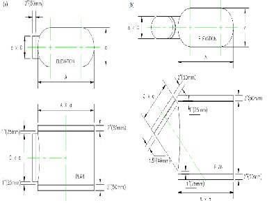
ASHRAE provided two sets of duct fittings for the competition: a flat oval with tee junction and a flat oval with lateral junction. The material of the duct fittings is galvanized steel, and the surface roughness ε of the duct fittings provided by AHSRAE is 0.09 mm (0.0003 ft). By using the duct fitting for the converging and diverging flows, a total of four cases stipulated by the competition were studied:
Case 1: flat oval straight body with tee junction for converging airflow,
Case 2: flat oval straight body with tee junction for diverging air flow, Case 3: flat oval straight body with lateral junction for converging airflow, and
Case 4: flat oval straight body with lateral junction for diverging air flow.
Investigation extended the simulated domain according to the standard lab test apparatus in compliance with ASHRAE Standard
120, as we believe that any tests should comprise the standard as well. The length of the straight duct in the upstream was 11.5 times that of the inlet hydraulic diameter, and the length of the straight duct in the downstream was 15 times that of the outlet hydraulic diameter. The surface roughness of the straight duct was not provided by ASHRAE and is probably unknown. The inlet velocity ranged between 5.1 ~
20.3 m/s (1000 ~ 4000 fpm), corresponding to a common section Reynolds number of 85,000 to 500,000. To keep the airflow rate and flow ratios varied over a reasonably wide and realistic range from 0.1 to 0.9, the inlet boundary conditions and flow ratios used in this study. The inflow turbulence intensity provided was 10% as provided by the ASHRAE.
Figure 2 a) Diverging and b) converging air flow test apparatus
used by ASHRAE standard 120
Figure 2:- a) Diverging and b) converging air flow test apparatus used by ASHRAE standard 120
5. DUCT SYSTEMS IN LARGE COMMERCIAL BUILDINGS
This paper describes research with two primary objectives:
1. To characterize energy losses in the duct systems within large commercial buildings, along with the pertinent physical features of the ducts.
2. To develop and evaluate methods of measuring duct system energy losses.
The research on large commercial ducts includes modeling to quantify the influence of these losses on HVAC system energy use and an investigation of the feasibility of sealing ducts in large commercial buildings by injecting sticky aerosols into the ducts.
Research methods
1) Duct system physical characterization
2) Measuring temperature gains in duct systems
3) Isolation of sections of ductwork
4) Duct system effective leakage area (ELA) measurements
5) Duct system pressure measurements
6) Measurement of rates of air flow through supply registers
7) Measurement of air flow rates at duct cross sections
8) Measurement of air-leakage rates in duct systems
6. DUCT DESIGN USING EQUAL FRICTION METHOD & CFD
Cooling Load Temperature Differential (CLTD) / Cooling Load Factors (CLF) / Solar Cooling Load (SCL) is used to calculate the cooling load of an auditorium. It was an attempt to simplify two steps TFM & TETD /TA methods into a single step technique that allowed proceeding directly from raw data to cooling load. A series of factors were taken from cooling load calculation results as
‘Equivalent Temperature Difference’ for use in traditional
IJSER © 2014 http://www.ijser.org
International Journal of Scientific & Engineering Research, Volume 5, Issue 9, September-2014 937
ISSN 2229-5518
condition (q = UA dT) equation. The conditioned air (cooled or heated) from the air conditioning equipment must be properly distributed to rooms or spaces to be conditioned in order to provide comfort conditions. When the conditioned air cannot be supplied directly from the air conditioning equipment to the spaces to be conditioned, then the ducts are installed. The duct systems convey the conditioned air from air Duct material is usually made from galvanized iron sheet metal, Al sheet metal or black steel. But now a day, the use of non-metal ducts has increased. The resin bonded glass fiber ducts are used because they are quite strong and easy to manufacture according to desired shape and size. They are used in low velocity applications less than 600m/min and for static pressures below 5mm of water gauge.
General rules used to design air duct
i) Air should be conveyed as directly as possible to economize on power, material and space.
ii) Sudden changes in direction should be avoided. When bends are essential, turning vanes should be used to minimize pressure loss.
iii) Air velocities in ducts should be within permissible limits to minimize noise.
iv) Diverging sections should be made gradual. The angle of divergence should not exceed 200.
v) Rectangular ducts should be made as nearly square as possible. This will insure minimum duct surface, and hence cost, for the same air carrying capacity. Dampers should be provided in each branch outlet for balancing the system.
vi) Avoid duct obstructions
Methods of duct design
i) Equal Friction Method
ii) Velocity Reduction Method iii) Static Regain Method
7. CFD SIMULATION AND ANALYSIS OF THE COMBINED EVAPORATIVE COOLING AND RADIANT CEILING AIR-CONDITIONING SYSTEM
In this paper disadvantages as large air duct and high energy consumption of the current all- outdoor air evaporative cooling systems used in the dry region of Northwest China, as well as the superiority of the ceiling cooling system in improving thermal comfort and saving energy, a combined system is presented. It combines an evaporative cooling system with ceiling cooling, in which the evaporative cooling system handles the entire latent load and one part of the sensible loads, and the ceiling cooling system deals with the other part of sensible loads in the air-conditioned zone, so that the condensation on radiant panels and the insufficiency of cooling
capacity can be avoided. The cooling water at 18℃ used in the cooling
coils of ceiling cooling system can be ground water, tap water or the cooled water from cooling towers in the summer. This new
air-conditioning system and existing all- outdoor air evaporative cooling system are applied to a project in the city of Lanzhou. Energy consumption analysis of the building is carried out using the energy consumption code. Velocity and temperature distribution in the
air-conditioned zone is computed using CFD. According to the results, the energy consumption and indoor human thermal comfort of both systems are then compared. It is concluded that the new system occupies less building space, reduces energy consumption, improves indoor human thermal comfort and saves initial investment. Energy consumption analysis of the building is carried out using energy
consumption code and velocity and temperature distribution in the air-conditioned zone is computed using CFD.

Figure 3:- system 1
Figure 4:- system 2
8. CONCLUSION
The following various conclusions summarize the present paper
1) The cooling load calculation of an auditorium is done, applying various methods and duct design is carried out by equal friction method. All results are comparable with existing plant by author.
2) The calculated value of frictional pressure drop is less as compared to existing plant or value used in industry. Due to less value, duct diameter is increased but loss in static pressure, velocity pressure
IJSER © 2014 http://www.ijser.org
International Journal of Scientific & Engineering Research, Volume 5, Issue 9, September-2014 938
ISSN 2229-5518
can be avoided. Smaller diameter of duct would increase noise level. So requirement of sound attenuating devices may need. Also probability of dampers is decreased with increasing diameter. But first cost is increased with increasing duct diameter.
3) Due to proper branching (with elbow) of ducts, loss is minimized in this design. But in existing plant, there is straight branching in so many locations, which may increase the pressure loss.
4) Pressure loss in duct fitting is kept minimum by using elbow with proper shape considering very less pressure loss coefficient.
5) CFD software is used to analyze the air flow in straight duct and in elbow. Eddies are observed due to incorrect shape of elbow. So proper shape of elbow and correct velocity are estimated to minimize the eddies as well as pressure loss.
6) CFD can be used to study pressure and velocity fluctuation for a whole building. So it is a better tool which can be used in HVAC system to save time and cost
REFERENCES
[1] T. Mathewlal1,” DESIGN OF AIR DISTRIBUTION SYSTEMS BASED ON FLUID FLOW ANALYSIS”, Third Biennial National Conference on Nascent Technologies Fr. C. Rodrigues Institute of Technology, Vashi, Navi Mumbai, Feb 24-25, 2012
[2] Dr. Neihad AL-KHALIDY, “DESIGN OPTIMIZATION OF INDUSTRIAL DUCT USING COMPUTATIONAL FLUID DYNAMICS”, Third International Conference on CFD in the mineral and Process Industries, CSIRO, Melborne, Australia, 10-12
December 2003.
[3] Wei Liu,” A PROCEDURE FOR PREDICTING PRESSURE LOSS COEFFICIENTS OF DUCT FITTINGS USING CFD” HVAC&R Research, 18(6), 1168–1181.
[4] William J. Fisk, “DUCT SYSTEMS IN LARGE COMMERCIAL BUILDINGS”, Energy and Buildings 32 ,(2000) 109–119.
[5] Raviraj Gurav, “DUCT DESIGN USING EQUAL FRICTION METHOD AND CFD”, International Conference on recent technology 2012, 9-11 February 2012.
[6] Huang Xiang, “CFD SIMULATION AND ANALYSIS OF THE COMBINED EVAPORATIVE COOLING AND RADIANT CEILING AIR-CONDITIONING SYSTEM”, HVAC Technologies for Energy Efficiency Vol.IV-3-3.
AUTHOR BIOGRAPHY
1. Mr. V.V.Khakre, (PG Student, Department of Mechanical
Engineering, BNCOE,Pusad.)
2. Prof. A.M.Wankhade, (Assistant Professor, Department of
Mechanical Engineering, BNCOE,Pusad)
IJSER © 2014 http://www.ijser.org