International Journal of Scientific & Engineering Research, Volume 5, Issue 1, January-2014 934
ISSN 2229-5518
Redesigning of the combustion chamber for small scale static thrust turbojet engine.
Sandeep Kumar Singh, Dr. S.S. Mondal
Abstract : A research project was conducted at IIT-BHU, Varanasi for the development and redesigning of a turbojet engine for small scale applications and to enhance its commercial viability. The paper describes, in detail all the phases required to set up the combustion chamber of such turbojet engine: designing, manufacturing approach and operational aspects .The idea is to remodel the combustion chamber and devise a different operational methodology while retaining the basic structure and maintaining the prime operational integrity as that of conventional engines. The new model complies with compactness, cost effectiveness and helps in moderation of the emissions.
Keywords: combustion chamber, flame tube, propulsion, recirculation, redesigning, turbojet engine, turbulence
1. INTRODUCTION
Recent advancement in technology and increasing
encounter the challenges of proper flame stabilization and
IJSER
energy demands has inclined the research to more
energy efficient engines. Apropos to the current scenario, commercial viability of the small scale turbojet engine, because of their potential application by virtue of compactness, very high thrust-to-weight ratio and high energy density has emerged as one of the most sought for options. A lot of attempts have been made to scale down the turbojet engines however understanding precise behaviour of such engines is still conundrum including almost all phases.
The designing and manufacturing of such engines is quite difficult. The approach for designing has to account for some additional considerations compared to conventional engines due to their small size
Reynolds number predominantly influences the designing criteria of such low operational pressure ratio machines [1], [2]. Also this include high thermo-mechanical stresses [2] due to the high speed rotating elements and elevated operational temperatures, calling for proper heat dissipation methods.
Moreover, designing of combustion chamber has to

Sandeep Kumar Singh is currently working as Asst. Design Engineer at
Mecon Limited, India. Email: sandeep.mec08@iitbhu.ac.in
Dr. S S Mondal is Assistant Professor at Mechanical Engineering Dept., IIT (BHU), India . Email: mondal_1976@yahoo.com
propagation through different zones marked by optimum
equivalence ratio and velocities of the combustion mixture [3], [6]. Annex to that, set-up for recirculation is also required for an efficient working.
Manufacturing aspects are in accordance of choice of proper operational parameters which directly influences the selection of the material. This selection and engine architecting should be optimized so as to meet the thermo- aero-mechanical stress demands during operation, heat transference and possess required machinability. However, accurate machining and precise static and dynamic balancing of the rotary elements is also important for development of a highly sophisticated and efficient machine with high operational tolerance and better off- design performances.
The rationale is to modify and redesign the combustion chamber to assist in development of a small scale turbojet engine, using existing and proven technology along with new design and modification to be used as a commercial unit as well as for academic purposes
2. DESIGNING SPECIFICATION
The designing specification of a turbojet engine includes the desired compression ratio, optimum turbine inlet temperature and requisite thrust output depending upon the application.
IJSER © 2014 http://www.ijser.org
International Journal of Scientific & Engineering Research, Volume 5, Issue 1, January-2014 935
ISSN 2229-5518
.
The machine is essentially compact in size and a cost effective in production.
The different aspects considered during the designing of such engine includes-
1. Selection of a thermodynamic cycle [5]. The working of the system is governed by Open Brayton-Joule cycle with air as a working fluid. Moreover no regeneration, reheat or intercooling is considered for the analysis.
2. The rotary elements of the machine, compressor and turbine are mounted on single connecting shaft, similar to conventional engines, which also enhances the compactness of the system. The bearing and ‘windage’ frictional losses in work transmission from compressor to turbine are
ignored [2].
2. Fuel and air mixture behaves as semi-ideal gas , with variable enthalpy , specific heats and change in the equivalence ratio due to change in temperature and due to internal combustion
,change in chemical composition.
3. Ambient conditions for the working fluid, air temperature is 298.15K and pressure is 101.3 kPa.
4. Compressors isentropic efficiency is 0.86
5. Combustor burner efficiency is 0.98
6. Combustion chamber pneumatic efficiency is 0.96
7. Turbine isentropic efficiency is 0.88
8. The change in kinetic energy at inlet and outlet of each component is ignored.
9. The fuel employed is propane, generally used for household purpose with a calorific value of 49800 kJ/kg.
A value for the specific output (power per unit mass flow
IJSER
3. The compression ratio of the system is also kept at
lower side so as to simplify engine architecture and avoid thermo-mechanical stresses during operation at high speeds, thus reducing the need of air bleeding and blade cooling.
4. The selection of proper operational parameters to limit the turbine inlet temperature to approx. 1000
K. This provides better spectrum for choice of low cost and high machinable material.
5. Usage of standard turbo machine and blade design techniques and practices so as to make the system analysis and configurations as simple as possible accounting fundamental to all phases.
3. DESIGN PROCEDURE
of air) was determined, 200N/kg/s and specific fuel consumption was determined for various values of cycle parameters listed above .The air flow requirement thus obtained as 0.071 kg/s was utilised to determine the engine size. The pressure ratio of 1.26 was employed with the turbine inlet temperature as 1000K.
Consequently, the mechanical designing comprising the annulus dimensions and rotational speed was carried out, in accordance with the manufacturing feasibility .At last the mechanical designing of the engine was done to check out the unbalance and vibration problems.
Table1: Parameter obtained from cycle analysis
3.1 Approach :
The parametric (design point) analytical approach is used for analysis, which helps in determining the performance of the engine at different flight conditions , values for design choice and design limits. A thermodynamic design point study is carried out by modelling for the system based on Brayton-Joule cycle [5].The following assumptions [2],[ 4] were made for the study;
1. Air behaves equivalent to a semi-ideal gas, with variable specific heats and enthalpy throughout the cycle due to change in temperature and chemical characteristics.
IJSER © 2014
3.2 Compressor design:
The compressor is a backward sweep impeller type which can have a high range of specific speeds and are more
http://www.ijser.org
International Journal of Scientific & Engineering Research, Volume 5, Issue 1, January-2014 936
ISSN 2229-5518
energy efficient. The three dimensional simulation and analysis of the compressor setup was done on ANSYS 14.0, BLADEGEN, TURBOGRID and CFX-Solver using parameters obtained from cycle analysis as boundary conditions. Convergence criteria of 1e-4 and 100 iteration were set for the analysis. The data thus gathered was used for prediction of the compressor characteristics. The compressor features the exit blade angle -23.1 degrees and has 12 blades and splitters with compression ratio of 1.26. Impeller has a hub diameter of 12.85 mm, Impeller shroud diameter 35.95 mm and Blade thickness is 0.50 mm. The intake and the compressor casing were made up of aluminium alloy.
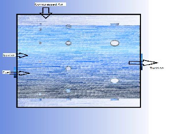
3.3 Combustion chamber design:
Such type of the combustor have two concentric chambers
– outer combustion chamber and a flame tube placed inside. The air from the compressor is made to enter the outer combustion chamber using a duct which also supports as a diffuser. The dimension of the duct is so decided to reduce the skin friction losses as low as possible. The fuel is injected through a spray nozzle directly inside the primary zone [10] in axial direction to the combustion chamber. The igniter is also mounted at the cover seal plate of the combustion chamber parallel to the fuel supply as shown in fig.
The combustion chamber designing is one of the most typical task and it is still much less amenable to theoretical treatment as compared to other components of the engine. In addition, small scale combustion chambers offers the limitations of compact dimensions i.e. short length and diameter and its limited size makes it hard to be machined and manufacture with high precision.
Hence , these requirements has encouraged us to redesign and modify the model of the existing combustion chamber in a pragmatic way to effectively utilise the space , maintain compactness , reduce capital cost while maintaining operational viability.
Mathematical modelling using ANSYS 14 and CFX solver with convergence criteria of 1e-4, was carried out and the data thus obtained from analysis was used for manufacturing the chamber.
Reynolds number plays a very important role in the designing process. It is the measure of range of scale present in the flow. Turbulence of fluid elements allow momentum
,species and energy to be transported in cross stream direction much more rapidly than molecular diffusion process controlling transport in laminar flow[7] . Results [1],[7] schematically illustrate this development of increasing finer small scale turbulence with increasing Reynolds number, while the largest scale in the flow remaining unchanged. A relation between Kolmogorov micro scale, integral scale or turbulence micro scale and dissipation rate and their dependency with the Reynolds number [8],[9] indicates the dimension at which dissipation of kinetic energy to fluid internal energy can occur. Size of the scale of the turbulence in relation to laminar flow thickness determines the character of turbulent flame [9].
Fig 1: Schematic diagram of combustion chamber
IJSER © 2014 http://www.ijser.org
International Journal of Scientific & Engineering Research, Volume 5, Issue 1, January-2014 937
ISSN 2229-5518
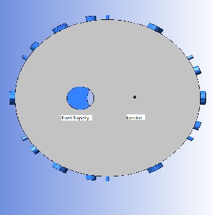
Fig 2 : Cross sectional view of the flame tube
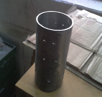
Fig 4: Manufactured flame tube
The air from the compressor fills up the outer chamber initially .The combustor has a length of 173 mm and size of outer and inner chamber is 160 mm and 136 mm respectively. Flame tube consists of 12 no. of annular air inlets placed at an angle of 30 degrees and are made tangentially at the circumference of the flame tube (referred as type A) with a size of 3 mm diameter. The compressed air is thus forced to enter the flame tube through these air inlets .These type of inlets are specially designed to impart a tangential as well as small axial velocity component to the compressed air entering the flame tube , to the direction of the fuel flow. This motion allows the incoming fuel and air to mix completely with high turbulence levels [11]. Experiment by Masri et al. [12] indicates that the local flame extinction can occur prior to flame blowout showing strong interdependence between turbulence and chemistry. Moreover, an overall
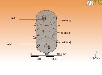
Fig 3: Flame tube with different types of air inlets
IJSER © 2014
characterization of interaction between turbulence and chemical reaction can be obtained by plotting Damkohler No. (Da) versus Reynolds no over range of length scales, Williams [13].
This reaction mixture thus produced is ignited using spark plug which is situated to the opposite side of the air entry in the chamber. The igniter is placed slightly eccentric so as to allow ample amount of time to the air and fuel to mix before ignition in the primary zone [14].
The remaining part of the air passes through the inter space between flame tube and outer case of the combustor. Some amount of the air enters in the primary zone through
http://www.ijser.org
International Journal of Scientific & Engineering Research, Volume 5, Issue 1, January-2014 938
ISSN 2229-5518
the secondary holes , made at an angle of 60 degrees with
7.5 mm diameter (referred as type B), of the flame tube resulting in recirculation [15]. This helps the reaction mixture to take a toroid shape and stabilize the flame. The recirculating gas helps in complete combustion of the mixture and combustion of the incoming fuel by elevating the temperature [16]. The remaining air, enters through tertiary air inlets, (referred as type C) used in dilution zone to lower down the temperature of the gases before its entry to the turbine [2]. These type of air inlets are made at an angle of 90 degrees and have larger diameter of 12 mm to support comparably high volume flow rates.
The combustion chamber is designed with similar system attributes to that of conventional machines but with different arrangement in its functional elements .The relative position of fuel inlet and igniter along with the peculiar direction of the air inlets inside flame tube, allows the components to mix properly and create turbulence. The study carried out by Wohl el at [17] on stability of premixed flames reveal that they are much less stable and the turbulent flame blow off velocity is practically
distribution system has to be carefully designed for high flame stability. The skin friction and losses in the duct for air supply in combustion chamber contributes in the poor aerodynamic performance of the engine. The eccentric position of the burner may also cause some uneven degeneration effects inside the tube but can be managed due its high utility for the system.
3.4 Turbine design
The data collected from the combustion chamber analysis serves the as requisite for the development of turbine. The outlet temperature of the mixture from combustion chamber was near 967 K, with outlet pressure of 4.2 bar. The simulation of the turbine setup was done on ANSYS
14.0, BLADEGEN, TURBOGRID and CFX-Solver was used for analysis using the above boundary conditions. Convergence criteria of 1e-4 and 100 iteration was set for the analysis. The performance output of the turbine indicates the pressure of 1.9 bar .The exiting mixture still
has ample amount of energy that can be harnessed using
IJSER
independent of the tube diameter over a considerable
range. The reason for such a behaviour is the difference between velocity gradient at tube wall and the average velocity and generally flows between 5000 and 200,000 is employed. But accounting to the high speed of compressed air ,the system is modelled as a semi- premixed air fuel mixture since the premixed combustion is much more difficult to achieve and also requires more degree of sophistication in design ,modelling and is difficult to manufacture [18] . Also, premixed systems are avoided as they may result in auto ignition and less stability in the system. Different type of air inlets (namely type A, B, C) are specially designed to regulate the air distribution. Correct placement of secondary (type B) air inlet effectively improves the recirculation, regulates the flame propagation and helps in complete combustion of the reaction mixture [2], [11]. This acts as a cost effective alternate to swirl vanes, which are much difficult to manufacture and model. The remaining proportion of the compressed air moving along interspace of the concentric chambers also helps in liner cooling before entering dilution zone. The regulation of flame temperature by proper air circulation technique also helps to maintain the emission level and check NOx levels Thus, this configuration meets the requirement of a compact and cost effective machine having satisfactory fuel-air mixing and liner cooling.
However, due to specific range of input demands this configuration has narrow operational ranges and flexibility when subjected to change in the equivalence ratio. The air
IJSER © 2014
improved turbine and nozzle design.
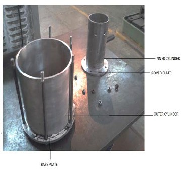
4 ASSEMBLY DESIGN
The different components of the turbojet are assembled as per conventional arrangements. The combustion chamber is so designed such that it does not has any weld or permanent joint (except for flame tube with its seal plate and duct inlet to combustion chamber ensuring airtight and leak-proof operation) and have ease in reproducibility. The entire combustion system manufacturing is done in primarily two segments using simple techniques only. The bolts, studs and airtight seal are used to assemble the segments.
http://www.ijser.org
International Journal of Scientific & Engineering Research, Volume 5, Issue 1, January-2014 939
ISSN 2229-5518
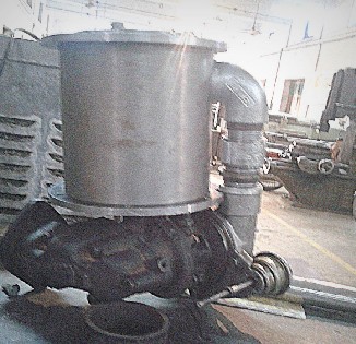
other arrangements were made so as to prepare the system for final testing as shown in fig.
Fig 1: A segmental view of combustion chamber before
IJSETo start up tRhe engine, initially the auxiliary air through a
assembly
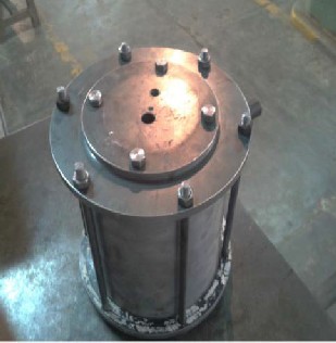
Fig 3: Typical turbojet assembly before testing
PROCEDURE AND RESULT:
secondary compressor was fed directly to the engine compressor to move the impeller and supply essential compressed air in the chamber for mixing with the fuel. Concurrently small amount of gas was allowed to fill the flame tube. The spark was then generated which commenced the fuel ignition. The fuel supply and compressed air volume is also incremented in a controlled manner until the engine is self-operated. The air supply is then removed and fine adjustments were made to sustain the light up (flame).
Fig 2: Assembled combustion chamber
5 TURBOJET TESTING
The developed turbojet engine was assembled and subsequently the fuel connections, igniter position and
The system was also modelled using ANSYS-14 CFX solver tool with the convergence criteria of 1e-4 with 200 iterations .The results thus obtained were in good agreement with those predicted theoretically[19]. The model for simulation and analysis was Eddy dissipation k/Ɛ model [8],[20] in CFX solver. This model was used as it assumes Newtonian relationship between turbulent stresses and main strain rates. The models calculates the local mixing throughout the flow field and invokes the Boussinesq approximation. In such model the reaction rates are assumed to be controlled by the turbulence, so expensive Arrhenius chemical kinetic calculations can be avoided.
IJSER © 2014 http://www.ijser.org
International Journal of Scientific & Engineering Research, Volume 5, Issue 1, January-2014 940
ISSN 2229-5518
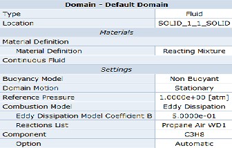
Table 2: Analysis criteria for the combustion chamber 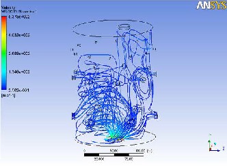
Fig 9: Velocity streamlines at time of cold start inside flame tube
6 CONCLUSION:
Although a sincere effort was put to develop as efficient combustion chamber as possible, by enhancing the system design and operational prospective, but it still calls for further improvements. The turbine inlet section can be improved to avoid thermal stresses due to hot air stagnation, which was as acted due to manufacturing complexity involved. The air distribution system can be improved to reduce improper burning of fuel and check the pollution by regulating the EI (emission index). The project has made possible to acquire the requisite expertise to design, self-operate and manufacture a combustion chamber to be used as a unit in small scale turbojet engine at commercial level.
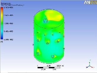
Fig 8: Temperature distribution inside flame tube at cold start
REFERENCES
[1] Turns Stephen R. “An introduction to Combustion: Concepts and Applications” 2nd ed. Singapore: Mc-Graw Hill, 2000.
[2] Cohen H, Rogers GFC, and Saravanamutto HIH “Gas Turbine Theory” 4th ed. London: Longman Group Limited, 1996
[3] Fristrom R M.” Flame structures and Process “New
York: Oxford University Press, 1995
[4] Kuo KK. “Principles of combustion “2nd ed. New
York: John Wiley and Sons, 1986
[5] Cengen YA and Boles MA “Thermodynamics: An
Engineering Approach “5th ed. New York: Mc-Graw Hill,
2006
IJSER © 2014 http://www.ijser.org
International Journal of Scientific & Engineering Research, Volume 5, Issue 1, January-2014 941
ISSN 2229-5518
[6] Mattingly Jack D. “Elements of Propulsion: Gas
Turbine and Rockets “2nd ed. Virginia: AIAA Inc., 2006
[7] Tahry El. “Application of Reynolds stress Model to Engine like flow calculations.” Journal of fluids engineering ASME 1984; 20: 39-46
[8] Spalding DB. “Kolmorov’s two equation model of Turbulence.” Proceedings of Royal Society Of London Series A 1991; 434:211-216
[9] Basso A and Rinolfi R. “Two-Dimensional computations of engine combustion: Comparison of measurement and predictions.” SAE paper 820519, 1982.
[10] Bracco FV. “ Modelling of Engine Spray.” SAE paper
850394, 1985.
[11] Wygnanski ID, Feidler H and Dziomba B. “ On perseverance of a Quasi-two-Dimensional Eddy –Structure in a Turbulent Mixing Layer.” Journal of Fluid Mechanics
1979; 93:325-335
[19] National Aeronautics and Space Administration. Jet propulsion systems, www.grc.nasa.gov/WWW/K-
12/airplane/aturbj (2012, accessed on 23 March 2012).
[20]Wilcox, D.C., “Turbulence Modelling for CFD, DCW
industries,” La Canada, CA, 1993
[21] Ernest Benini, and Stefano Giacometti. “Design, Manufacture and Operation of turbo-jet engine for research purpose.” Applied Energy 2007; 84:1102-1116.
[12] Masri AM, Bilger RW and Dibble RW. “Turbulent non-premixed flames of methane near extinction. “ Combust. Flame 1988; 71: 245-266.
[13] Williams FA. “Structure of flamelets in turbulent reacting flow and influence Of combustion on turbulence fields. “ Lecture Notes in Engineering. Springer 1989; 40:
195-212.
[14] Botha JP and Spaldings DB. “The laminar flame speed of propane – air mixture with heat extractions from flame.” Proceedings of Royal Society of London Series A 1954;
225:71-96.
[15] El Mahallawy F and El-Din Habik S. “ Fundamentals and Technology of Combustion.” Oxford: Elsevier Science Ltd, 2002
[16] Brown GL and Roshko A. “On density effects and Large structure in Turbulence Layer.” Journal Of Fluid Mechanics 1974; 64: 775-816.
[17] Wohl K, Kapp NM and Gazley C . “Diffusion Flames.” In: Third Symposium on Combust. Flame And Explosion Phenomena 1949; 3: 288-300. Baltimore, MD: Williams and Wilkins
[18] Jeffs RA. “The flame stability and Heat Release Rates of Some Can type combustion chambers.” In: English Symposium (International) on combustion 1962; 8: 1014-
1027. Baltimore, MD: Williams and Wilkins.
IJSER © 2014 http://www.ijser.org