
International Journal of Scientific & Engineering Research, Volume 4, Issue 7, July-2013 414
ISSN 2229-5518
Sahil Sood, Chandika Mohan Babu
ABSTRACT-The modern wireless system consists of complex base stations with a high power transmitter in which channel characteristics should be adaptive and dynamic for broadcasting with in defined bandwidth with effective high data rate transmission. The services can be offered in NLOS and LOS with different standards to mitigate the effects of channel fading, intereference, high data rate and channel capacity. But the main challenge is transmission rate and the strength of received signal should be optimized for increased capacity in radio link. The multiple antennas allow MIMO systems to perform precoding (multi-layer beamforming), diversity coding (space-time coding), and spatial multiplexing. By doing MIMO techniques we can achieve higher data rate or longer transmit range without requiring additional bandwidth or transmit power. This paper presents a detailed simulation of coding techniques for MIMO systems with and with out CSI, Spectral efficiency simulation for ergodic capacity and BER analysis is done. Different space-time block coding (STBC) schemes including Alamouti’s STBC for different range of transmitter and receiver is done. Finally, these STBC techniques are implemented in MATLAB and analyzed for performance according to their bit-error rates. In this paper a complete approach and simulations is done for multi-antenna system with capacity and BER of SIMO and MISO systems in Rayleigh fading channels has been examined with CSI and without CSI (Channel state information). In case if channel state information (CSI) is available at the receiver and the transmitter does not know the channel information, it is best to distribute the transmit power PT equally among the antennas and generate the channel matrix H and perform singular-value decomposition (SVD or generalized Eigen-value Re-decomposition). Finally diagonalized the channel and removed all the spatial interference without any matrix inversions or nonlinear processing If the CSI is also available at the transmitter (CSIT), the optimal power allocation can be derived by applying the well-known water filling assuming that the channel coherence time. At low SNR, CSIT will always helps in increasing the capacity and were as high SNR, CSIT increases capacity for systems with Nt > Nr and CSIT has no benefit for systems with Nt ≤ Nr.
INDEX TERMS-- MIMO, STBC, SVD, SNR, BER, CSI, MRC
—————————— ——————————
he major limitation for any service provider with broad- band application is the bandwidth,spectral efficiency and cost effective. Certain technical challenges will araise on
the user demand and type of service requirement for the satis- fication of subscriber with user equipment models. The BTS offers the coverage scenior under the LOS and NLOS keeping in mind about the high data rate and capacity. But the major challenges when NLOS communication is chosen for broad- band wireless application which are operating at different range of frequencies. The implementation of the transceiver model with effective demands of user faces the technical chal- leneges like mitigation of multipath fading and interfer- ence,achieving high spectral efficiency and overcoming inter- symbol intereference. Even though certain potential solutions have been proposed susch as diversity, channel cod- ing,adaptive antennas with modulation and coding, OFDM, spatial multiplexing,equalization and dynamic channel alloca- tion to with stand the telecom market strategies with enor- mous data rate and increase in subscribers. Recent advances in Multiple-input multiple-output (MIMO) technology demonstrate that MIMO wireless communication systems can
————————————————
• Chandika Mohan Babu is Assistant Professor in Lovely Professional Uni-
versity, India, E-mail: Chandika.14736@lpu.co.in
achieve impressive data rates and system performance. They use multiple antennas at the Tx and/or the Rx to increase the Txion rate and the strength of the received signal, as compared with traditional SISO systems. Most importantly, these gains come with no additional increase in bandwidth or transmis- sion power, which are scarce resources; rather, they come at the cost of system complexity.
Multiple antennas [10] can be used at the transmitter and
receiver, an arrangement called a multiple-input multiple- output (MIMO) system. A MIMO system takes advantage of the spatial diversity that is obtained by spatially separated antennas in a dense multipath scattering environment. MIMO systems may be implemented in a number of different ways to obtain either a diversity gain to combat signal fading or to obtain a capacity gain.
Three potential approaches of MIMO [7]
1) Spatial diversity- To improve communication relia-
bility by decreasing sensitivity to multipath fading.
2) Spatial multiplexing- Creation of multiple parallel channels for carrying unique data streams.
3) Beamforming – Antenna arrays used to focus energy in the desired direction
The above three are collectively referred to as MIMO commu- nication can be used to
IJSER © 2013 http://www.ijser.org
International Journal of Scientific & Engineering Research, Volume 4, Issue 7, July-2013 415
ISSN 2229-5518
I. Increase the system reliability (decrease the bit or packet error rate).
II. Increase the achievable data rate and hence system capacity.
III. Increase the coverage area.
IV. Decrease the required transmitted power
The numerical and simulation results obtained using MATLAB are presented for the multi-antenna system channel capacity and bit-error rate in Rayleigh fading channels. It also show the capacity and BER of MIMO systems in Rayleigh fad- ing channels has been examined. It has been seen that the use of multiple antennas increases the capacity although signifi- cant improvement can be achieved using equal or higher number of receive antennas compared to transmit antennas.
2.1.1 DUAL ARRAY MIMO

Fig 1. MIMO various antenna configuration
Multi-user MIMO or MU-MIMO is an enhanced form of MIMO technology that is gaining acceptance. MU-MIMO, Multi-user MIMO enables multiple independent radio termi- nals to access a system enhancing the communication capabili- ties of each individual terminal.MU-MIMO exploits the max- imum system capacity by scheduling multiple users to be able to simultaneously access the same channel using the spatial degrees of freedom offered by MIMO.To enable MU-MIMO to be used there are several approaches that can be adopted, and a number of applications / versions that are available. [1]
![]() (1)
(1)
Fig 2 . Various Antenna Configuration in MIMO
If channel state information (CSI) is available at the receiver and the transmitter does not know the channel information, it is best to distribute the transmit power P T equally among the antennas and the ergodic capacity is written as
![]() (2)
(2)
where λi is the ith eigenvalue of HH*, σn 2 is the noise power.
Fig 3 . BLOCK DIAGRAM FOR MIMO CHANNEL CAPACITY W ITH NO CSIT
If the CSI is also available at the transmitter (CSIT), the opti- mal power allocation can be derived by applying the well- known water filling. Let's assume that the channel coherence time is larger than the interval of updating CSI at the transmit- ter, hence the transmitter has perfect CSI and the power allo- cated on every sub-channel is adjusted based on the instanta- neous CSIT. Then the ergodic capacity can be written as
![]() (3)
(3)
Where ![]() is the power allocated on the ith sub-channel ob- tained by using the well-known water filling. [7]
is the power allocated on the ith sub-channel ob- tained by using the well-known water filling. [7]![]()
, (4)
Where ![]() = max{x,0} and ᶓ is the “water-level” that is given by the criterion
= max{x,0} and ᶓ is the “water-level” that is given by the criterion
![]() (5)
(5)

The singular-value decomposition (SVD or generalized Eigen- value decomposition) of the channel matrix H is H=U∑V where U and V are unitary and ∑ is a diagonally matrix of singular values.
This has diagonalized the channel and removed all the spatial interference without any matrix inversions or nonlinear pro- cessing.
IJSER © 2013 http://www.ijser.org
International Journal of Scientific & Engineering Research, Volume 4, Issue 7, July-2013 416
ISSN 2229-5518

Fig 4. BLOCK DIAGRAM FOR MIMO CHANNEL CAPACITY W ITH CSIT

Fig 6. BLOCK DIAGRAM FOR MRC
Consider a receive diversity system with NR receiver anten- nas. Assuming a single transmit antenna as in the single input multiple output (SIMO) channel , the channel is expressed as
h = [h1h2 ... h N ]
(6)
2.5 MRC
Fig 5 . BLOCK DIAGRAM FOR STBC
for NR independent Rayleigh fading channels. Let x denote the transmitted signal with the unit variance in the SIMO channel. The received signal y 2 CNR_1 is expressed as
y = ![]() (7)
(7)
where z is ZMCSCG noise with E{z![]() } =
} = ![]() . The received sig- nals in the different antennas can be combined by various techniques. These combining techniques include selection combining (SC), maximal ratio combining (MRC), and equal gain combing (EGC). In SC, the received signal with the high- est SNR among NR branches is selected for decoding. Let ϒi be the instantaneous SNR for the ith branch, which is given as
. The received sig- nals in the different antennas can be combined by various techniques. These combining techniques include selection combining (SC), maximal ratio combining (MRC), and equal gain combing (EGC). In SC, the received signal with the high- est SNR among NR branches is selected for decoding. Let ϒi be the instantaneous SNR for the ith branch, which is given as![]()
, i = 1,2,……,![]() (8)
(8)
Then the average SNR for SC is given as![]()
, i= 1,2,……,![]() (9)
(9)![]()
In MRC, all ![]() branches are combined by the following weighted sum
branches are combined by the following weighted sum
(10)
Where y is the received signal in Equation (7) and ![]() is the weight vector. As
is the weight vector. As ![]() from Equation (7), the combined signal can be decomposed into the signal and noise parts, [1] that is,
from Equation (7), the combined signal can be decomposed into the signal and noise parts, [1] that is,
IJSER © 2013 http://www.ijser.org
International Journal of Scientific & Engineering Research, Volume 4, Issue 7, July-2013 417
ISSN 2229-5518
![]()
=![]() (11)
(11)
Average power of instantaneous signal part and that of the noise part in equation (11) are respectively given as![]()
}= ![]() =
= ![]()
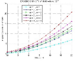
Fig 7. Ergodic Capacity with no CSIT
And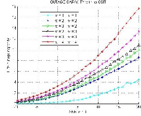
(12)
![]() (13)
(13)
From equation (12)(13), the average SNR for the MRC is given as![]()
Invoking the Cauchy-Schwartz inequality,
(14)
![]()
Equation (14) is the upper-bounded as
(15)
Fig 7. Outage Capacity with no CSIT
![]()
![]() (16)
(16)
Note that the SNR in Equation (16) is Maximized at ![]() , which yields
, which yields ![]() . In other words, the weight factor of each branch in equation (10) must be matched to the corresponding channel for maximal ratio combining (MRC). Equal gain combining (EGC) is a special case of MRC in the sense that all signals from Multiple Branches are combined with equal Weights. In fact, MRC achieves the best performance maximizing the post-combining SNR. [1],[3],[5]
. In other words, the weight factor of each branch in equation (10) must be matched to the corresponding channel for maximal ratio combining (MRC). Equal gain combining (EGC) is a special case of MRC in the sense that all signals from Multiple Branches are combined with equal Weights. In fact, MRC achieves the best performance maximizing the post-combining SNR. [1],[3],[5]
IJSER © 2013 http://www.ijser.org
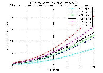
Fig 8. Ergodic Capacity with CSIT
International Journal of Scientific & Engineering Research, Volume 4, Issue 7, July-2013 418
ISSN 2229-5518

![]() =
= ![]() (19)
(19)
![]()
![]()
= (20)
where rT and rR is the fading correlation between two adjacent antenna elements at TXer and Rxer respectively and it is ap- proxmated by the expression given above.
Fig 9. Outage Capacity with CSIT
The signal components at a particular point in space may ex- perience correlation due to the finite separation distance be- tween the antenna elements.
The spatial cross-correlation function, p(r) determines the cor- relation between voltages envelopes separated in space by a distance r.
![]() (17)
(17)
Δ is the angular spread and d is the distance in wavelengths between the antenna elements [10]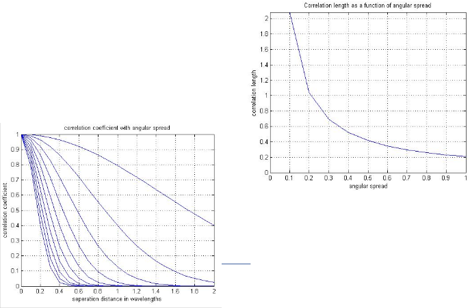
![]()
Now, with fading correlation effect, we model the MIMO
channel H as
H = . (18)
Where Hw is a Nr x Nt matrix with i.i.d complex Gaussian elements. Rr is Nr x Nr reception correlation matrix and Rt is Nt x Nt transmission correlation matrix. First model, in which these matrices are calculated as a function of distance between elements given by the following toeplitz structure correlation matrices for simulation.
Fig 10. Correlation coefficient with angular spread
Fig 11. Correleation length as a function of angular spread
International Journal of Scientific & Engineering Research, Volume 4, Issue 7, July-2013 419
ISSN 2229-5518
ble at the receiver and the transmitter does not know the channel information, it is best to distribute the transmit power PT equally among the antennas and generate the channel ma- trix H and perform singular-value decomposition (SVD or generalized Eigen-value decomposition). Finally diagonalized the channel and removed all the spatial interference without any matrix inversions or nonlinear processing. If the CSI is also available at the transmitter (CSIT), the optimal power allocation can be derived by applying the well-known water filling assuming that the channel coherence time. At low SNR, CSIT will always helps in increasing the capacity and were as high SNR, CSIT increases capacity for systems with Nt > Nr and CSIT has no benefit for systems with Nt ≤ Nr.
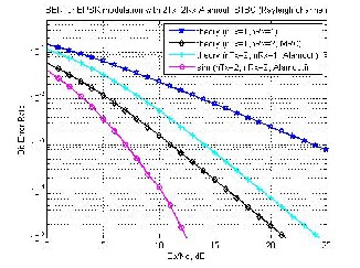
Fig 12. BER FOR BPSK modulation with 2Tx, 2Rx Alamounti
STBC (Rayliegh Channel)
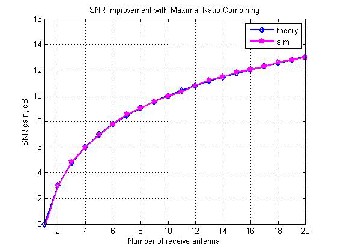
Fig 13. SNR improvement with Maximal Ratio Combining
This paper presents a detailed simulation of coding techniques for MIMO systems with and with out CSI, Spectral efficiency simulation for ergodic capacity and BER analysis is done. Dif- ferent space-time block coding (STBC) schemes including Alamouti’s STBC for different range of transmitter and receiv- er is done. Finally, these STBC techniques are implemented in MATLAB and analyzed for performance according to their bit- error rates. In this paper a complete approach and simulations is done for multi-antenna system with capacity and BER of SIMO and MISO systems in Rayleigh fading channels has been examined with CSI and without CSI(Channel state in- formation). In case if channel state information (CSI) is availa-
[1] F.O. Tade and Y. Sun “ A 4x4 MIMO-OFDM System with MRC in a Rayleigh Multipath Channel for WLAN” Universi- ty of Hertfordshire.
[2] Luis Miguel Cortės-Peňa “ MIMO Space-Time Block Cod- ing (STBC): Simulations and Results ” DESIGN PROJECT: PERSONAL AND MOBILE COMMUNICATIONS, GEORGIA TECH (ECE6604), APRIL 2009.
[3] Srikrishna Bardhan “ Capacity and Performance Analysis of MIMO-STBC in Rayleigh Fading Channels ” International Journal of Engineering Research & Technology (IJERT) Vol. 1
Issue 8, October - 2012 ISSN: 2278-0181.
[4] Qian He, Member and Rick S. Blum “Diversity Gain for
MIMO Neyman–Pearson Signal Detection ” IEEE TRANSAC-
TIONS ON SIGNAL PROCESSING, VOL. 59, NO. 3, MARCH
2011.
[5] Fabian T. R. Barreto, S Y Patni and S Unnikrishnan “En-
hanced Spectral Efficiency using AMC MIMO-OFDM in Wi-
MAX (802.16d) System ” International Conference and Work-
shop on Emerging Trends in Technology (ICWET 2010) –
TCET, Mumbai, India.
[6] Yong Soo Cho , Jaekwon Kim, Won Young Yang and
Chung G. Kang “MIMO-OFDM
WIRELESS COMMUNICATIONS” John Wiley & Sons (Asia)
Pte Ltd, 2 Clementi Loop, # 02-01, Singapore 129809.
[7]http://www.cm.nctu.edu.tw/~IEEEITComSoc/Tutorial_talk_
files/slide/2005_summer/0804CMIMO%20Techniques%20for%
20Wireless%20Communications%20(2005).pdf.
[8]http://cdn.rohdeschwarz.com/dl_downloads/dl_application
/application_notes/1ma142/1 A142_0e.pdf.
[9]Hermann Lipfert “MIMO OFDM Space Time Coding – Spa-
tial Multiplexing Increasing Performance and Spectral Effi-
ciency in Wireless Systems ” (2007).
[10] WHITE PAPER Airspan Networks “Multiple Antenna
Systems in WiMAX ” (2007).
[11] J. Ylitalo & M. Juntti “ MIMO Communications with Ap-
plications ” University of Oulu (2007).
[12] S.M. Alamouti, “A simple transmit diversity technique
for wireless communications”, IEEE Journal Selected. Areas in
Communications, vol. 16, No. 8, Oct.1998, pp. 1451-1458.
IJSER © 2013 http://www.ijser.org