
International Journal of Scientific & Engineering Research, Volume 4, Issue 7, July-2013 473
ISSN 2229-5518
Master of technology 4th Sem. Roll. No. I 118 May 2013
Green Hills Engineering College Solan (Himachal Pradesh Technical University Hamirpur (H.P.)
This paper present an assessment of the “state of the art” in respect to rapid prototyping processes. Based on a variety of reference materials on latest developments of modern RP techniques and the applications of the modern RP techniques. It also to identifying the reasons why these processes have developed and identifying the key features of the process.
KEYWORDS
Rapid prototyping, Material and applications
---------------------------------------------------------------------------------------------------------------------
The first commercial process was presented at the AUTOFACT shows in Detroit’s (US) in November 1987, by Company called 3D systems, Inc. At that time the process was very inaccurate and the choice of the materials was very limited. Therefore, the parts obtained where consider prototypes. Like in software engineering, a prototype is something to look at, serves as bases of discussion but can’t be used for anything “serious”, i.e. in a production environment [1].
Since then, Rapid Prototyping Technologies (RPT) has taken enormous strides. Nowadays, there are over 30 processes, some of which are commercial, while others are under development in research laboratories [1]. The accuracy is high, and the choice of the material is relatively large, to the extent that the term prototype is becoming misleading; the pats are more and more frequently being used for functional testing or to derive tools for pre-production testing.
In addition to prototypes, RP techniques can also be used to make tooling (referred to as rapid tooling) and even production-quality parts (rapid manufacturing). For small production runs and complicated objects, rapid prototyping is often the best manufacturing process available [2].
Fig. 1.1: CAD solid object
Rapid prototyping isn't necessarily very rapid and doesn't necessarily have to do with prototypes, either. Speed is relative: The processes can shave weeks to months off a design cycle, but still may require many hours to fabricate a single object. Prototypes for design evaluation are often made using these processes, but the technology also is beginning to address the direct production of final useful parts and assemblies, and injection moulding and other types of tools. Therefore "rapid" is a relative term. Most prototypes require from three to seventy-two hours to build, depending on the size and complexity of the object. This may seem slow, but it is much faster than the weeks or months required to make a prototype by traditional means such as machining. These dramatic time savings allow manufacturers to bring products to market faster and more cheaply [2].
Fig. 1.2: Converted in STL format object
IJSER © 2013 http://www.ijser.org
International Journal of Scientific & Engineering Research, Volume 4, Issue 7, July-2013 474
ISSN 2229-5518
Because RP technologies are being increasingly used in non-prototyping applications, the techniques are often collectively referred to as solid free-form fabrication; computer automated manufacturing, or layered manufacturing. The latter term is particularly descriptive of the manufacturing process used by all commercial techniques. A software package "slices" the CAD model into a number of thin (~0.1 mm) layers, which are then built up one atop another [2]. Rapid prototyping is an "additive" process, combining layers of paper, wax, or plastic to create a solid object. In contrast, most machining processes (milling, drilling, grinding, etc.) are "subtractive" processes that remove material from a solid block. RP’s additive nature allows it to create objects with complicated internal features that cannot be manufactured by other means [2].
Year of inception | Technology |
1946 | First computer |
1952 | First Numerical Control (NC) machine tool |
1960 | First commercial laser |
1961 | First commercial Robot |
1963 | First interactive graphics system (early version of Computer Aided Design) |
1988 | First commercial Rapid Prototyping system |
RP process belong to the generative (or additive) production processes unlike subtractive or forming processes such as lathing, milling, grinding or coining etc. in which form is shaped by material removal or plastic deformation. In all commercial RP processes, the part is fabricated by deposition of layers contoured in a (x-y) plane two dimensionally. The
Third dimension (z) results from single layers being stacked up on top of each other, but not as a continuous z-coordinate. Therefore, the prototypes are very exact on the x-y plane but have stair-stepping effect in z-direction. If model is deposited with very fine layers, i.e., smaller z- stepping, model looks like original. RP can be classified into two fundamental process steps namely generation of mathematical layer information and generation of physical layer model. Typical process chain of various RP systems is shown in figure 2.1
It can be seen from figure 2.1 that process starts with 3D modeling of the product and then STL file is exported by tessellating the geometric 3D model. In tessellation various surfaces of a CAD model are piecewise approximated by a series of triangles (figure 2.1) and co-ordinate of vertices of triangles and their surface normal’s are listed. The number and
Size of triangles is decided by facet deviation or choral error as shown in figure 2.2. These STL files are checked for defects like flip triangles, missing facets, overlapping facets, dangling edges or faces etc. and are repaired if found faulty. Defect free STL files are used as an input to various slicing softwares. At this stage choice of part deposition orientation
is the most important factor as part building time, surface quality, amount of support structures, cost etc. are influenced. Once part deposition orientation is decided and slice thickness is selected, tessellated model is sliced and the generated data in standard data formats like SLC (stereolithography contour) or CLI (common layer interface) is stored. This information is used to move to step 2, i.e., generation of physical model. The software that operates RP systems generates laser-scanning path (in processes like Stereolithography, Selective Laser Sintering etc.) or material deposition paths (in processes like Fused Deposition Modeling). This step is different for different processes and depends on the basic deposition principle used in RP machine. Information computed here is used to deposit the part layer-by-layer on RP system platform. The generalized data flow in RP is given in figure 2. 3.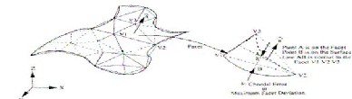
IJSER © 2013 http://www.ijser.org
International Journal of Scientific & Engineering Research, Volume 4, Issue 7, July-2013 475
ISSN 2229-5518
The final step in the process chain is the post-processing task. At this stage, generally some manual operations are necessary therefore skilled operator is required. In cleaning, excess elements adhered with the part or support structures are removed. Sometimes the surface of the model is finished by sanding, polishing or painting for better surface finish or aesthetic appearance. Prototype is then tested or verified and suggested engineering changes are once again incorporated during the solid modeling stage.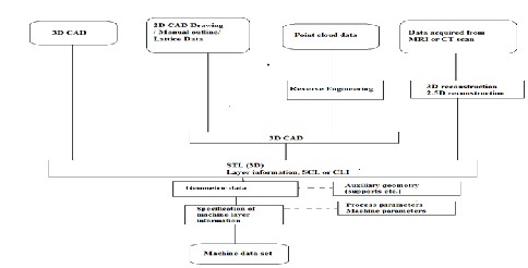
3.1 BASIC PROCESSES
I. Conversion to STL Format: The various CAD packages use a number of different algorithms to represent solid objects. To establish consistency, the STL (Standard Triangulation Language -Stereolithography, the first RP technique) format has been adopted as the standard of the rapid prototyping industry [6]. The second step, therefore, is to convert the CAD file into STL format. This format represents a three-dimensional surface as an assembly of planar triangles, like the facets of a cut jewel. The file contains the coordinates of the vertices and the direction of the outward normal of each triangle. Since the STL format is universal, this process is identical for all of the RP build techniques [6].
II. Slice the STL File: In the third step, a pre-processing program prepares the STL file to be built. Several programs are available, and most allow the user to adjust the size, location and orientation of the model. The pre-processing software slices the STL model into a
III. Number of layers from 0.01 mm to 0.7 mm thick, depending on the build technique [6]. The program may also generate an auxiliary structure to support the model during the build. Each PR machine manufacturer supplies their own proprietary pre-processing software.
build one layer at a time from polymers, paper, or powdered metal [6].
V. Clean and Finish: The final step is post-processing. This involves removing the prototype from the machine and detaching any supports. Some photosensitive materials need to be fully cured before use. Prototypes may also require minor cleaning and surface treatment. Sanding, sealing, and/or painting the model will improve its appearance and durability [7].
3.2 TECHNIQUES OF RAPID PROTOTYPING
The new rapid prototyping technologies are additive processes. They can be categorized by material: photopolymer, thermoplastic, and adhesives. Photopolymer systems start with a liquid resin, which is then solidified by discriminating exposure to a specific wavelength of light. Thermoplastic systems begin with a solid material, which is then melted and fuses upon cooling. The adhesive systems use a binder to connect the primary construction material [8].
Several processes are now most widely distributed in the United States, Europe, and Asia; many more are in the developmental stages.
3.2.1.1 Principle of Operation
Patented in 1986, stereolithography started the rapid prototyping revolution and is a free form fabrication technology, developed by 3D Systems, Inc. Due to its accuracy and surface finish; it has become the most popular of the rapid prototyping methods.
IJSER © 2013 http://www.ijser.org
International Journal of Scientific & Engineering Research, Volume 4, Issue 7, July-2013 476
ISSN 2229-5518
The technique builds three-dimensional models from liquid photosensitive polymers that solidify when exposed to ultraviolet light. Stereolithography builds plastic parts or objects a layer at a time by tracing a laser beam on the surface of a vat of liquid photopolymer. This class of materials originally developed for the printing and packaging industries, quickly solidifies wherever the laser beam strikes the surface of the liquid [8].
3.2.1.2 Process Description
The STL file of the proposed component is sliced by software. Each slice is then hatched on to the surface of a photosensitive ultraviolet curable resin with a "swinging" laser. Where the focused beam of the laser strikes the surface the resin is cured. Each slice is typically 0.1mm thick. After each layer is cured the partially built model is lowered in to a vat of resin by one layer thickness. A recoating blade then lays a thin film of uncured resin over the surface of the resin [9].
Fig. 3.1.: Schematic diagram of the stereolithography process.
3.2.2 Selective Laser Sintering (Sls)
3.2.2.1 Principle of Operation
Developed by Carl Deckard for his master’s thesis at the University of Texas, selective laser sintering was patented in 1989. CAD files are transferred to the system, where they are sliced and drawn, one cross-section at a time, by applying the laser beam to a thin layer of powder. The laser beam fuses the powder particles to form a solid mass that matches the CAD design. As each layer is drawn, the prototypes take shape within the system.
3.2.2.2 Process Description
The technique, shown in Figure 3.2, uses a laser beam to selectively fuse powdered materials, such as nylon, elastomeric, and metal, into a solid object. Parts are built upon a platform which sits just below the surface in a bin of the heat-fusible powder. A laser traces the pattern of the first layer, sintering it together. The platform is lowered by the height of the next layer and powder is reapplied. This process continues until the part is complete. Excess powder in each layer helps to support the part during the build [10].
Fig. 3.2: Schematic diagram of selective laser sintering
3.2.3. Laminated Object Manufacturing (Lom)
3.2.3.1 Principle of Operation
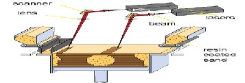
In this technique, developed by Helisys of Torrance, CA, layers of adhesive-coated sheet material are bonded together to form a prototype. The original material consists of paper laminated with heat-activated glue and rolled up on spools.
3.2.3.2 Process Description
IJSER © 2013 http://www.ijser.org
International Journal of Scientific & Engineering Research, Volume 4, Issue 7, July-2013 477
ISSN 2229-5518
Profiles of object cross sections are cut from paper or other web material using a laser. A focused laser cuts the outline of the first layer into the paper and then cross-hatches the excess area (the negative space in the prototype). The paper is unwound from a feed roll onto
the stack and first bonded to the previous layer using a heated (laminating) roller (Figure 3.3), which melts a plastic coating on the bottom side of the paper. The profiles are then traced by an optics system that is mounted to an X-Y stage. After cutting of the layer is complete, excess paper is
cut away to separate the layer from the web. Waste paper is wound on a take-up roll [11].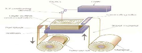
3.2.4. Ink-Jet Printing
Fig. 3.3: Laminated object manufacturing
3.2.4.1 Principle of Operation
This technology is also called Three Dimensional Printing (3DP). Actually, there is a broad range of diverse technologies that fall into the ink-jet printing category, but all rely on squirting a build material in a liquid or melted state, which cools or otherwise hardens to form a solid on impact.
3.2.4.2 Process Description
Solids cape, Inc.'s inkjet method (Thermal Phase Change Inkjets) uses a single jet each for a plastic build material and a wax-like support material, which are held in a melted liquid state in reservoirs (see Figure 3.4). The liquids are fed to individual jetting heads which squirt tiny droplets of the materials as they are moved in X-Y fashion in the required pattern to form a layer of the object [12].
The materials harden by rapidly dropping in temperature as they are deposited. After an entire layer of the object is formed by jetting, a milling head is passed over the layer to make it a uniform thickness. Particles are vacuumed away as the milling head cuts and are captured in a filter. The process is repeated to form the entire object. After the object is completed, the wax support material is either melted or dissolved away [13].
Fig. 3.4: Schematic diagram of Ink-jet printing technology
3.2.5 Laser Engineered Net Shaping (Lens)
Laser Engineered Net Shaping (LENS) is a technology that is gaining in importance and in early stages of commercialization. A high power laser is used to melt metal powder supplied coaxially to the focus of the laser beam through a deposition head (Figure 3.5). The laser beam typically travels through the centre of the head and is focused to a small spot by one or more lenses. The XY table is moved in raster fashion to fabricate each layer of the object. The head is moved up vertically as each layer is completed [14]. Metal powders are delivered and distributed around the circumference of the head either by gravity, or by using a pressurized carrier gas. An inert shroud Gas is often used to shield the melt pool from atmospheric oxygen for better control of properties, and to promote layer to layer adhesion by providing better surface wetting [14].
Fig. 3.5: Schematic diagram of Laser Engineered Net Shaping
IJSER © 2013 http://www.ijser.org
International Journal of Scientific & Engineering Research, Volume 4, Issue 7, July-2013 478
ISSN 2229-5518
A variety of materials can be used such as stainless steel, Inconel, copper, aluminium etc. Of particular interest are reactive materials such as titanium. Materials composition can be changed dynamically and continuously, leading to objects with properties that might be mutually exclusive using classical fabrication methods.
3.2.6 Liquid Metal Jet Printing (Lmjp)
The Liquid Metal Jet Printing (LMJP) is a revolutionary process technology in additive solid freeform manufacturing process. It can build mechanical parts and electronic interconnects in an additive manner. Unlike spray forming, LMJP is similar to ink jet printing where every individual molten droplet is controlled and printed to specific location. By changing the orifice size, the system will dispense molten spheres of metal with diameters from 100 to 1000 microns [14].
At the moment research work is focused on development of an aluminium-printing device for rapid prototyping of near net shaped mechanical
parts. Previous research work has included metal ball generation and capture, solder masks, and jetting copper for printing circuits [14].
3.2.7 Design-Controlled Automated Fabrication (Descaf)
The Design-Controlled Automated Fabrication (DESCAF) process builds prototypes a layer at a time by exposing liquid polymer to ultraviolet light through a photo mask. An entire layer is solidified simultaneously. The SOMOS Solid Imaging System is similar to SLA but differs in the photopolymer used and the laser system [14]. The material is a white, low shrinkage, proprietary resin with properties similar to silicon rubber. This material is claimed to have high photo speed, low shrinkage and war page, wide exposure latitude, flexible and homogeneous photo formed parts, and good layer-to-layer adhesion. The SOMOS system employs an argon-ion laser with high precision scanning in a raster pattern and high-speed beam modulation [14]. The Solid Creation System (SCS) uses similar technology used in Stereo lithography, but has the ability to build larger parts. The largest system has a build area of 40x32x20 inches.
The RP process evolution is compared in the table (4.1) bellow
Technology >> | Stereo lithography | Wide Area Inkjet | Selective Laser Sintering | Fused Deposition Modeling | Single Jet Inkjet | Three Dimensional Printing | Laminated Object Manufacturing |
Representative Vendor >> | 3D Systems | Stratasys | Solids cape | Z Corp. | Cubic Technologies | ||
General Qualitative Features | |||||||
Maximum Part Size (inches) | 20x22x22 | 12x10x10 | 17x15x20 | 24x20x24 | 12x8x10 | 20x22x18 | 30x20x20 |
Accuracy | very good | Good | Good | Fair | Excellent | Fair | Fair |
Surface Finish | Very good | fair | Fair | fair | Excellent | fair | Fair to poor (depending on Application) |
Speed | Average | Good | Fair | Poor | Poor | Excellent | good |
Strengths | market leader, large part size, accuracy, wide product line | market leader, office okay, | market leader, accuracy, materials, | office okay, price, materials, | accuracy, finish, office okay, | speed, office okay, price, colour, price | large part size, good for large castings, material cost |
Weaknesses | post processing, messy liquids | size and weight, fragile parts, limited materials, part size | size and weight, system price, surface finish | speed | speed, limited materials, part size | limited materials, fragile parts, finish | part stability, smoke finish and accuracy |
System Price | $75-800K | $50K | $300K | $30-300K | $70K- 80K | $30K-70K | $120-240K |
Material Costs $/pound |
Table 4.1: Comparison of important commercial rapid prototyping processes.
The following material used in the RP.
IJSER © 2013 http://www.ijser.org
International Journal of Scientific & Engineering Research, Volume 4, Issue 7, July-2013 479
ISSN 2229-5518
a) Plastics account for the preponderance of materials used in rapid prototyping systems. While in some cases, the plastics have the same name and chemical composition as familiar, home-grown materials such as nylon or ABS, there are substantial differences in what comes out of an RP system compared to the results from machining or injection moulding the same materials [10].
b) photopolymers are not exactly thermoplastics. The chemistry of photopolymers is very rich, however, and these materials are improving at a rapid pace [11]. Photopolymers that imitate polypropylene, ABS, polyethylene and a number of other plastics are available, as well as specialty materials for optical, medical and other applications.
Inkjet systems also output plastic parts. MultiJet Modeling (MJM) offers a soft, thermoplastic material which is essentially a hot melt adhesive. Other inkjets offer polyester or wax-like materials.
c) Metals: Commercially available choices are extremely limited for the direct fabrication of metal parts by rapid prototyping. For the most part today, metal parts made by rapid prototyping processes are being used to make injection moulds. RP technology can offer great time and monetary savings, as well as provide functionality, which would be impossible to obtain otherwise [14].
Laser engineered net shaping (LENS) and related processes offer the direct fabrication of fully dense steel parts. Final machining is necessary before parts can be used.
d) Ceramics parts can be acquired from a limited number of commercial sources and a few university labs. Paper has been the material most closely associated with laminated object manufacturing (LOM). Several companies provide systems that fabricate paper parts. One advantage is that the material is very inexpensive, but paper parts are not very stable. Paper parts have the look and feel of wood and are often used as sand casting patterns [15].
e) Plaster and starch parts are available from three dimensional printing (3DP) machines made by Z Corp. These are also inexpensive material but require some care in handling and must usually be infiltrated to make them durable.
f) Foundry sand parts can be fabricated using selective laser sintering (SLS) and also by a process from Generis GmbH (Germany) that is similar to three dimensional printing (3DP). This machine is most appropriate for making very large parts [16].
Rapid prototyping is widely used in the automotive, aerospace, medical, and consumer products industries. Although the possible applications are virtually limitless, nearly all fall into one of the following categories: prototyping, rapid tooling, or rapid manufacturing.
Rapid Tooling: A much-anticipated application of rapid prototyping is rapid tooling, the automatic fabrication of production quality machine tools. Rapid tooling can be divided into two categories, indirect and direct [17].
Indirect Tooling: RP parts are used as patterns for making moulds and dies. RP models can be indirectly used in a number of
manufacturing processes:
Vacuum Casting, Sand Casting, Investment Casting, Injection moulding.
Direct Tooling: To directly make hard tooling from CAD data is the one of most important for rapid tooling. Realization of this objective is still several years away.
Laser-Engineered Net Shaping (LENS), Rapid Tool, Direct AIM (ACES Injection Moulding), LOMComposite, Sand Moulding
Rapid Manufacturing: A natural extension of RP is rapid manufacturing (RM), the automated production of saleable products directly from CAD data [17]. RM will never completely replace other manufacturing techniques, especially in large production runs where mass-production is more economical [18].
RPT in Medical Applications: Applying RPT in the medicine is a new and exciting field. Many applications have become possible due to the convergence of three distinct technologies, namely Medical Imaging, Computer Graphics and CAD, and RPT [19] Computer-Assisted Tomography (CT) and Magnetic Resonance Imaging (MRI) provide highresolution images of internal structures of the human body, e.g. bone structures and organs.
This paper provides an overview of RP Technology in brief and emphasizes on their ability to shorten the product design and development process and detail of few important processes is given. The RP technologies provide the freeform fabrication of the complex geometry directly from their CAD models automatically.
The future looks very promising for rapid prototyping. The benefits for most applications far outweigh the disadvantages especially when they
are used in the correct situation. The price and size are rapidly falling to the point where they will soon be commonplace in any manufacturing company.
[1]. J.P. Kruth. Material In cress Manufacturing by Rapid Prototyping Techniques. CIRP Annals Manufacturing Technology, Volume 40, Issue 2, 1991, Pages 603-614.
[2]. R. Ippolito, L. Iuliano, A. Gatto. Benchmarking of Rapid Prototyping Techniques in Terms of Dimensional Accuracy and Surface
Finish.CIRP Annals - Manufacturing Technology, Volume 44,Issue 1, 1995, Pages 157-160
[3]. Chua, C.K., Leong, K.F. (2000) Rapid Prototyping: Principles and Applications in Manufacturing, World Scientific.
[4]. Pandey, P.M., Reddy, N.V., Dhande, S.G. (2003b) Real Time Adaptive Slicing for Fused Deposition Modelling, International Journal of Machine Tools and Manufacture, 43(1), pp 61-71.
[5]. Gebhardt, A., (2003) Rapid Prototyping, Hanser Gardner Publications, Inc., Cincinnati.
[6]. Richard Bibb, John Winder. A review of the issues surrounding three-dimensional computed tomography for medical modelling using rapid prototyping techniques. Radiography, Volume 16, Issue 1, February 2010, Pages 78-83.
IJSER © 2013 http://www.ijser.org
International Journal of Scientific & Engineering Research, Volume 4, Issue 7, July-2013 480
ISSN 2229-5518
[7]. Yongnian Yan, Shengjie Li, Renji Zhang, Feng Lin, Rendong Wu, Qingping Lu, Zhuo Xiong, Xiaohong Wang. Rapid Prototyping and Manufacturing Technology: Principle, Representative Technics, Applications, and Development Trends. Tsinghua Science & Technology, Volume 14, Supplement 1, June 2009, Pages 1-12.
[8]. S. Kumar, J.-P. Kruth. Composites by rapid prototyping technology. Materials & Design, Volume 31, Issue 2, February 2010, Pages
850-856.
[9]. F. Xu, Y. S. Wong, H. T. Loh. Toward generic models for comparative evaluation and process selection in rapid prototyping and manufacturing. Journal of Manufacturing Systems, Volume 19, Issue 5, 2001, Pages 283-296.
[10]. Manufacturing Engineering and Engineering, 4th edition, Serope Kalpakjian & Steven R Schmid, Prentice Hall International, 2000. [11]. Bahattin Koc, Yuan-Shin Lee. Non-uniform offsetting and hollowing objects by using biarcs fitting for rapid prototyping processes.
Computers in Industry, Volume 47, Issue 1, January 2002, Pages 1-23.
[12]. M. Greul, T. Pintat, M. Greulich. Rapid prototyping of functional metallic parts. Computers in Industry, Volume 28, Issue 1,
December 1995, Pages 23-28.
[13]. R.F. Hamade, F. Zeineddine, B. Akle, A. Smaili. Modelangelo: a subtractive 5-axis robotic arm for rapid prototyping. Robotics and
Computer-Integrated Manufacturing, Volume 21, Issue 2, April 2005, Pages 133-144.
[14]. Xue Yan, P Gu. A review of rapid prototyping technologies and systems. Computer-Aided Design, Volume 28, Issue 4, April 1996,
Pages 307-318.
[15]. Gan G. K. Jacob, Chua Chee Kai, Tong Mei. Development of a new rapid prototyping interface. Computers in Industry, Volume 39, Issue 1, June 1999, Pages 61-70.
[16]. Nold, J. Zeiner, T. Assion, R. Clasen. Electrophoretic deposition as rapid prototyping method. Journal of the European Ceramic
Society, Volume 30, Issue 5, March 2010, Pages 1163-1170.
[17]. R.F. Louh, Yiwen Ku, Irene Tsai Rapid Prototyping: Fast Track to Product Realization, Society of Mechanical Engineers, 1994.
Rapid prototyping technique for ceramic minidevices containing internal channels with asymmetrical contour. Journal of the
European Ceramic Society, Volume 30, Issue 14, October 2010, Pages 2841-2847.
[18]. Garrett E. Ryan, Abhay S. Pandit, Dimitrios P. Apatsidis. Porous titanium scaffolds fabricated using a rapid prototyping and powder metallurgy technique. Biomaterials, Volume 29, Issue 27, September 2008, Pages 3625-3635.
[19]. J.-P. Kruth, M.C. Leu, T. Nakagawa. Progress in Additive Manufacturing and Rapid Prototyping. CIRP Annals - Manufacturing
Technology, Volume 47, Issue 2, 1998, Pages 525-540.
IJSER © 2013 http://www.ijser.org