Consider the diagram given below for the gait pattern of a normal individual :
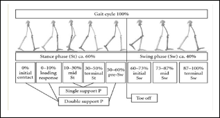
Fig.1 Gait Cycle
International Journal of Scientific & Engineering Research, Volume 6, Issue 5, May-2015 1435
ISSN 2229-5518
Powered Foot Ankle Prosthesis
Neethu Rajan, Swagatika Mishra, Abhishek Patil & Jyothi Warrier
Abstract— A powered foot ankle prosthesis is a lower body extremity prosthesis, which is an artificial extension that replaces the part missing below the knee. It is part of the field of biomechatronics, the science of fusing mechanical devices with human muscle, skeleton, and nervous systems; to assist or enhance motor control lost by trauma, disease, or defect. This research paper focuses on the transtibial condition and the prosthetic device which acts as an aid to the individuals affected by such conditions. The paper mainly aims at creating a visual record to reeducate an amputee on the normal gait pattern. The main components of the prosthetic device includes the accelerometer sensor, the pic microcontroller and the dc motor. The accelerometer sensor should be placed at the normal foot of the individual and for different standard gait patterns like heel strike, foot flat, heel off and acceleration, the accelerometer measures different values for all the three axes. These values so sensed by the sensor will be read by the microcontroller and the microcontroller will be programmed in such a manner that for specific values, the motor will provide either a clockwise or an anticlockwise motion as per the requirement. Thus both the dorsiflexion and plantar flexion of the prosthetic foot is made possible by the motor whose movement will be controlled by the microcontroller. Thus a co-ordinated working of the sensor, microcontroller and the motor will provide the exact gait pattern for the transtibial prosthetic device and its visual record will help the patient to provide a better understanding of gait which he has to follow while using his prosthetic device.
Index Terms— Accelerometer, Dorsiflexion, Motor, Motor Driver, Plantar Flexion, Stance phase, Swing phase, Transtibial
—————————— ——————————
ROSTHESIS is an artificial extension that replaces a missing body part, which may be lost through trauma, disease, or congenital conditions[1]. Lower extremity prostheses provide replacements at varying levels of amputation. These include hip disarticulation, transfemoral prosthesis, knee disarticulation, transtibial prosthesis, Symes foot, partial foot prosthesis and toe fillers. The two main subcategories of lower extremity prosthetic devices are transtibial (any amputation transecting the tibia bone or a congenital anomaly resulting in a tibial deficiency) and transfemoral (any amputation transecting the femur bone or a congenital anomaly resulting in a femoral deficiency). A transtibial prosthesis is an artificial limb that replaces a leg missing below the knee. Transtibial amputees are usually able to regain normal movement more readily than someone with a transfemoral amputation, due in large part to retaining the knee, which allows for easier movement[1].In the prosthetic industry a transtibial prosthetic leg is often referred to as a
"BK" or below the knee prosthesis.
The main objective is to make a powered ankle–foot prosthesis
capable of mimicking human ankle dynamics in level-ground
walking and to aid in amputee ambulation[2].The project
mainly aims at creating a visual record capable of re educating
an amputee for gait.
————————————————
• Jyothi Warrier and Abhishek Patil are currently working in Department of Bio-Medical Engineering, MGM’s College of Engineering & Technology, Kamothe, Navi-Mumbai – 410209.
• Swagatika Mishra is currently working in Department of Prosthetic and
Orthotic, MGM Medical College and Hospital, Kamothe, Navi-Mumbai –
410209.
The analysis on the human gait cycle is an important criteria which helps to study the gait of a normal and a transtibial condition. The standard gait cycle comprises of the stance phase(60% of gait cycle ) and swing phase(40% of gait cycle). Out of the different gait patterns, efforts have been made to enact the patterns like heel strike, foot flat and heel off in the stance phase and acceleration in the swing phase.
Consider the diagram given below for the gait pattern of a normal individual :
Fig.1 Gait Cycle
The block diagram of the Powered foot ankle prosthesis comprises of the following modules mentioned below:
• Power Supply
• Accelerometer Sensor(ADXL335)
• Microcontroller(PIC 16F877A)
• Motor Driver(L293d)
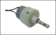
• DC geared motor( 12V)
IJSER © 2015 http://www.ijser.org
International Journal of Scientific & Engineering Research, Volume 6, Issue 5, May-2015 1436
ISSN 2229-5518
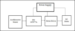
Fig.2 Block Diagram
The sensor used is the tri axial accelerometer sensor which detects its own acceleration and gives the output values. The values so measured by the sensor will be read by the microcontroller. The microcontroller will be programmed in such a manner that for different values of acceleration, the different foot movements like dorsiflexion and plantar flexion will be performed. The different foot positions will be adjusted by the motor whose movement will be controlled by the microcontroller. Thus a co-ordinated working of the sensor, microcontroller and the motor will provide a better gait pattern for the transtibial patient. The prosthetic device should also be able to mimic the two important parameters i.e the standard foot Centre of pressure (COP) and force graph of a normal subject in a transtibial case.
of ±3 g minimum. It can measure the static acceleration of
gravity in tilt-sensing applications as well as dynamic
acceleration resulting from motion, shock, or vibration. The ADXL335 uses a single structure for sensing the X, Y, and Z axes. The accelerometer sensor has to be attached to the normal foot of the individual and it gives the output values for all three axes for different foot gait patterns which are then fed to the controller.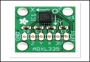
Fig.3 Accelerometer Sensor ADXL335
Controller. The controller used is PIC16f877A which is a 40pin IC. It accepts the ADC values from the accelerometer sensor and it enables the motor to perform the required motions as per the set values. The PIC microcontroller has certain special microcontroller features like inbuilt ADC, High-Performance RISC CPU and CMOS technology which make it more preferable over other controllers.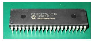
Fig.4 PIC16F877A Microcontroller
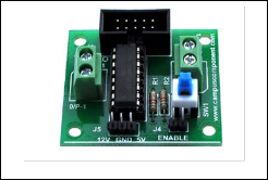
Fig.5 Motor Driver L293D
IJSER © 2015 http://www.ijser.org
International Journal of Scientific & Engineering Research, Volume 6, Issue 5, May-2015 1437
ISSN 2229-5518
Fig.6 DC gear motor
TABLE 1
It can be concluded that better transtibial gait patterns can be acquired by considering the visual record, which will educate the transtibial patients to get a clear image of the gait pattern their prosthetic device should carry out. The prosthetic device provides the standard gait patterns like heel strike, foot flat and heel off for corresponding values sensed by the accelerometer sensor. Thus, the basic idea of providing the movements of dorsiflexion and plantar flexion which is normally absent in a transtibial subject has been successfully carried out by the active coordination between the sensor, microcontroller and the motor.
ACCELEROMETER ADC READING OUTPUT
Accelerometer X-axis value | Accelerometer Y-axis value | Accelerometer Z-axis value | Standard Gait Pattern |
ADC1 > 105 | ADC2 > 90 | ADC3 > 80 | Heel Strike |
ADC1 > 103 | ADC2>85 | ADC3>93 | Foot Flat |
ADC1 > 95 | ADC2 > 90 | ADC3 > 100 | Heel off |
ADC1 > 76 | ADC1 > 85 | ADC1 > 117 | Acceleration |
• Initially, the accelerometer sensor should be placed on the anterior tibial shin, at a distance of 4” from the Mid-Patella Tendon on the normal foot and the amputee should be allowed to visualize the gait pattern followed by the prosthetic foot, with the changing sensor positions.
• This enables the amputee to learn the gait pattern that he should make possible, when the prosthetic limb is attached to his body.
• After educating the patient likewise, in the later
stages, the accelerometer sensor should be placed in
the prosthetic device itself and the patient should try to carry out the motions which he had learned in the visual training.
• Thus, the patient will enact the same type of gait
pattern he has seen in the visual record and it will
help him in attaining the standard gait patterns with the aid of the coordinated working of all the electronic mechanisms built in the prosthetic device.
The authors are thankful to Dr K G Narayankhedkar, Director General, MGM group of Engineering Colleges, Dr S K Narayankhedkar, Principal MGM College of Engineering and Technology, Navi Mumbai, Dr G D Jindal, Head, Bio-Medical Engineering Department MGMCET for their encouragement right through this development. Authors are also thankful to
to all nonteaching staff of the department, i.e. Shri Suryapal Prajapati, Shri Nazim Momin and Shri B V Gaikwad; and students of department for their continuous help.
[1] Dr. Grant McGimpsey and Terry C. Bradford, Limb Prosthetics Services and Devices, Bioengineering Institute Center for Neuroprosthetics Worcester Polytechnic Institution
[2] Samuel K. Au, Jeff Weber, and Hugh Herr, Member,
IEEE, Powered Ankle–Foot Prosthesis Improves
Walking Metabolic Economy
[3] Andre Bahler, The Biomechanics of the Foot, Clinical
Prosthetics and Orthotics, Vol.10, No.1,pp.8-14©1986
The American Academy of Prosthetics and Orthotics.
IJSER © 2015 http://www.ijser.org