The research paper published by IJSER journal is about Performance Analysis of a Vortex Tube by using Compressed Air 1
ISSN 2229-5518
Performance Analysis of a Vortex Tube by using
Compressed Air
Ratnesh Sahu, Rohit Bhadoria, Deepak Patel
Abstract-In present, the first and foremost important quality of any research or development is its eco friendly nature, by the virtue of which it fulfills our basic needs without any harm to the nature. Today, environment safety has become an important aspect of the indu stries and people in common. This paper aims at increase in efficiency of one such eco friendly system named vortex tube used for i ndustrial spot cooling and process cooling needs, such as Spot cooling, Weld cooling, Plastic slitting, Extrusion cooling, Foodstuffs coolin g etc. The commonly used cooling systems use the gas and liquids which either deplete the ozone layer or contribute in the global warming in the same as CO2 does. Efforts have been made to include various aspects to get the maximum output in terms of C.O.P. (COEFICIENT OF PERFORMANCE) and knowledge about the vortex tube. The report includes detailed explanation of worki ng and construction of a vortex tube with experimental results for a series of different physical, thermal and mechanical conditions. This paper summarizes a nalysis of cooling and heating effect, temperature difference and C.O.P. with different working conditions and constructional features. This paper also has the tabulated data with experimental values.
Index Term-Coefficient of Performance, Compressed air , Hot & Cold air.
—————————— ——————————
made on the basis of some series of different-different
mechanical, physical and constructional features and the
performance of tube depends upon:
The Vortex Tube is an effective and low cost solution to a
wide variety of industrial spot cooling and process cooling needs. We can say Vortex tube is a device which produces cooling at one end and heating at the other end simultaneously. The general name of vortex tube is cooling tube also, which instantaneously create streams of high and low temperature with respect to the temperature of the air which is used as a feed. The highly compressed air is forcing through a generation chamber, and by the virtue of high pressure and limited volume the pressure head of feeding air is get converted into the kinetic head which generates the centrifugal spin of air along the inner walls of the tube. It is evident that the cooling unit part does not incorporate any moving part if high pressure air is available. It has no moving parts; pressurized gas is injected tangentially into a swirl chamber and accelerates to a high rate of rotations. The Compressed air which is supplied to the vortex tube and passes through nozzles that are tangent to an internal counter bore. These nozzles set the air in a vortex motion. This spinning stream of air turns
90° and passes down the hot tube in the form of a spinning
shell, similar to a tornado Due to the conical nozzle at the
end of the tube, only the outer shell of the compressed gas is allowed to escape at that end. The remainder of the gas is forced to return in an inner vortex of reduced diameter within the outer vortex. A percentage of the hot, high-speed air is permitted to exit at the control valve. The remainder of the (now slower) air stream is forced to counter flow up through the center of the high-speed air stream, giving up heat, through the center of the generation chamber finally exiting through the opposite end as extremely cold air. For the performance analysis of this kind of vortex tube is being
(a) Air parameter
(b) Tube parameter
The controlling process of volume and temperature of cold air produced by a Vortex Tube was done by the valve in the hot air exhaust. This volume (Cold Fraction) is the percent of total input air released through the cold exhaust. For example, if the total volume of compressed air input is 15SCFM and the Cold Fraction is 70%, then 10.5
SCFM exits the cold end and 4.5 SCFM exits the hot end. A
high Cold Fraction. (i.e., more than 50% or the input air
exiting the cold air exhaust), produces the maximum
efficiency -- the greatest BTUH output. The maximum
efficiency condition occurs at Cold Fractions of 60% to 70%, where the amount of air released at the cold exhaust and the temperature drop are optimized. Some industrial operations like cooling machining operations, electronic
controls, liquid baths, and workers will require high Cold
Fractions for maximum refrigeration.
The fluid which rotates in a vortex along the axis may touch the high speed up to 1,000,000 RPM. And due to this Vortex tubes are able to generate temperatures down to
100°F below inlet air temperature.
The vortex tube was invented quite by accident in
1928. George Ranque, a French physics student, was
experimenting with a vortex-type pump he had developed when he noticed warm air exhausting from one end, and
IJSER © 2012 http://www.ijser.org
The research paper published by IJSER journal is about Performance Analysis of a Vortex Tube by using Compressed Air 2
ISSN 2229-5518
cold air from the other. Ranque soon forgot about his pump and started a small firm to exploit the commercial potential for this strange device that produced hot and cold air with no moving parts. However, it soon failed and the vortex tube slipped into obscurity until 1945 when Rudolph Hilsch, a German physicist, published a widely read scientific paper on the device.
Much earlier, the great nineteenth century physicist, James Clerk Maxwell postulated that since heat involves the movement of molecules, we might someday be able to get hot and cold air from the same device with the help of a "friendly little demon" who would sort out and separate the hot and cold molecules of air.
Thus, the vortex tube has been variously known as the "Ranque Vortex Tube", the "Hilsch Tube", the "Ranque-Hilsch Tube", and "Maxwell’s Demon". By any name, it has in recent years gained acceptance as a simple, reliable and low cost answer to a wide variety of industrial spot cooling problems.
Some important historical events which are directly related with development of vortex tube are as:
![]() The separation of gas mixtures, oxygen and nitrogen, carbon dioxide and helium, carbon dioxide and air with the vortex tube (VT) was reported in 1967 by Linderstrom-Lang and in 1977 by J. Marshall.
The separation of gas mixtures, oxygen and nitrogen, carbon dioxide and helium, carbon dioxide and air with the vortex tube (VT) was reported in 1967 by Linderstrom-Lang and in 1977 by J. Marshall.
![]() In 1979 steam was used as working medium by
In 1979 steam was used as working medium by
Takahama.
![]() In 1979, two-phase propane was used as the working medium by Collins.
In 1979, two-phase propane was used as the working medium by Collins.
![]() In 1988 Balmer applied liquid water as the working medium. It was found that when the inlet Pressure is high, for instance 20-50 bar, the energy separation effect still exists. So it proves that the energy separation process exists in incompressible (liquids) vortex flow as well.
In 1988 Balmer applied liquid water as the working medium. It was found that when the inlet Pressure is high, for instance 20-50 bar, the energy separation effect still exists. So it proves that the energy separation process exists in incompressible (liquids) vortex flow as well.
![]() In 2004, natural gas was used as working medium and with the VT natural gas was liquefied by Nikolay Poshernev.
In 2004, natural gas was used as working medium and with the VT natural gas was liquefied by Nikolay Poshernev.
![]() Timothy of I.I.T. Mumbai obtained a drop of 75°C with inlet air at 8 bar and 300 K. Hing and Naganagoudar of IIT Mumbai were able to increase a drop to 83°C.
Timothy of I.I.T. Mumbai obtained a drop of 75°C with inlet air at 8 bar and 300 K. Hing and Naganagoudar of IIT Mumbai were able to increase a drop to 83°C.
The procedure for analysis which have adopted is as follows: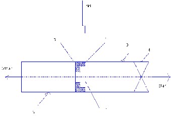
The layout of a vortex tube is given in fig. it consist of following parts. :
1. Nozzle
2. Diaphragm
3. Valve
4. Hot air side
5. Cold air side
6. Chamber
Compressed air is admitted to the vortex tube through (1) in the nozzle the air acquires high velocity and enters the chamber. (2) Tangentially where it forms a vortex. (3) This vortex is formed because of the particular shape of the chamber. The vortex travels through the hot side (4) of the tube through the diaphragm. (5) Part of this air flows back towards the diaphragm (2). It then leaves the tube through the diaphragm (2) and the cold end (3). The hot air passes through the valve. By adjusting the valve opening the quantity of cold air and the temperature drop can be varied. The maximum drop is obtained for a particular opening of the valve. A decrease in temperature drop will result by reducing the valve opening below this opening.
For the analysis of vortex tube following procedure has adopted. For the series of observation we have to feed
IJSER © 2012 http://www.ijser.org
The research paper published by IJSER journal is about Performance Analysis of a Vortex Tube by using Compressed Air 3
ISSN 2229-5518
air at different-different pressure and temperature that is on different thermodynamic conditions, then apply the formula and find out the value of critical C.O.P.as our aim of analysis.
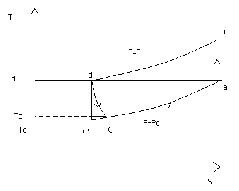
Fig. Vortex tube cycle on T-S diagram
Air is admitted to the compressor at atmospheric temperature Ta and pressure Pa (point A). This air is compressed adiabatically to pressure Pi. This air is then cooled at constant pressure Pi to the atmospheric temperature by water cooling. It then enters the vortex tube where it is separated in two streams (hot & cold streams).
Area = ∏/4*D2
Discharge (q) =A*V
Mass flow rate (m) = q* ρ
Cooling effect (q) = mCp∆T
Work done by compressor (W) = ( n*3600)/( t*200)
kW
Actual COP = actual cooling effect in vortex tube/ Work done by air compressor = Q/W
Temperature difference (∆T)
Time for total number of revolutions (t)
Total number of revolution of energy meter (n)
Velocity(v)
Internal diameter of tube = 5.608 cm
Diameter of diaphragm = 2.0 cm
Pitch of Handy knob valve = 2mm
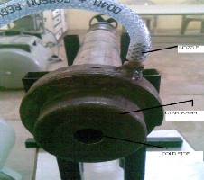
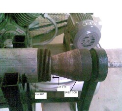
Fig. Parts of vortex tube
Fig. Handy Knob
Nozzle ¼ inch
Tube of length 40 cm
External diameter of tube = 6.1 cm
IJSER © 2012 http://www.ijser.org
The research paper published by IJSER journal is about Performance Analysis of a Vortex Tube by using Compressed Air 4
ISSN 2229-5518
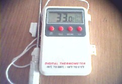
Temperature range: -50°c to 300°c
Unit rpm: 720rpm
Tank capacity: 160 liter
Number of stages: two
Cylinder cooling: air cooling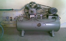
Display: 10mm LCD
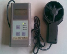
Operating temperature: 0 to 50
Operating humidity: less than 80% RH
Range: 0.4 to 30 m/s
1.4 to 108 Km/hr
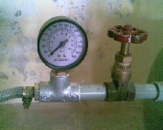
Pressure range (10-3.5bar)
Temperature difference (∆T) = 13.7°c
Area = ∏/4*D2 = ∏/4*0.0202 = 3.142*10-4 m2
Velocity = 16.7 m/s
Discharge (q) =A*V=3.142*10-4 * 16.7=0.00524 m3/s
Mass flow rate (m) = q* ρ=.00524*1.207=0.0063 Kg/s
Cooling effect (q) =mCp∆T= 0.0063*1.005*13.7=0.0867
KW
Total number of revolution of energy meter (n) =41
Time for total number of revolutions (t) = 574.2 sec.
Work done by compressor (W) = (n*3600)/ (t*200)
kW
= (41*3600)/ (574.2*200) = 1.28 KW
Actual COP = actual cooling effect in vortex tube/ Work done by air compressor = Q/W
= 0 .0867/1.28 = 0.068
Pressure range (9-3.5bar)
Temperature difference (∆T) =15.1°c
Area = ∏/4*D2 = ∏/4*0.0202 = 3.142*10-4 m2
Velocity =12.6 m/s
Discharge (q) =A*V= 0.0039m3/s
Mass flow rate (m) = q* ρ=0.0047Kg/s
Cooling effect (q) = mCp∆T= 0.071KW
Total number of revolution of energy meter (n) =40
Time for total number of revolutions (t) = 568.2sec.
Work done by compressor (W) =(n*3600)/( t*200) kW
=1.267
Actual COP = actual cooling effect in vortex tube/
Work done by air compressor
= Q/W = 0.057
IJSER © 2012 http://www.ijser.org
The research paper published by IJSER journal is about Performance Analysis of a Vortex Tube by using Compressed Air 5
ISSN 2229-5518
Vortex tube is used for utilizing the waste compressed air which is produced in various industrial applications. For this tube if we use a separate compressor then the complete process is not so efficient, just because of
low C.O.P.
Ti = inlet air temperature of vortex tube.
Tc = outlet air temperature of vortex tube at the cold side.
Th = outlet air temperature of vortex tube at the hot side.
Table 1: For fully closed handy knob.
Pressure Range (in bar) | Inlet temp. (Ti) (in °c) | Cold side Temp. (Tc) (in °c) | Hot side Temp. (Th) (in °c) | Temperature difference (in °c) | Velocity (in m/s) | Number of revolution of Energy meter(n) | Time (in minute) | COP |
10-3.5 | 28 | 14.3 | 30 | 13.7 | 16.7 | 41 | 9.57 | 0.068 |
9-3.5 | 28 | 16 | 30 | 12 | 15.3 | 40 | 9.47 | 0.055 |
8-3.5 | 30 | 19.5 | 31 | 10.5 | 17.6 | 37 | 8.67 | 0.055 |
7-3.5 | 30 | 20.5 | 31 | 9.5 | 16.8 | 31 | 7.15 | 0.047 |
6-3.5 | 31 | 22 | 31 | 9 | 16.9 | 27 | 6.16 | 0.044 |
5-3.5 | 31 | 23.5 | 31 | 7.5 | 16.8 | 20 | 4.35 | 0.035 |
Table 2: For partially open handy knob:-
Pressure Range (in bar) | Inlet temp. (Ti) (in°c) | Cold side Temp. (Tc) (in °c) | Hot side Temp. (Th) (in °c) | Temperature difference (in °c) | Velocity (in m/s) | Number of revolution of energy meter | Time (in minute) | COP |
10-3.5 | 30 | 15.3 | 31 | 14.7 | 12.5 | 41 | 9.57 | 0.054 |
9-3.5 | 31 | 15.9 | 31 | 15.1 | 12.6 | 40 | 9.47 | 0.057 |
8-3.5 | 32 | 18.8 | 32 | 13.2 | 12.1 | 37 | 8.67 | 0.048 |
7-3.5 | 32 | 21.3 | 32 | 10.7 | 12.2 | 31 | 7.15 | 0.038 |
IJSER © 2012 http://www.ijser.org
The research paper published by IJSER journal is about Performance Analysis of a Vortex Tube by using Compressed Air 6
ISSN 2229-5518
6-3.5 | 33 | 22.8 | 33 | 10.2 | 11 | 27 | 6.16 | 0.033 |
5-3.5 | 33 | 23.3 | 33 | 9.7 | 11.7 | 20 | 4.35 | 0.031 |

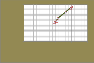
0.08
0.07
0.06
0.05
0.04
0.03
0.02
0.01
0
The current phase of our research project described in this paper is to fabricated the vortex tube with the easily available resources, from the study done so far on vortex tube we already know that its C.O.P. is very less and we wanted to study it practically. Vortex tube also involves second law of thermodynamics which shows the degradation of energy from a higher quality and quantity to lower quality and quantity. The study is successfully made by using a separate compressor. This compressed air for the practical application should be taken from other resources where it is going waste. Utilizing waste is always a warming issue for the industries. We hope that this study will play an important role in the future scope of this project.
0 5 10 15
0.06
0.05
0.04
0.03
0.02
0.01
0
0 5 10 15 20
[1] Piotr A. Domnski, David Yashar- “Performance of a Finned Tube Evaporator Optimized for Different Refrigerants and its Effects on System Efficiency”.
Elsevier journal (2009)
[2] S.S. Thipse, “Refrigeration & Air Conditioning”
Jaico publishing house; 2007.
[3] Prof. P.S. Desai, “Refrigeration & Air Conditioning”
Khanna publishers; 2004.
[4]Ratnesh Sahu-“Comparative analysis of Mint Gas with
refrigerant R-12 and R-134a”.
IJSER journal,2011
[5] Prof. U.S.P. Shet , Prof. T. Sundararajan and Prof. J.M .
Mallikarjuna “Refrigeration Cycle” IIT Madras.
IJSER © 2012 http://www.ijser.org
The research paper published by IJSER journal is about Performance Analysis of a Vortex Tube by using Compressed Air 7
ISSN 2229-5518
[6]Ratnesh Sahu- “Comparative analysis of Mint Gas with Commonly used Refrigerant”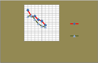
0.08
0.06
0.04
0.02
0
0 5 10
FULLY CLOSED
PARTIALLY OPEN
IJSER © 2012 http://www.ijser.org