
INTERNATIONAL JOURNAL OF SCIENTIFIC & ENGINEERING RESEARCH, VOLUME 4, ISSUE 6, MAY 2013
ISSN 2229-5518
1091
Performance Analysis of Modified Booth Multiplier with use of Various Adders
Ms. Jasbir Kaur, Mandeep Singh
Abstract—In this paper Modified Booth Multiplier (radix-4) implemented by various adder. Partial product generated by booth encoder is added by various adder techniques to compare the performance parameter of multiplier. Performance parameter like area, path d elay, fan out, speed of multiplier. Multiplication is an important fundamental function in arithmetic logic operation. Since, multiplication dominates the execution time of most DSP algorithms; therefore, high-speed multiplier is much desired. Multiplication time is still the dominant factor in determining the instruction cycle time of a DSP chip. With an ever-increasing quest for greater computing power on battery-operated mobile devices, design emphasis has shifted from optimizing conventional delay time area size to minimizing power dissipation while still maintaining the high performance. The three important considerations for VLSI design are Power, Area and Time delay.
Keywords—Modified Booth Multiplier, Booth Encoder, partial product, Full adder ,Ripple carry adder Look ahead adder, Carry select adder.
—————————— ——————————
ultipliers are key components of many high performance systems such as FIR filters microprocessors, digital signal processors, etc. The most important design challenges for multimedia and digital signal processing (DSP) applications, enhancing the processing performance and reducing the power dissipation, reduce the area ,increase the speed of the systems in which multipliers frequently dominate the system’s performance . The multipliers are the better option for high-speed data processing. Multiplication consists of three main steps 1. Recoding (generating the partial product) 2.reducing the partial product in two rows.3. Addition. Various algorithms proposed for multiplication are Booth Algorithm, Modified Booth Algorithm, Braun and Baugh-Wooley. In this paper, used of different adder (FA, RCA, CSLA, CLA) technique for enhancing the performance and reducing the area of Modified Booth Multiplier (MBM). MBM is reduced the no. of partial product by half using the Radix-4 Booth recoding. In past the multiplication process was implemented by sequence of addition, subtraction and shift operation .Multiplicand is added no. of times as that of no. of multiplier and result is product. Multiplier decomposes into two parts. First part is generating the partial product and second part is recoded and adds them. The multiplication principle is twofold i.e. evaluation of partial products and accumulation of the shifted partial products. It is performed by the successive additions of the columns of the shifted partial product
matrix..
————————————————
The ‘multiplier’ is successfully shifted and gates the appropriate bit of the ‘multiplicand’. They are then added using the different technique of adder to form the product bit for the particular form Fig 1 shows the structure of modified booth multiplier. Functionality of each block described.
Fig.1 Structure of Modified Booth Multiplier
For high-speed multiplication, the Modified Booth’s algorithm (MBA) Radix-4 [1] [2] is used. This type of multiplier operates much faster than an array multiplier for longer operands because its computation time is proportional to the logarithm of the word length of operands. It reduces the no. of partial product by half. Radix-4 algorithm reduces the area of and increase the
IJSER © 2013
INTERNATIONAL JOURNAL OF SCIENTIFIC & ENGINEERING RESEARCH, VOLUME 4, ISSUE 6, MAY 2013
ISSN 2229-5518
1092
speed of multiplier. The idea is that, instead of shifting and
adding for every column of the multiplier term and multiplying by 1 or 0, we only take every second column and multiply by ±1, ±2, or 0, to obtain the same results. Advantage of this method reduced the partial product by half [3], [4]. It recode the multiplier term. It recodes the block of three bits, such that each block overlaps the previous block by one bit. In starting grouping from LSB, it contains the two bit of the multiplier and one additional LSB bit of first block assumes to be ‘0’. Fig 2 shows the grouping of bits of the multiplier ‘B’ term for use of Booth Encoding. However, this cannot completely solve the problem due to the long critical path for multiplication [6], [7].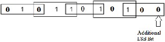
Fig.2 Grouping of bits from the multiplier term
Each block of multiplier ‘B’ is decoded to generate the partial product. According to the encoding of multiplier ‘B’, booth algorithm generates the following five signed digits -
2, -1, 0, 1, 2. Each encoded digit of the multiplier performs
the particular operation with multiplicand ‘A’ as shown in
the table below.
TABLE.1
BOOTH-4 ENCODING
Block(Multiplier bits) | Re-coded Digit | Operation on A(Multiplican d) |
000 | 0 | 0A |
001 | +1 | +1A |
010 | +1 | +1A |
011 | +2 | +2A |
100 | -2 | -2A |
101 | -1 | -1A |
110 | -1 | -1A |
111 | 0 | 0A |
Addition is a fundamental operation for any digital system, digital signal processing or control system. A fast and accurate operation of a digital system is greatly influenced by the performance of the resident adders. Adders are also
very important component in digital systems because of
their extensive use in other basic digital operations such as subtraction, multiplication and division. Hence, improving performance of the digital adder would greatly advance the execution of binary operations inside a circuit compromised of such blocks. The performance of a digital circuit block is gauged by analyzing its power dissipation, layout area and its operating speed.
Various adders implement on partial product which is generated by Booth Encoder process. Characteristic and performance of these adder are describe below
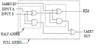
A full adder is a combinational circuit that performs the arithmetic sum of three bits: A, B and a carry in, C, from a previous addition, Fig. 3a. Also, as in the case of the half adder, the full adder produces the corresponding sum, S, and a carry out Co. Full adder may be designed by two half adders in series as shown below in Figure 3(b).
S = C ![]() (A
(A ![]() B)
B)
Co = AB + C (A![]() B)
B)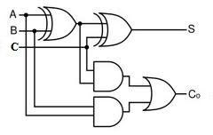
(a)
(b)
IJSER © 2013
INTERNATIONAL JOURNAL OF SCIENTIFIC & ENGINEERING RESEARCH, VOLUME 4, ISSUE 6, MAY 2013
ISSN 2229-5518
1093
Fig 3 (a) Full adder (b) Full adder using half adder
The ripple carry adder is constructed by cascading full adders (FA) blocks in series. One full adder is responsible for the addition of two binary digits at any stage of the ripple carry. The carryout of one stage is fed directly to the carry-in of the next stage. A number of full adders may be added to the ripple carry adder or ripple carry adders of different sizes may be cascaded in order to accommodate binary vector strings of larger sizes. For an n-bit parallel adder, it requires n computational elements (FA). Figure 4 shows an example of a parallel adder: a 4-bit ripple-carry adder. It is composed of four full adders. The augend’s bits of x are added to the addend bits of y respectfully of their binary position. Each bit addition creates a sum and a carry out. The carry out is then transmitted to the carry in of the next higher-order bit. The final result creates a sum of four bits plus a carry out (c4).
parallel adder. The CLA adder is one of the fastest schemes used for the addition of two numbers, since the delay to add two numbers depends on the logarithm of the size of the operands: ∆ ≈ log [N]. To be able to understand how the carry look-ahead adder works, we have to manipulate the Boolean expression dealing with the full adder. The Propagate P and generate G in a full-adder, is given as:
Pi = Ai ![]() Bi Carry propagate
Bi Carry propagate
Gi = Ai Bi Carry generate
Note that both propagate and generate signals depend only on the input bits. The new expressions for the output sum and the carryout are given by:![]()
Si = Pi Ci-1
Ci+1= Gi + Pi Ci
These equation show that carry signal generated in two cases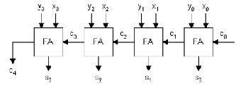
If both bits Ai and Bi are 1
If either Ai or Bi is 1 and the carry-in Ci is 1.
Carry look-ahead adder’s structure can be divided into three parts:
Fig 4 4-bit Ripple Carry Adder
Drawback of this adder is that the delay increases linearly with the bit length. Each full adder has to wait for the carry out of the previous stage to output steady-state result. Generally speaking, the worst-case delay of the RCA is when a carry signal transition ripples through all stages of adder chain from the least significant bit to the most significant bit, which is approximated by:
t= (n-1) tc + ts
Where tc is the delay through the carry stage of a full adder, and ts is the delay to compute the sum of the last stage. The delay of ripple carry adder is linearly proportional to n, the number of bits; therefore the performance of the RCA is limited when n grows bigger. The advantages of the RCA are lower power consumption as well as a compact layout giving smaller chip area.
Carry Look Ahead Adder (CLA) developed by Weinberger and Smith in 1958 [8], [9] to improvement in speed of
1) The propagate/generate generator Fig 5.
2) The sum generator Fig.6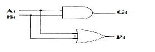
3) The carry generator Fig.7
Fig. 5 Propagate/generate Generator
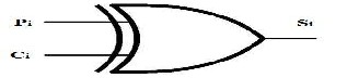
Fig 6 Sum Generator
Delay of CLA is not directly proportional to the size of the adder N, but to the number of levels used. Generally the number of look ahead levels for an N-bit adder is [log k N] where k+1 is the maximum number of inputs per gate. Since a k-bit group carry-look ahead adder introduces three gate delays per CLA level, and there are two additional gate delays: one for gi and pi, and other for the final sum si, CLA delay ∆ is:
IJSER © 2013
INTERNATIONAL JOURNAL OF SCIENTIFIC & ENGINEERING RESEARCH, VOLUME 4, ISSUE 6, MAY 2013
ISSN 2229-5518
1094
CLA log [N] 1) 1 4 log [N]
CLA is achieving lesser speed than expected, especially when compared to some techniques that consume less hardware for the implementation as shown in [10], [11]. The CLA has the fastest growing area and power requirements with respect to the bit size. Speed also will drop with increase in bit size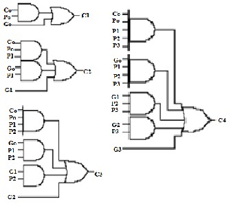
Fig 7 Carry generator
The concept of the carry-select adder is to compute alternative results in parallel and subsequently selecting the correct result with single or multiple stage hierarchical techniques [8]. It enhances the speed performance and increases its area requirements. The Carry Select Adder
The delay of n-bit carry select adder based on an m-bit CLA blocks can be given by the following equation when using constant carry number blocks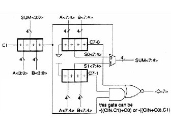
T=tsetup + m tcarry + (n/m) t mux + t sum
Fig 8 8-bit Carry Select Adder
For comparison we have implemented several Modified Booth Encoder multipliers whose partial product are generated by Booth Encoder and then addition is implement by different adder technique . These multipliers were modeled in VHDL and synthesized by using Xilinx ISE Design Suite 13.2
TABLE 2

PERFORMANCE COMPARISON OF 8 BIT MULTIPLIER
divides the number to be added into blocks and forms two sums for each block in parallel (one with a carry in of ZERO
Performance
Parameter
MBM
8 × 8 Multiplier
MBM
MBM
MBM
and the other with a carry in of ONE) [8],[12],[13],[14]. In this adder carry_in is delivered, the correct computation is
(Conventional
Adder)
(RCA)
(CLA)
(CSLA)
chosen using a MUX to get the desired output. Therefore
instead of waiting for carry_in to calculate the sum, the correct output sum is taken as soon as the carry_in get there. The time taken to compute the sum is avoided which results in a good improvement in speed. Fig. 8 shows the implementation of an 8 bits carry-select adder with 4-bit sections. The calculation of two sums is accomplished using
Occupied
Slice
LUT 4- INPUT
Path Delay(Max.) ns
110 98 98 109
212 181 184 210
24.156 26.133 28.326 25.920
two 4-bit ripple-carry adders.
Fan out 2.69 3.73 3.93 3.99
IJSER © 2013
INTERNATIONAL JOURNAL OF SCIENTIFIC & ENGINEERING RESEARCH, VOLUME 4, ISSUE 6, MAY 2013
ISSN 2229-5518
1095
The above table shows the comparison of MBM by use of various adders .In conventional adder occupied more area and less fan out. In comparison use of RCA occupied less area and high fan out but path delay is increase than the conventional adder. As in case of CLA almost occupied the same area as in the case of RCA but path delay is increase and fan out increase .CSLA is best from the above adder cause of path delay is less as comparison to CLA and RCA and high fan in out all of the above. It is much faster adder to add the partial product in multiplication process
In this brief MBM (radix-4) implemented by various adder technique. Partial product generated by booth encoder is added by various adders (conventional adder, RCA, CLA, CSLA). Conventional adder has minimum path delay than the other adder but it occupied large area and less fan out. RCA and CLA are occupied less area and improve fan out. But path delay is increase. CSLA adder is best amongst the above adder .it occupied more area but less than conventional adder and high fan out, less path delay, fastest adder.
[1] S. Shafiulla Basha, Syed. Jahangir Badashah.‛ Design and implementation of Radix-4 based high speed multiplier for ALU’s using minimal partial product‛ International Journal of Advances in Engineering & Technology, July 2012 ISSN: 2231-1963.
[2] Dhanya Geethanjali Sasidharan, Aarathy Iyer ‚Comparison of Multipliers Based on Modified Booth Algorithm‛ International Journal of Engineering Research and Applications (IJERA) ISSN:
2248-9622 www.ijera.com Vol. 3, Issue 1, January -February 2013, pp.1513-1516
[3] S.Jagadeesh, S.Venkata Chary‚Design of Parallel Multiplier– Accumulator Based on Radix-4 Modified Booth Algorithm with SPST‛ International Journal Of Engineering Research And Applications (IJERA) ISSN: 2248-9622 www.ijera.com Vol. 2, issue
5, September-October 2012, pp.425-431
[4] A. R. Cooper, ―Parallel architecture modified Booth multiplier,‖ Proc. Inst. Electr. Eng. G, vol. 135, pp. 125–128, 1988 M. Young, The Technical Writer's Handbook. Mill Valley, CA: University Science, 1989.
[5] Marc Hunger and Daniel Marienfeld, ‚New self-checking booth
multiplier‛, Int. J. Appl. Math, Comput. Sci., Vol.18, No.3, 319–
328,2008
[6] S. Waser and M. J. Flynn, Introduction to Arithmetic for Digital
Systems Designers. New York: Holt, Rinehart and Winston, 1982.
[7] A. R. Omondi, Computer Arithmetic Systems. Englewood Cliffs, NJ:Prentice-Hall, 1994.
[8] Prof. Vojin G. Oklobdzija ‚High-Speed VLSI Arithmetic Units:
Adders and Multipliers‛ September 13, 1999
[9] Weinberger, J.L. Smith, “A Logic for High-Speed Addition”, National
Bureau of Standards, Circulation 591, p. 3-12, 1958.
[10] V.G. Oklobdzija, E.R. Barnes, “Some Optimal Schemes for ALU Implementation in VLSI Technology”, Proceedings of 7th Symposium on Computer Arithmetic, June 4-6, 1985, University of Illinois, Urbana, Illinois.
[11] V. G. Oklobdzija, ‚Simple And Efficient CMOS Circuit For Fast VLSI Adder Realization,‛ Proceedings of the International Symposium on Circuits and Systems, pp. 1-4, 1988.
[12] Earl E. Swartzlander, “Computer Arithmetic” Vol. 1 & 2, IEEE Computer Society Press,1990.
[13] M. Ercegovac, “Digital Systems and Hardware/Firmware Algorithms‛, Chapter 12: Arithmetic Algorithms and Processors, John Wiley & Sons, 1985
[14] O. J. Bedrij, "Carry-Select Adder", IRE Transaction on Electronic
Computers, June 1962
IJSER © 2013