International Journal of Scientific & Engineering Research, Volume 5, Issue 1, January-2014 1853
ISSN 2229-5518
Optimization of Well Placement at Water
Injection and Surfactant Injection in Fractured
Reservoirs by Algorithm Genetic
Reza Ashourizadeh1, Mohammad Amin Gholamzadeh1*
1Department of Petroleum Engineering, Omidiyeh Branch, Islamic Azad University, Omidiyeh, Iran
Email: m.a.gholamzadeh@gmail.com
Abstract— Although waterflooding is an effective process, surfactant flooding is used to recover oil from reservoirs by wettability altera-tion and interfacial tension reduction. Economical effectiveness is a main challenge in feasibility of any EOR method. In this study, we compare oil recovery of both surfactant and water flooding in Reservoirs with various conditions. One of the im-portant optimization variables is well placement. Various methods have been suggested for this problem. Among these, direct optimization, although accurate, is impossible due to the number of simulation required. Optimal placement of up to three injection wells was studied at two fields. One of the Iranian conventional field and a hypothetic fractured field. Injection rate and injection time was also optimized. The net present value of the surfactant flooding projects was used as the objective function.
Index Terms— Waterflooding, Surfactant Flooding, Optimization, Well Placement,Dual Permeability
—————————— ——————————
1 INTRODUCTION
IJSER
NHANCED oil recovery (EOR) is oil recovery by injecting materials that are not present in a petroleum reservoir. One of the important methods in EOR is chemical flood-
ing such as surfactant flooding. Injection of surfactant increas- es the oil recovery [1]. Chemical flooding in the petroleum industry has a larger scale of oil recovery efficiency than water flooding. On the other hand, it is far more technical, costly and risky. Surfactant flooding is used to recover oil from reservoirs by wettability alteration and interfacial tension reduction. Sur- factants have been identified which can lower the IFT between oil and aqueous phase. The reduction of IFT leads to mobiliza- tion of the oil by buoyancy forces. In all the enhanced oil re- covery processes, flow of displacing and displaced fluid in a petroleum reservoir is affected by the wettability of the reser- voir rock [2].
Surfactant flooding process has to be optimized. One of the important optimization variables is well placement. Determin- ing of the location of new wells is a complicated problem which depends on reservoir and fluid properties [3]. Various methods have been suggested for this problem. Among these, direct optimization, although accurate, is impossible due to the number of simulation required.
The optimization algorithm used in this work is the genetic
algorithm. The main characteristic of GA is the ability to work
in a solution space with non-smooth and non-linear topology
where the traditional methods generally fail. A reservoir simu- lator has been used in the present study. Genetic algorithm depends on the principle of artificial intelligence similar to Darwin’s theory of natural selection. The genetic algorithm is coupled with the simulator in order to re-evaluate the opti- mized wells at each iteration [4].
The well location is one of the most important aspects in
production definition. Reservoir performance is highly de-
pendent on well locations [5]. The process of choosing the best location for wells is basically trial and error. It is a time- consuming and demands high computational efforts, since the productivity depends on many variable related to well charac- teristics, reservoir and fluid properties, which can only be un- derstood through numerical simulation. The use of an optimi- zation algorithm to find a good position for the wells can be very useful to the process but it can also lead to an exhaustive search, demanding a great number of simulations to test many possibilities, most of the them disposable [6].
Numerical models are detailed and powerful predictive
tools in reservoir management. While not perfect they are of-
ten the best representation of the subsurface. Optimization
method run these numerical models perhaps thousands of
times reaching for the most profitable solution to reservoir
management questions. Because of the computational time involved optimization methodologies are not used as much as they could be. Various researchers have explored speeding up optimization by either using a speedier evaluation of the ob- jective function or improving the efficiency of the optimization search itself.
2 INTRODUCTION
Enhanced oil recovery (EOR) is oil recovery by injecting materials that are not present in a petroleum reservoir. One of the important methods in EOR is chemical flooding such as surfactant flooding. Injection of surfactant increases the oil recovery [1]. Chemical flooding in the petroleum industry has a larger scale of oil recovery efficiency than water flooding. On the other hand, it is far more technical, costly and risky. Surfactant flooding is used to recover oil from reservoirs by wettability alteration and interfacial tension reduction.
IJSER © 2014 http://www.ijser.org
International Journal of Scientific & Engineering Research, Volume 5, Issue 1, January-2014 1854
ISSN 2229-5518
Surfactants have been identified which can lower the IFT between oil and aqueous phase. The reduction of IFT leads to mobilization of the oil by buoyancy forces. In all the enhanced oil recovery processes, flow of displacing and displaced fluid in a petroleum reservoir is affected by the wettability of the reservoir rock [2].
Surfactant flooding process has to be optimized. One of the
important optimization variables is well placement.
Determining of the location of new wells is a complicated problem which depends on reservoir and fluid properties [3]. Various methods have been suggested for this problem. Among these, direct optimization, although accurate, is impossible due to the number of simulation required.
The optimization algorithm used in this work is the genetic
algorithm. The main characteristic of GA is the ability to work in a solution space with non-smooth and non-linear topology where the traditional methods generally fail. A reservoir simulator has been used in the present study. Genetic algorithm depends on the principle of artificial intelligence similar to Darwin’s theory of natural selection. The genetic algorithm is coupled with the simulator in order to re-evaluate the optimized wells at each iteration [4].
The well location is one of the most important aspects in production definition. Reservoir performance is highly
dependent on well locations [5]. The process of choosing the
It was applied in primary recovery stage developed with ver- tical wells. The work utilizes parallel computing with inten- tion to accelerate the process. Mezzeomo and Schiozer [9] proposed an optimization procedure based on reservoir simu- lation that evaluates both individual and wells and field per- formance. The methodology helps managers to make deci- sions that lead to an adequate recovery for the reservoirs, max- imizing profits and minimizing risks associated to the invest- ments.
The process to choose the location and the number of wells
is not a simple procedure because of number of variables in-
volved. The well behavior depends on the reservoir properties
and interaction with other wells and it can only be predicted
through numerical simulation. Therefore, each combination of
number and well position must be tested by engineers. Many studies propose the use of an optimization algorithm to re- duce the engineer’s effort. The genetic algorithm has been used world-wide for this purpose due to its ability to work in a solution space with non-smooth and non-linear topology, where the traditional methods generally fail. The GA is an optimization method based on natural evolution process. It operates by defining an initial population with N individuals. Each individual is evaluated according to the value of the fit- ness function. Three main types of rules are used to drive the
process: selection (or reproduction), crossover and mutation.
IJSER
best location for wells is basically trial and error. It is a time-
consuming and demands high computational efforts, since the
productivity depends on many variable related to well
characteristics, reservoir and fluid properties, which can only
be understood through numerical simulation. The use of an
optimization algorithm to find a good position for the wells can be very useful to the process but it can also lead to an exhaustive search, demanding a great number of simulations to test many possibilities, most of the them disposable [6].
Numerical models are detailed and powerful predictive
tools in reservoir management. While not perfect they are often the best representation of the subsurface. Optimization method run these numerical models perhaps thousands of times reaching for the most profitable solution to reservoir management questions. Because of the computational time involved optimization methodologies are not used as much as they could be. Various researchers have explored speeding up optimization by either using a speedier evaluation of the objective function or improving the efficiency of the optimization search itself.
3 BACKGROUND
Optimum reservoir management is an important theme in petroleum industry. Most of the studies related to reservoir performance optimization focus the well placement.
Aanonsen et al [7] proposed a method to optimize well lo- cations under geological uncertainties based on response sur- faces and experimental design. Multiple regression and kriging were used to reduce the number of simulation runs. A methodology to optimize the number and location of producer well in new fields was developed by Pedroso and Schiozer [8].
Selection consists of determining a set of elite individuals from
the population, based on fitness to the objective function: in-
dividuals with best objective function are candidates for elite.
Crossover is the operation that tries to retain good features
from the previous generation. It enables the algorithm to ex-
tract the best genes from different individuals and recombine them into potentially superior children. Mutation is the opera- tion responsible to add diversity in a new generation.
Bittencourt and Horne [10] developed a hybrid algorithm based on direct methods such as genetic algorithm, polytope
search and tabu search to obtain the optimal solution for prob- lems related to reservoir development. Simulator was used as a data generator for the evaluation of the objective function, which involved an analysis of cash flow. Guyaguler et al [11,
12] have also been used genetic algorithm to reduce computa-
tional burden in well placement optimization problem upon uncertainties. Application of genetic algorithm and simulated annealing are presented by yang et al [13] to optimize produc- tion-injection operation systems. Ozdogan et al [14] also ap- plied hybrid genetic algorithm for optimization of well place- ment under time-dependent uncertainty.
4 SURFACTANT-FLOODING
Surfactants are polar compounds, consisting of an Am- phiphilic molecule with both hydrophilic and hydrophobic parts. The surfactants are classified as: anionic, cationic, Am- photeric and nonionic depending upon the nature of the charge present on hydrophilic group. The two basic features of the surfactants that make them unique for use in oil industry are their ability to lower oil-water interfacial tension and alter the reservoir wettability. Surfactant functions work by adding
IJSER © 2014 http://www.ijser.org
International Journal of Scientific & Engineering Research, Volume 5, Issue 1, January-2014 1855
ISSN 2229-5518
certain concentrations of surfactants to injection water to re- duce the interfacial tension (IFT) between displacing and dis- placed phases [15]. In the process of surfactant flooding, the surfactant adsorbs onto the oil-water interface and surface of rock which may also make a wettability change of rock [16]. The experiment shows that the oil drops are becoming easier to deform when the water-oil interfacial tension reduces, so the resistance force lowers when the oil drops flow through the pore throat. With the decrease of IFT, the crude oil can disperse in the surfactant solution, meantime, the surface of oil drops are charged after adsorption, so the oil drops are not easy to stick onto the surface of rock particles.
The objective of this study is the simulation and optimiza-
tion of surfactant flooding at two different reservoirs; conven-
tional and fractured reservoirs. The schematic of the conven- tional and fractured reservoir is presented in Fig.1 and Fig.2 respectively.
IJSEFig. 4.RThe Schematic of Fractured Oil Reservoir
Fig. 1. The Schematic of the Conventional Oil Rreservoir
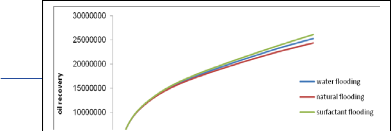
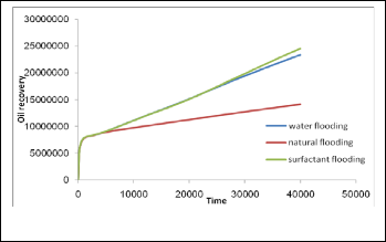
Then the surfactant flooding and waterflooding processes
were simulated at both reservoirs at three injection rates. Fi-
nally the cumulative oil production respect to the natural pro-
duction for both reservoirs was compared. The comparison
between the plots of both reservoirs is shown at Fig. 5 to Fig.
19. The Oil recovery (%) for conventional reservoir and three
injection rates and three cases (waterflooding and surfactant flooding and natural flooding) has shown at Table 1 and table
2.
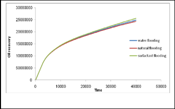
Fig. 2. The Schematic of the Fractured Oil Reservoir
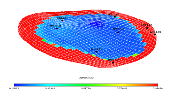
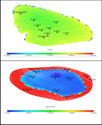
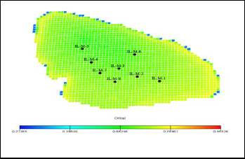
As shown in the figures 1&2, each reservoir consists of eight production wells. The Iranian conventional oil reservoir is located at ILAM formation. The name of the wells is based on the formation name. The fractured reservoir is a hypothetic one. In the first step, two new injection wells were located at each reservoir. The location of injection wells is shown at Fig.
3 and Fig. 4 respectively. The color bar shows the oil satura-
tion at the reservoir.
Fig. 5. Conventional Reservoir at Injection# 1 at 500 STB/day
IJSER ©
http://www.i
International Journal of Scientific & Engineering Research, Volume 5, Issue 1, January-2014 1856
ISSN 2229-5518
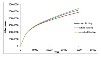
TABLE 1
OIL RECOVERY AT CONVENTIONAL RESERVOIR AT INJECTION# 1
State | Oil Recovery (%) |
Natural Flooding | 11.21 |
Waterflooding at 500 STB/day | 11.251 |
Surfactant Flooding at 500 STB/day | 11.825 |
Waterflooding at 1000 STB/day | 11.657 |
Surfactant Flooding at 1000 STB/day | 12.043 |
Waterflooding at 2000 STB/day | 11.977 |
Surfactant Flooding at 2000 STB/day | 12.48 |
Fig. 7. Conventional Reservoir at Injection# 1 at 2000 STB/day
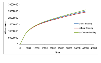
TABLE 2
OIL RECOVERY AT CONVENTIONAL RESERVOIR AT INJECTION# 2
State | Oil Recovery (%) |
Natural flooding | 11.21 |
Waterflooding at 500 STB/day | 11.562 |
Surfactant flooding at 500 STB/day | 11.969 |
Waterflooding at 1000 STB/day | 11.869 |
Surfactant flooding at 1000 STB/day | 12.313 |
Waterflooding at 2000 STB/day | 12.354 |
Surfactant flooding at 2000 STB/day | 12.817 |
Fig. 8. Conventional Reservoir at Injection# 2 at 500 STB/day
Fig. 9. Conventional Reservoir at Injection# 2 at 1000 STB/day
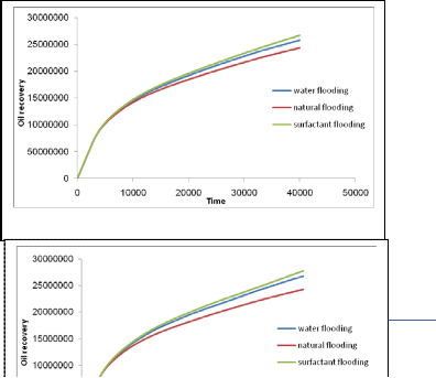
First, we placed the injection# 1 well and did all simula- tions. As it can be seen, by increasing the injection rate, the waterflooding and surfactant flooding oil recoveries has in- creased respect to natural flooding state. Second, without presence of the injection# 1, we placed the injection# 2 well and repeated all steps. The results of this case are similar to the previous case. As it can be seen, the surfactant flooding oil recovery is greater than the waterflooding oil recovery with the same injection rate. The surfactant flooding oil recovery for injection# 2 is greater than the injection# 1 case. So we can conclude that the surfactant flooding is strongly dependent to the well location and injection rate. Another point is that these results are for a limited time of simulation. And ultimate oil recovery for waterflooding is about 30 to 40 % greater than the natural state and surfactant flooding ultimate recovery is ap- proximately 10 to 15 % greater than waterflooding state. By doing this, we just wanted to show that surfactant flooding is an efficient method.
Both un-fractured and fractured formations will be ad- dressed in this study. The driving force for displacement of oil
R © 2014 ww.ijser.org
International Journal of Scientific & Engineering Research, Volume 5, Issue 1, January-2014 1857
ISSN 2229-5518
in un-fractured systems is primitively the pressure gradient developed by displacing fluids from the injection well to the production well. This pressure gradient may be only a small contributor in fractured formations. In this case, spontaneous imbibition includes capillary pressure gradients and buoyan- cy, or gravity drainage. The contribution due to capillary pres- sure gradient may be diminished because of low interfacial tension.
In a fractured reservoir, fluids exist in two interconnected systems:
1- The rock matrix, which usually provides the bulk of the reservoir volume
2- The highly permeable rock fractures
Wettability and matrix block size are two major factors in
fluid transfer between fracture and matrix. For an oil-wet frac- tured reservoir, containing only oil and water, water from an injection well or from an aquifer can flow in fractures easily and much faster than in the matrix. Gravity drainage can pro- duce oil if the matrix block is thick enough to overcome the negative water-oil capillary pressure. This is true particularly for oil-wet fractured reservoirs [17].
If the matrix blocks are linked only through the fracture sys-
tem, this conventionally could be regarded as a dual porosity single permeability, since fluid flow through the reservoir take
place only in the fracture network with the matrix block acting
Fig. 13. Dual Permeability Reservoir at Injection# 1 at 2000 STB/day
as sources. If there is the possibility of flow directly between neighboring matrix blocks, there is conventionally considered to be a dual porosity dual permeability systems. So we did simulations for dual porosity and dual permeability cases. Results of dual permeability cases are shown at Fig 11 to Fig
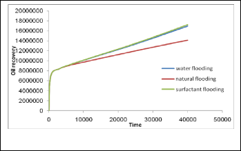
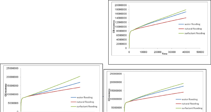
16. The oil Recoveries (%) has shown at Table 3 and Table 4.
Fig. 14. Dual Permeability Reservoir at Iinjection# 2 at 500 STB/day
Fig. 11. Dual Permeability Reservoir at Injection# 1 at 500 STB/day
Fig. 15. Dual Permeability Reservoir at Injection# 2 at 1000 STB/day
w
International Journal of Scientific & Engineering Research, Volume 5, Issue 1, January-2014 1858
ISSN 2229-5518
ing matrix blocks.
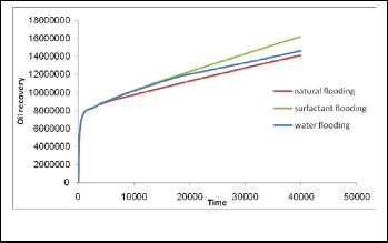
Finally we did simulation for dual porosity reservoirs. Results
of dual porosity case are shown in Fig. 17 to Fig. 19. The oil
Recoveries (%) has shown at Table 5.
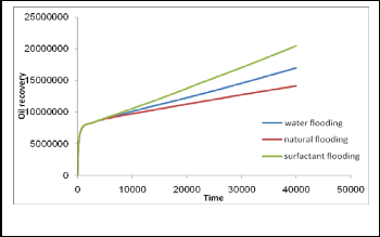
TABLE 3
OIL RECOVERY AT DUAL PERMEABILITY RESERVOIR AT INJECTION# 1
Fig. 12. Dual Permeability Reservoir at Injection# 1 at 1000 STB/day
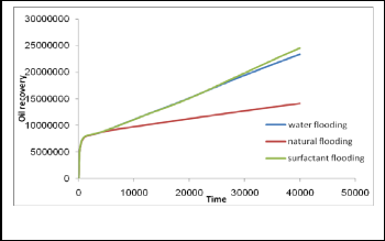
TABLE 4
OIL RECOVERY AT DUAL PERMEABILITY RESERVOIR AT INJECTION# 2
Fig. 13. Dual Permeability Reservoir at Injection# 1 at 2000 STB/day
At First, we placed the injection# 1 well and did all simula- tions. As it can be seen, by increasing the injection rate, the waterflooding and surfactant flooding oil recoveries has in- creased respect to natural flooding state. Secondly, without presence the injection# 1, we placed the injection# 2 well and repeated all steps. The results of this case are similar to the previous case. As it can be seen, the surfactant flooding oil recovery is greater than the waterflooding oil recovery with the same injection rate. The surfactant flooding oil recovery for injection# 1 case is different from the recovery of injection# 2. So we can conclude that the surfactant flooding is strongly dependent to the well location and injection rate. Another point is that these results are for a limited time of simulation, so ultimate oil recovery for waterflooding and surfactant flooding are greater than such values. By doing this, we just wanted to show that surfactant flooding is an efficient method and dual- permeability reservoirs behave similar to conven- tional reservoirs. One reason is that in such reservoirs, fluid flow through the reservoir not only in the fracture network and there is the possibility of flow directly between neighbor-
TABLE 2
OIL RECOVERY AT DUAL PERMEABILITY RESERVOIR AT INJECTION# 2
State | Oil Recovery (%) |
Natural flooding | 14.055 |
Waterflooding at 500 STB/day | 14.93 |
Surfactant flooding at 500 STB/day | 14.93 |
Waterflooding at 1000 STB/day | 16.14 |
Surfactant flooding at 1000 STB/day | 16.14 |
Waterflooding at 2000 STB/day | 16.88 |
Surfactant flooding at 2000 STB/day | 16.88 |
As it can be seen, the surfactant flooding process is not an efficient process respect to waterflooding process in dual- porosity reservoirs since the oil recovery of surfactant flooding is the same as the water flooding oil recovery. One reason is that the matrix blocks are linked only through the fracture system and fluid flow through the reservoir takes place only in the fracture network with the matrix block acting as sources and matrix networks are not interconnected and surfactant is not in direct contact to matrix network. In dual-porosity reser- voirs, if we place an injection well near the production wells (like injection# 2), the water and surfactant flow through the
IJSER © 2014 http://www.ijser.org
International Journal of Scientific & Engineering Research, Volume 5, Issue 1, January-2014 1859
ISSN 2229-5518
fractures and early breakthrough occurs and water flooding and surfactant flooding recoveries maybe smaller than natural flooding. Surfactant has to be in direct contact to matrix to mobilize the oil by wettability alteration and IFT reduction mechanism. So we conclude that the surfactant flooding is inefficient process in dual porosity reservoirs and the behavior of these reservoirs is unlike to the dual permeability reser- voirs.
4 CONCLUSION
In Conventional reservoir the surfactant flooding is strong- ly dependent to the well location and injection rate. Another point is that these results are for a limited time of simulation. According to tables 1 and 2, ultimate oil recovery for water- flooding is about 30 to 40 % greater than the natural state and surfactant flooding ultimate recovery is approximately 10 to
15 % greater than waterflooding state. By doing this, we just
wanted to show that surfactant flooding is an efficient meth- od.
Tables 3 and 4 show that the surfactant flooding is strongly dependent to the well location and injection rate in dual per- meability reservoir. Another point is that these results are for a
limited time of simulation, so ultimate oil recovery for water-
REFERENCES
[1] Zhangxin Chen. Yuanle Ma. Guo Chen.:'' A sequential numerical chemical compositional simulator'', Transport porous media,2006
[2] Benyamin Yadali Jamaloei. R Kharrat: '' Analysis of microscopic displacement Mechanisms of Dilute surfactant flooding in oil-wet and water-wet porous media'', Transport porous media,2008
[3] Baris Guyaguler: '' Optimization of well placement in a Gulf of Mexico Waterflooding Project'', SPE, Ronald N. Horne , SPE, (Stanford university) leah Rogers, 2000
[4] Wathiq J. AL-Mudhafar .: '' Using optimization Techniques for determining optimal locationsof additional oil wells in south Rumaila oil field'', SPE, Iraqi south oil company; Mohammed S. AL-jawad, SPE, Baghdad university, 2010
[5] O.Badru.:'' Well Placement Optimization in Field Development'', SPE, Stanford
U. and C. S. Kabir, SPE, Chevron Texaco overseas petroleum
[6] Celio Maschio.:'' Production Strategy Optimization Using Genetic Algorithm and Quality Map'', SPE, Lincoln Nakajima, SPE, and Denis J. Schiozer, SPE, Unicamp, 2008
[7] Anonson, S.I., Eide, A. L., Holden, L.: ‘’ optimization reservoir performance under with Application to well location’’, SPE 30710, SPE Annual Technical conference and Exhibition, Dallas, U.S.A., Oct, 22-25, 1995
[8] Pedroso Jr., C., Schiozer ,D. J.: ‘’ optimization location of well in fluid development using reservoir simulation and parallel computing’’, Rio oil& Gas, Rio de Janeiro, Brazil, 2000
[9] Mezzomo, C.C., Schiozer, D.J.: ‘’Methodology for water injection strategies planning optimization using reservoir simulation’’, Paper 2002-121, 2002
Petroleum society’s Canadian international Petroleum conference, Calgary,
IJSER
flooding and surfactant flooding are greater than such values.
By doing this, we just wanted to show that surfactant flooding
is an efficient method and dual- permeability reservoirs be-
have similar to conventional reservoirs. One reason is that in
such reservoirs, fluid flow through the reservoir not only in
the fracture network and there is the possibility of flow direct- ly between neighboring matrix blocks.
Surfactant injection method in an oil-wet, dual-porosity model may not be effective because of the following reasons:
1-Pressure gradient may be too small to displace oil from the
matrix in fractured formations in contrast to the homogenous un-fractured reservoirs.
2-High permeable fractures could act like thief zones and by- pass small fractures. In this case using mobility control agents like foam might be considered
3-Gravity difference between fracture and matrix could be ineffective to mobilize oil by chemical flooding depending on the matrix block height. The smaller block height, the less the effectiveness of gravity drainage.
Alberta, Canada, Jun. 11-13, 2002
[10] Bittencourt, A.C., Horne, R.N.: ‘’reservoir Development and design optimization’’, SPE 388895, SPE Annual Technical conference and Exhibition, San Antonia, TX, Usa., Oct. 5-8, 1995
[11] Guyaguler, B., Horne, R.N.:’’ uncertainty Assessment of well placement optimization’’, SPE 71625, SPE Annual Technical conference and Exhibition, New Orleans, Louisiana, USA., 30 Sep. to 3 Oct, 2001
[12] Guyaguler, B., et al: ‘’ optimization of well placement in Gulf of Mexico waterflooding project’’, SPE 63221, SPE Annual Technical conference and Exhibition, Dallas, Texas, USA., Oct. 1-4, 2000.
[13] Yang, D, Zhang, Q. and Youngan GU, Y.’’ Integrated optimization and control of the production- injection operation systems for Hydrocarbon reservoirs’’, Journal of petroleum science and Engineering 37, 69-81, 2003.
[14] Ozdogan, U. and Horne, R. N. ‘’ optimization of well placement under time- dependent uncertainty’’, SPE reservoirs Evaluation& Engineering, Vol. 9.N.2, April, 2006, PP. 135-145
[15] V. Hornof, A, Chaaroui, ‘’ Viscosity of surfactant- polymer solution’’, SPE
11775, this Paper was presented at the international symposium on oilfield and Geothermal chemistry held in Denver Co, June 1-3, 1983.
[16] W. Kang, et al.: ‘’ Mechanism of Tertiary oil recovery ,’’ Chemistry industry press, 1996.
[17] M.kiani, Kazemi: '' Pilot testing issues of chemical EOR in large fractured
carbonate reservoirs'', SPE, Colorado school of mines,2011
IJSER © 2014 http://www.ijser.org