International Journal of Scientific & Engineering Research, Volume 3, Issue 11, November-2012 1
ISSN 2229-5518
Optical Supervisory Channel Implementation
Chittajit Sarkar
—————————— ——————————
he Optical Supervisory Channel (OSC) is an additional
Twavelength usually outside the EDFA amplification band
1 2 3 n
1
at
2 3 n
(at 1510 nm, 1620 nm, 1310 nm or another proprietary
wavelength). The OSC carries information about the mul- ti-wavelength optical signal as well as remote conditions at the optical terminal or EDFA site. It is also normally used for re- mote software upgrades and user (i.e., network operator) Network Management information. ITU standards suggest that the OSC should utilize an OC-3 signal structure (though
at 1510nm
input
1510/1550
Coupler
EDA OPTI- CAL MOD- ULE
1510nm
1510/1550
Coupler
output
some vendors have opted to use 100 megabit Ethernet or an- other signal format). Unlike the 1550 nm band client signal- carrying wavelengths, the OSC is always terminated at inter- mediate amplifier sites, where it receives local information
at
1510 nm
OSC
CONTROL
BOARD OSC
at
1510 nm
before retransmission. The optical supervisory channel is used for maintenance purposes and is accessed at each ILA. The optical supervisory channel provides transport of Order Wire, two E1 and one Ethernet Data (user proprietary) NMS data.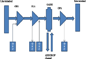
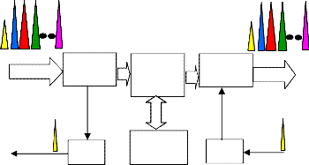
Fig.1: Block diagram of DWDM system
Fig.2: amplifier with OSC in DWDM system
All OSC related functions including transmission, termination and processing shall be integrated within a single card.The OSC channel shall be provided at 1510nm wavelength and shall have capacity of at least 2Mbps.The OSC transmitter and receiver behaviour at the Inline Amplifier/Booster/Pre-Amp shall be monitored through EMS via suitable alarms.
Another function of the OSC is the recovery of the transmis- sion from a failed line.In case of a fibre cut on a section of the line, or subsequent Automatic Shutdown of the related ampli- fiers, the OSC is used to advice recovery of the line.The OSC shall continue to operate even after the automatic Shutdown of the related amplifiers and when correctly received at the corresponding OSC unit of the recovered section, the amplifi- ers are restarted.
————————————————
Chittajit Sarkar is currently working as Assistant Professor in Swami Vi- vekananda Institute of Science and Technology and pursuing PhD from department of RadioPhysics and Electronics, Calcutta University.E-mail: chittajit_sarkar@yahoo.co.in
MUX155 chip supports 4 E1 line and one Ethernet interface [1]. E1 line will be used for EOW and NMS. TS1, TS2, and TS3 will be assigned for EOW data and rest time slots are assigned
IJSER © 2012
International Journal of Scientific & Engineering Research, Volume 3, Issue 11, November-2012 2
ISSN 2229-5518
for NMS data. The time slot selection and processing of data
will be done by CPU[3].The Framing of E1 will be done by framer section of mapper chip.This is software configurable. According to requirement this framing can be used or by- passed. Only first E1 can be framed or bypassed through ST_BUS interface. Extra
One Ethernet Interface and two G.703 interfaces will be provi- ded for the client. Other E1 will be used in future. The maper chip will map all these E1 lines and Ethernet to 1510 complied electrical signal.This electrical signal will be transmitted to the
1510 optical SFP module [2] by using recovered TX clock from CDR.The 1510 optical SFP module converts the electrical sig- nal to optical signal (1510nm).This optical signal (1510nm) will be transmitted to the optical amplifier or OADM or ROADM. This optical signal (1510nm) coming from ampli- firs/OADM/ROADM enters into 1510 optical SFP module. The
1510 optical SFP module converts the optical signal to electri- cal signal. This received electrical signal enters into the CDR.The CDR extracts data and
Clock from the received signal. This received clock will be used by the transmitter section as transmitter clock. Then the MUX155 mapper chip [2] demaps the received data into 4 E1 and One Ethenet.The Framer Section will deframe the 1st E1 data if it is framed one.Then the CPU will extract assigned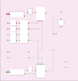
time slots for EOW and NMS data.The EOW data or voice will be processed by EOW module for communication.
OSC Data Path Block Diagram
The diagnostic functions, alarm and warning features are pro-
vided via an I2C serial interface. The transceiver uses a
1511nm DFB laser and an APD receiver to provide an optical link power budget of 44dB. The transceiver connects to a standard 20-pad connector for hot plug capability. This allows the system designer to make configuration changes or mainte- nance by simply plugging in different types of transceivers without removing the power supply from the host system.
The transceiver has a blue bail-type latch, which offers an easy
and convenient way to release the module. The latch is com- pliant with the SFP MSA.The transmitter and receiver DATA interfaces are AC coupled internally. LV-TTL Transmitter Dis- able control input and Loss of Signal output interfaces are also provided.The transceiver operates from a single +3.3V power supply over an operating case temperature range of -5°C to
+70°C. The housing is made of metal for EMI immunity. Communication between OSC & WDM modules in ILA is shown in fig.1. The 1510 optical channel is terminated at each optical node and the new channel is generated from that node to next node.The supervisory channel is generated and re- ceived from both east and west direction. For ILA there are two OSC channel (only one card).Before entering to the ampli- fier, the 1510nm will be decoupled from the main channel and received by the OSC module. The OSC module converts this optical signal to electrical signal (by 1510 SFP). This electrical signal is processed by the processor.The processor will segre- gate the EOW and NMS data. The processor will have the in- formation of where to send the data. Next the OSC channel
To/From Amplifier
Module
1510 nm
Optical
155M
Framed E1 I/F
couples the 1510nm signal with the amplified C-band signal
and moves to OADM/ROADM.
External E1 I/F External E1 I/F External E1 I/F
External E1 I/F
RJ-48
Jack
RJ-48
Jack
RJ-48 Jack
RJ-48 Jack
Unframed E1 I/F Unframed E1 I/F
Diff. Line Driver/ Receiver
This is optical interface for Optocal Supervisory channel.
External
Ethernet I/F
External
Ethernet I/F
To/From Amplifier
Module
1510 nm
Optical
Framed E1 I/F
E to W W to E
MUX155 chip supports 4 E1 line and one Ethernet interface. Out of 4 E1 one E1 for data (EOW and NMS) transmission will be used. The Framing of E1 will be done by framer section of mapper chip.This is software configurable. The maper chip will map all these E1 lines and Ethernet to 1510 complined electrical signal. The 1510 optical SFP module convertes the electrical signal to optical signal. This optical signal (1510nm) will be transmitted to the optical amplifier or OADM or
Fig.3: Dataflow through OSC channel
The 1510 SFP fiber optic transceiver[2] with integrated digital diagnostics monitoring functionality provides a quick and reliable interface for optical supervisory channel applications.
ROADM.
Microprocessor acts as time slot assigner of E1 line.It extracts
IJSER © 2012
International Journal of Scientific & Engineering Research, Volume 3, Issue 11, November-2012 3
ISSN 2229-5518
EOW data and NMS data from 1510 OSC data for receiving side.It inserts EOW and NMS data to 1510 OSC data for transmitting side.Through its I2C bus temperature of the OSC card can be monitored. MPC8321 supports four TDM interfac- es.out of four TDM, two are used and two are left for future implementation.
FPGA is used to provide the ST_BUS interface to mapper chip.
Some optional E1 interfacing is provided through quad line driver.
MUX155 chip supports one Ethernet interface .Two MUX155 provide two user Ethernet interface for EAST and WEST OSC communication.
The processor chip supports 4 E1 interface. Only 2 E1 lines will be used for both EAST and WEST communication. For 4 degree communication, 4 E1 lines will be used that means all four TDM interfaces of the processor will be used. This is four sided communication.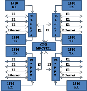
Fig.4: four degree OSC communication
minal equipment and ILAs for alarm surveillance, overhead information transmission and remote amplifier control. The OSC data is transmitted along the fiber used for the main sig- nal.The OSC data rate is 155Mbps but in this implementation only one E1 line -2 Mbps is used for OSC. Processor MPC8321supports upto four degree ROADM configura- tion.For four degree configuration four mapper chip and four
1510 SFP fiber optic transceivers are required.
[1] Data sheets of “Ethernet and Quad E1 to Dual 155M Mul- tiplexer FPGA” part no. GC96155A-BG by GEMSTONE. http://www.gemstone.com.tw/product/GC96155A- BG.asp.
[2] OC-3 1510nm Optical Supervisory Channel SFP Transceiver, part No. TRCE03KE2C000C3 by OPLINK Communications Inc.
[3] MPC8323E PowerQUICC II Pro Integrated Communica- tions Processor Family Hardware Specifications,Rev.4: http://www.freescale.com/webapp/sps/site/prod_sum mary.jsp?code=MPC8321&fr=g.
The OSC is an Optical interface placed between Optical Ter-
IJSER © 2012