International Journal of Scientific & Engineering Research, Volume 6, Issue 3, March-2015 550
ISSN 2229-5518
Multi-channel Image Deblurring using
Blind Deconvolution
Gururaju 1, Siddaraju K. 2
1. Research Scholar
2. Research Scholar and Assistant. Professor of Computer Science, .Maharani’s Science College for
Women, Mysore-570005, Karnataka, India
Abstract_The proposed restoration involves a DCT domain zonal filtering pre-processing followed by a post- processing step of time domain deconvolution. The technique applies to situations on which the scene consists of a finite support object against a uniformly black, gray or white and color backgrounds. Preliminary simulations in noise- free and noisy cases are conducted. The results are compared with standard Median filter for image denoising and the proposed blind restoration scheme is shown to exhibit improvement in SNR.
—————————— ——————————
The process of simultaneously estimating the PSF and restoring an unknown image using partial or no information about the imaging system is known as Blind Image restoration. For the linear degradation model when the noise item is neglected, it is specially referred to as blind deconvolution. There exit several motivating factors for the use of blind deconvolution in image processing applications. In many situations, it is difficult to accurately measure the degradation using calibration or on-line identification techniques; in addition, it is costly, dangerous, or physically impossible to obtain a priori information about the scene to be imaged. For example, in remote sensing and space imaging, fluctuations in the PSF are difficult to characterize as a random process, and there is difficulty in statistically modeling the original image. In addition, the use of adaptive optics system is often too expensive for some observation facilities, and the potential for phase error exists with cheaper partially compensating systems. Thus, technique such as blind deconvolution will be required.
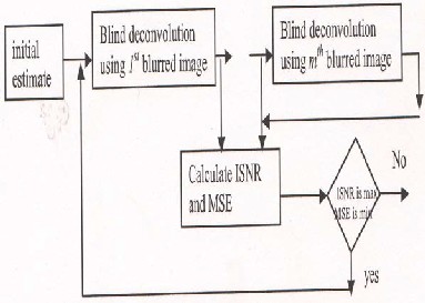
Fig: 1 Iterative Multi-channel blind image restoration
Computer simulation results are shown in the section 2.2 for multi-channel blind restoration using blind deconvolution. Classical Lena and Barbara colored images shown in fig 3 were chosen as test images. Three blurred channels of the same
original image are considered. The images are
IJSER © 2015 http://www.ijser.org
International Journal of Scientific & Engineering Research, Volume 6, Issue 3, March-2015 551
ISSN 2229-5518
blurred wsith motion blur at an angle of 20,30,40 degrees. The blurred images are passed through a deblurring filter iterative blind deconvolution. In case of blind deconvolution the blur function or the Point Spread Function (PSF) is unknown or very little statistical information is available about the original image. An initial guess on the PSF is made the guessed PAF is convolved with the degraded image in order to obtain an estimate of the true image. The Improvement in Signal to Noise Ratio (ISNR) and Mean Square Error (MSE) is found. The experiment is repeated until we get a appropriate guess of PSF for which the ISNR is maximum and MSE is minimum. This final PSF is then deconvolved with the degraded image in order to obtain the estimate of true image. These steps are repeated for all the channels in order to obtain the restored images; from the multiple restored images a single output image is obtained which satisfies most of the assumption made about the true image.
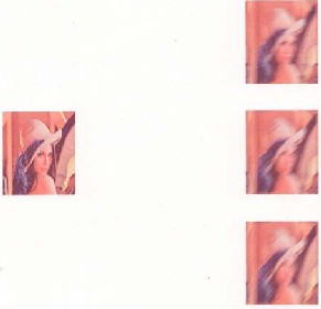
Fig.2 a: Original Lena image with SNR- 25 dB for
1st Channel, SNR -20 dB for 2nd Channel and
SNR=15dB for 3rd channel

Fig.2b: Restored Lena with ISNRI=5.6260dB for 1st channel, ISNR2=5.2743dB for 2nd channel, ISNR3=5.0615dB for 3rd channel and MSE=189
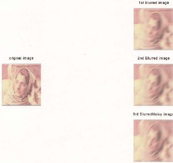
Fig 3a: Original Barbara image with SNR -25dB for
1st channel, SNR-20 dB for 2nd channel, SNR=15dB
for 3rd channel
IJSER © 2015 http://www.ijser.org
International Journal of Scientific & Engineering Research, Volume 6, Issue 3, March-2015 552
ISSN 2229-5518

Fig3b: Restored Barbara with ISNR1=2.3492dB for
1st channel, ISNR2=2.6013 dB for 2nd channel, ISNR=2.7203dB for 3rd channel and MSE=393.91
The presence of noise is visually annoying and makes it more difficult to perform tasks such as image restoration, segmentation, recognition, and scene interpretation. It then becomes desirable to construct a good estimate of the original image from the blurred noisy observations. Initially Median filters were considered to remove the noise present in the image. Median filters effectively remove the noise by substituting the pixel position with the median of the input data. Intuitively the filtering should be applied only to the corrupted pixels while leaving those uncorrupted ones intact.
We have proposed a new noise removal technique called zonal coding or zonal filter for multichannel color images. A zonal mask is applied to the low frequency components and higher frequency components are discarded. Thus the noise, which is present in the image, is filtered or removed. Experimental results show that Zonal filters have proven to achieve a good performance
over Median filters.
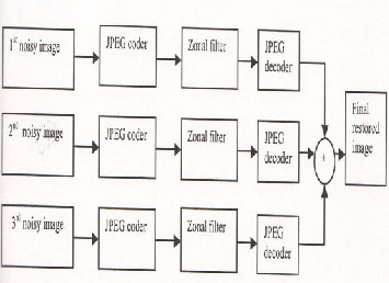
Fig4: Multi-Channel restoration using zonal filter
Computer simulation results for multichannel colored image denoising using zonal filter are shown in section 3.2. The classical Lena and Barbara colored imaged shown in fig 4.3 were chosen as test images. Initially the experiments were carried with median filters and the results were compared with zonal filters.
Three different noisy versions of the test image were considered which were corrupted by AWGN (SNR-25dB,SNR-20dB and SNR-15dB). Then the degraded or the noisy images were compressed into a JPEG format. Zonal mask shown in the fig
4.2a was applied i.e., 8x8 block DCT was considered and the mask was applied only to the lower frequency components ant the higher frequency components were discarded as most of the noise resides in the higher frequency components. Thus the noise, which is present in the image, is removed to greater extent. This process is applied to all the blocks of the entire image. The resultant images were subjected to inverse DCT and the images obtained were the estimate of the true image. Finally from the multiple-channels a single output image is obtained which satisfies most of the assumption made about the true image.
IJSER © 2015 http://www.ijser.org
International Journal of Scientific & Engineering Research, Volume 6, Issue 3, March-2015 553
ISSN 2229-5518
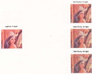
Fig5a: original Lena using Median filter with SNR-
25dB for 1st channel, SNR-20dB for 2nd channel and
SNR-15dB for 3rd channel
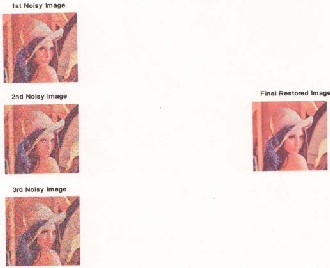
Fig5b: Restored Lena with ISNR1=2,456dB for 1st channel, ISNR2=3.5840dB for 2nd channel, ISNR3=4.0231dB for 3rd channel and MSE=280
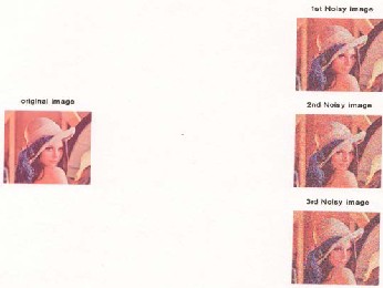
Fig 6a: Original Lena using zonal filter with SNR-
25dB for 1st channel, SNR-20dB for 2nd channel and
SNR-15dB for 3rd channel at 0.25 Bit Rate
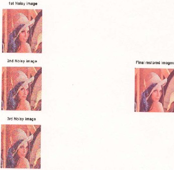
Fig6b: Restored Lena with ISNR1=4.9935dB for 1st channel, ISNR2=5.5840dB for 2nd channel, ISNR3=6.0231dB for 3rd channel and MSE=199
IJSER © 2015 http://www.ijser.org
International Journal of Scientific & Engineering Research, Volume 6, Issue 3, March-2015 554
ISSN 2229-5518

Fig 7a: Original Barbara using Median filter with SNR-25dB for 1st channel, SNR-20dB for 2nd channel and SNR-15dB for 3rd channel
I. Single-Input Multi-Output:- Barbara Image
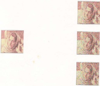
Fig 8a: original Barbara using zonal filter with SNR-25dB for 1st channel, SNR-20dB for 2nd channel and SNR-15dB for 3rd channel for 0.25 Bit Rate
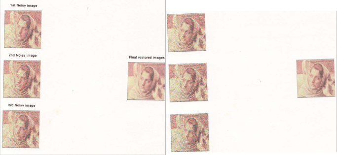
Fig7b: Restored Barbara with ISNR1=26.41dB for
1st Channel, ISNR2=3.5840dB for 2nd channel, ISNR3=3.9912dB for 3rd channel and MSE=480
Fig. 8b: Restored Barbara with ISNR1=3.5497dB for
1st channel, ISNR2=4.4923 for 2nd channel, ISNR3=5.9945 for 3rd channel and MSE=420.54
IJSER © 2015 http://www.ijser.org
International Journal of Scientific & Engineering Research, Volume 6, Issue 3, March-2015 555
ISSN 2229-5518
The proposed Multi-Input Single-Output model of section 4.6 is used for restoring blurred noisy images. Computer simulation results for multichannel restoration of blurred noisy colored image using zonal filter is shown in section 4.1. The classical Lena and Barbara colored images shown in fig 4.3 were chosen as test images. Initially the experiments were carried with median filters and the results were compared with zonal filters.
Three different Blurred Noisy versions of the test image were considered which were corrupted by AWGN and motion blur (BSNR1-
60dB for 1st channel, BSNR2-40dB for 2nd channel and BSNR3-50dB for 3rd channel), which is represented by.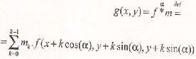
Where ‘g’ denote the observed image, degraded by a motion blur with a done dimensional kernel m=(m1,…., mK) at an angle a, ‘f’ the original image degraded according to Eq(5.1). The motion blur in each channel is assumed at an angle of 20,30 and
40 degrees. The blurred nosy images were
compressed into a JPEG format. Zonal mask was applied to the blurred nosy versions in order to remove the noise contained in it i.e., 8x8 block DCT was considered and the mask was applied only to the lower frequency components and the higher frequency components were discarded as most of the noise resides in the higher frequency components. Then inverse DCT is applied to obtain the noise free image. In order to remove the blur, the deblurring filter i.e., Blind deconvolution was applied, this process was repeated to three different channels. Finally from the three multi- channels a single restored image is obtained by linear combination, which fulfills most of the assumptions made about the true image. Thus the
proposed restoration model involves a pre-
processing DCT domain zonal followed by a post- processing step of time domain deconvolution.
Experimental results show that zonal filters have proven achieve a greater noise reduction when compared to other noise reduction technique such as median filter.
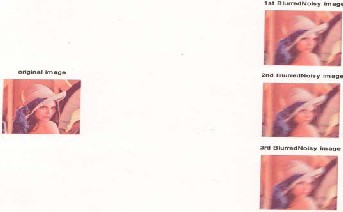
Fig9a: original Lena using Median filter with BSNR1-60dB for 1st channel, BSNR-2-40dB for 2nd channel and BSNR3-50dB for 3rd channel.
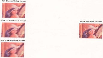
Fig9b: Restored Lena with ISNR1=3.3946dB for 1st channel, ISNR2=3.9642dB for 2nd channel and ISNR3=4.3261dB 3rd channel and MSE=203.
IJSER © 2015 http://www.ijser.org
International Journal of Scientific & Engineering Research, Volume 6, Issue 3, March-2015 556
ISSN 2229-5518
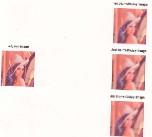
Fig10a: Original Lena using Zonal filter with BSNR1-60dB for 1st channel, BSNR-2-40dB for 2nd channel and BSNR3-50dB for 3rd channel at 0.25 Bit Rate.
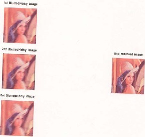
Fig10b: Restored Lena with ISNR1=4.1172dB for 1st channel, ISNR2=6.3681dB for 2nd channel and ISNR3=5.0599dB for 3rd channel and MSE=169.89.
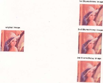
Fig11a: original Lena using zonal filter with BSNR1-60dB for 1st channel, BSNR2-40dB for 2nd channel and BSNR3-50dB for 3rd channel at 0.39 Bit Rate.
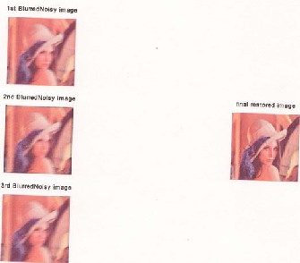
Fig11b: Restored Lena with ISNR1=4.0477dB for 1st channel, ISNR2=6.32633dB for 2nd channel and ISNR3=4.9955dB for 3rd channel and
MSE=173.2827.
IJSER © 2015 http://www.ijser.org
International Journal of Scientific & Engineering Research, Volume 6, Issue 3, March-2015 557
ISSN 2229-5518
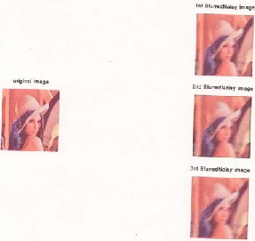
Fig12a: original Lena using zonal filter with BSNR1-60dB for 1st channel, BSNR2-40dB for 2nd channel and BSNR3-50dB for 3rd channel at 0.56 Bit Rate.
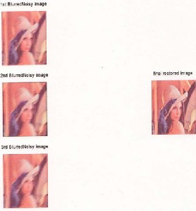
Fig12b: Restored Lena with ISNR1=3.6558dB for 1st
channel, ISNR2=5.9166dB for 2nd channel and
ISNR3=4.0685dB for 3rd channel and MSE=189.
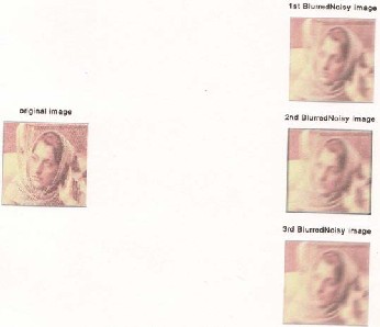
Fig 6a: original Barbara using Median filter with BSNR1-60dB for 1st channel, BSNR2-40dB for 2nd channel and BSNR3-50dB for 3rd channel.
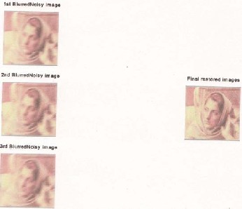
Fig6b: Restored Barbara with ISNR1=1.639dB for
1st channel, ISNR2=1.2486dB for 2nd channel and
ISNR3=1.2292dB for 3rd channel and MSE=498.
IJSER © 2015 http://www.ijser.org
International Journal of Scientific & Engineering Research, Volume 6, Issue 3, March-2015 558
ISSN 2229-5518
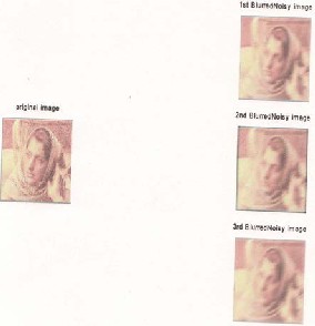
Fig 6.1a: original Barbara using zonal filter with BSNR1-60dB for 1st channel, BSNR2-40dB for 2nd channel and BSNR3-50dB for 3rd channel at 0.25 Bit Rate.
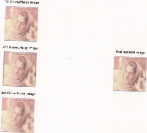
Fig6.1b: Restored Barbara with ISNR1=1.9930dB for 1st channel, ISNR2=2.8336dB for 2nd channel and ISNR3=1.5827dB for 3rd channel and MSE=459.
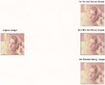
Fig6.2a: original Barbara using zonal filter with BSNR1-60dB for 1st channel, BSNR2-40dB for 2nd channel and BSNR3-50dB for 3rd channel at 0.39 Bit Rate.
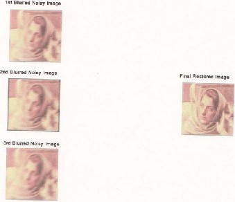
Fig 6.2b: Restored Barbara with ISNR1=1.1857dB
for 1st channel, ISNR2=3.0260dB for 2nd channel and
ISNR3=1.7729dB for 3rd channel and MSE=439
IJSER © 2015 http://www.ijser.org
International Journal of Scientific & Engineering Research, Volume 6, Issue 3, March-2015 559
ISSN 2229-5518
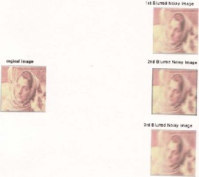
Fig6.3a: original Barbara using zonal filter with BSNR1-60dB for 1st channel, BSNR2-40dB for 2nd channel and BSNR3-50dB for 3rd channel at 0.56 Bit Rate.
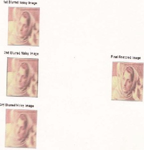
Fig 6.3b: Restored Barbara with ISNR1=1.2784dB for 1st channel, ISNR2=3.11dB for 2nd channel and ISNR3=1.8681dB for 3rd channel and MSE=430.
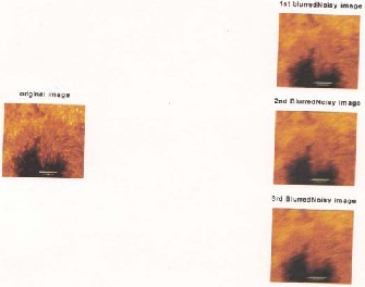
Fig6.4a: Subspot image using Median filter with BSNR1-60dB for 1st channel, BSNR2-40dB for 2nd channel and BSNR3-50dB for 3rd channel.
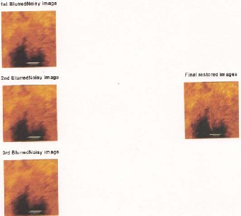
Fig6.4b: Restored sunspot image with ISNR1=1.2784dB for 1st channel, ISNR2=1.5833dB for 2nd channel and ISNR3=2.4537dB for 3rd channel
and MSE=271.
IJSER © 2015 http://www.ijser.org
International Journal of Scientific & Engineering Research, Volume 6, Issue 3, March-2015 560
ISSN 2229-5518
I. | Single-Input Multi-Output:- | Sunspot | I. Single-Input | Single-Output:- | Red |
Ima | ges (Zonal Filter 0.25BR) | Blood Cells (Median | Filter) |
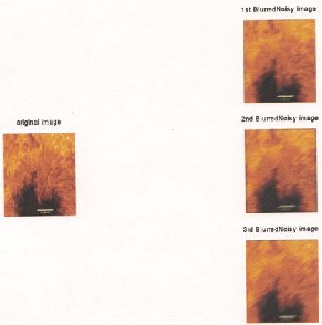
Fig 6.5a: Subspot Image using Zonal filter with BSNR1-60dB for 1st channel, BSNR2-40dB for 2nd channel and BSNR3-50dB for 3rd channel at 0.25
Bit Rate.
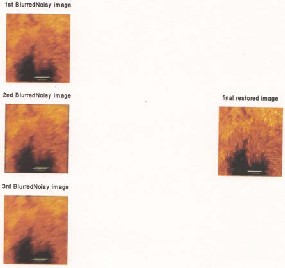
Fig 6.5b: Restored sunspot with ISNR1=2.1237dB for 1st channel, ISNR2=5.0268dB for 2nd channel and ISNR3=4.0810dB for 3rd channel and
MSE=184.0398.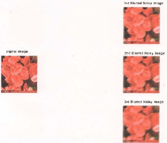
Fig6.6a: Electron Microscopic Image of Red Blood Cells using median filter with BSNR1-60dB for 1st channel, BSNR2-40dB for 2nd channel and BSNR3-
50dB for 3rd channel.

Fig6.6b: Restored Red Blood Cells with ISNR1=3.7035dB for 1st channel, ISNR2=3.4760dB for 2nd channel and ISNR3=3.2227dB for 3rd channel
and MSE=385.927.
IJSER © 2015 http://www.ijser.org
International Journal of Scientific & Engineering Research, Volume 6, Issue 3, March-2015 561
ISSN 2229-5518
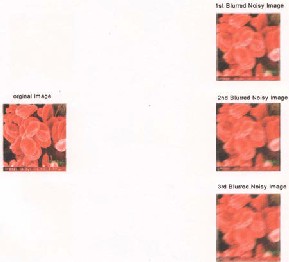
Fig6.7a: Electron Microscopic image of Red Blood Cells using zonal filter with BSNR1-60dB for 1st channel, BSNR2-40dB for 2nd channel and BSNR3-
50dB for 3rd channel.
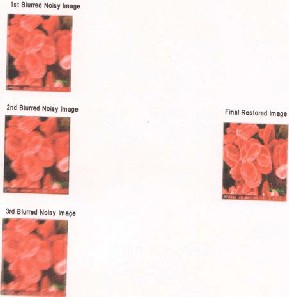
Fig6.7b: Restored Red Blood Cells with ISNR1=3.9184dB for 1st channel, ISNR2=6.3504dB for 2nd channel and ISNR3=5.6430dB for 3rd
channel and MSE=325.871.
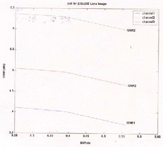
Fig6.8: Plot of ISNR’s for various Bit Rates for
Lena Image.
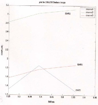
Fig.6.9: Plot of ISNR’s for various Bit Rates for
Barbara Image.
IJSER © 2015 http://www.ijser.org
International Journal of Scientific & Engineering Research, Volume 6, Issue 3, March-2015 562
ISSN 2229-5518
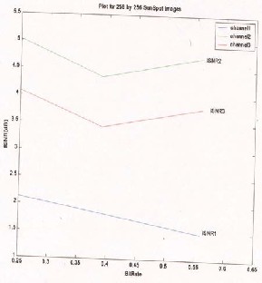
Fig 6.10: Plot of ISNR’s for various Bit Rates for
Sunspot Image.

Fig.6.11: Plot of ISNR’s for various Bit Rates for election microscopic red blood cells Image.
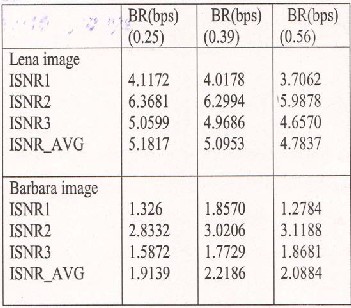
Table1: ISNR and Bit Rate values for Lena and
Barbara Image

Table2: ISNR and Bit Rate values for Sun Spot and
Red Blood Cell Image.
IJSER © 2015 http://www.ijser.org
International Journal of Scientific & Engineering Research, Volume 6, Issue 3, March-2015 563
ISSN 2229-5518
A simple and efficient method of restoring the multi-channel colored images using pre-processing zonal filtering in DCT domain and post processing deconvolution in time domain. The advantage of the proposed method is that the restoration is done under compression. Experimental results outperform recently used median filters, having better improvement in SNR showing consistent and stable performance across a wide range of blur and noise densities. Experimental results show that the quality of the restored image is good, only when the quantity of noise is less in case of standard median filters, whereas a zonal filter tries to remove the noise even in the worst case. The algorithm is efficient in terms of reduced computation of the order of 75 percent for lower bit rates.
[1] Gonzalez and Woods, “Digital Image
Processing” Fast Indian Reprint, 2002.
[2] Anil.K. Jain, “Fundamentals of Digital
Processing”. Prentice Hall of India-7 Reprint, 2001.
[3] V.K.Ananathashayana, “Image Representation using Number Theoretical Approach” PhD Thesis, University of Mysore,India.2001.
[4] A.K.Katsaggelos, Ed., Digital Image
Restoration. New York : Springer-Verlag, 1991.
[5] H.C.Andrews and B.R.Hunt, Digital Image
Restoration, Prentice-Hall, Inc., New Jersey, 1977.
[6] D.Kundur and D.Hatzinakos, “Blind image deconvolution revisited”, IEEE signal processing magazine, vol.13, no 3,, pp43-64, may 1996.
[7] How-lung and Kai-kuang Ma, “Noise Adaptive soft-Switching Median Filter”, IEEE Trans on Image Processing, vol.10,No 2, February 2001.
[8] Juan Liu and Pierre Moulin, “Complexity- Regularize Image Denoising”, IEEE Trans on Image Processing, Vol.10, No.6, June 2001.
[9] Georgios B.Giannakis and Robert W.Heath, “ Blind Identification of Multichannel FIR Blurs and Perfect Image Restoration, “IEEE Trans on Image Processing, Vol 9 No.11, November 2000.
[10] Deepa kundur, Dimtrios Hatzinakos, “Blind Image Restoration via Recursive Filtering using deterministic constrains”, IEEE Trans on Image Processing, Vol 46, No.2, February 1998.
[11] Vrhel and Unser, “Multichannel Restoration with a limited a prior information”, IEEE Trans on Image Processing, Vol 8, No.4, April 1999.
[12] Wirawan and Duhamel, “Multichannel High
Resolution Blind image Restoration”,
[13] Alex Acha and Shmuel Peleg, “Restoration of Multiple Images with Motion Blur in different directions.”
[14] Bogdan Smolka and Marek Szczepenski, “ Random walk approach to the problem of impulse noise reduction”.
[15] Yirong Shen and Rui Zhang, “ Image Blind
Deconvolution”.
[16] Hung-Ta Pai, “Multichannel Blind Image
Restoration” Ph.D Qualifying proposal.
IJSER © 2015 http://www.ijser.org