International Journal of Scientific & Engineering Research, Volume 4, Issue 9, September-2013 1101
ISSN 2229-5518
Mobile Phone Controlled Autonomous Robot
Anup Saha, Amit Saha, MD.Abdur Rahim, Pallab Sutradhar
Abstract— A robot is controlled by the remote control or it works autonomously. According to task of robot its control method is selected. But some military, industrial and household tasks require the both control methods. This study deals with the mobile phone controlled autonomous robot. Conventionally, wireless-controlled robots use RF circuits, which have the drawbacks of limited working range, limited frequency range and limited control. Use of a mobile phone for robotic control can overcome these limitations. It provides the advantages of robust control, working range as large as the coverage area of the service provider.
Keywords— Autonomous, DTMF, Infrared Sensor, Micro Controller 8051, Motor Driver L293D
—————————— ——————————
1. INTRODUCTION
HE existing demand of robots is increasing to do repetitive work and avoid life risk jobs, such as bomb diffusion, industrial operations, household tasks, etc.
This study based on mobile phone control system of autonomous robot [1].

Although the appearance and capabilities of robots vary vastly, all robots share the features of a mechanical, movable structure under some form of control. The control of robot involves three distinct phases: perception, processing and action [2]. Generally, the sensors mounted on the robot, processing is done by the on-board microcontroller or processor, and the task (action) is performed using motors or with some other actuators.

The concept of mobile phone controlled autonomous robot is control a robot by mobile phone along with put it into autonomous mode. By this control system as requirement of task it can control manually as well as it works autonomously by embedded artificial intelligence.
2. SYSTEM DESCRIPTION
2.1 Mobile Phone Control
————————————————
• Anup Saha has completed bachelor of engineering in Industrial and Production Engineering in Shahjalal University of Science and Technology, Bangladesh, PH-008801784152871. E-mail: anupipe@gmail.com
• Amit Saha has completed bachelor of engineering in Textile Engineering in City University, Bangladesh, PH-00919831292684. E-mail: amitece@ymail.com
• MD.Abdur Rahim is currently pursuing masters of engineering in
Industrial and Production Engineering in Bangladesh University of
Engineering and Technology, Bangladesh, PH-008801729584585. E-mail:
roney_ipe@ymail.com
• Pallab Sutradhar is currenlty working as IE & planning, Masco industrial
LTD, Bangladesh, PH-008801717793189. E-mail:pal.stdr@gmail.com

the mobile phone attached to the robot. In the course of a call, if any button is pressed, a tone corresponding to the button pressed is heard at the other end of the call. This tone is called
‘dual-tone multiple-frequency’ (DTMF) tone [3], [4], [5], [6], [7], [8], [9]. The robot perceives this DTMF tone with the help of the phone stacked in the robot.

The received tone is processed by the 8051 microcontroller with the help of DTMF decoder MT8870. The decoder decodes the DTMF tone into its equivalent binary digit and this binary number is sent to the microcontroller. The microcontroller is pre-programmed to take a decision for any given input and outputs its decision to motor drivers in order to drive the motors for forward or backward motion or a turn.
The mobile that makes a call to the mobile phone stacked in the robot acts as a remote. So this simple robotic does not require the construction of receiver and transmitter units.
DTMF signaling is used for telecommunication signaling over analog telephone lines in the voice-frequency band between telephone handsets and other communications devices and the switching centre [10]. The version of DTMF used for telephone tone dialing is known by the trademarked term Touch-Tone (cancelled March 13, 1984), and is standardized by ITU-T Recommendation Q.23. It is also known in the UK as MF4 [11].

DTMF assigns a specific frequency (consisting of two separate tones) to each key so that it can easily be identified by the electronic circuit. The signal generated by the DTMF encoder is a direct algebraic summation, in real time, of the amplitudes of two sine (cosine) waves of different frequencies, i.e., pressing ‘5’ will send a tone made by adding 1336 Hz and 770
Hz to the other end of the line. The tones and assignments in a
DTMF system are shown in Table 1.
The robot is controlled by a mobile phone that makes a call to
IJSER © 2013 http://www.ijser.org
International Journal of Scientific & Engineering Research, Volume 4, Issue 9, September-2013 1102
ISSN 2229-5518
TABLE 1
Tones and Assignments in a DTMF System
Frequencies | 1209 Hz | 1336 Hz | 1477 Hz | 1633 Hz |
697 Hz | 1 | 2 | 3 | A |
770 Hz | 4 | 5 | 6 | B |
852 Hz | 7 | 8 | 9 | C |
941 Hz | * | 0 | # | D |
2.2 Circuit Diagram
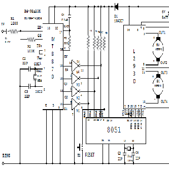
Fig. 1 Circuit Diagram of microcontroller 8051 based mobile phone controlled autonomous robot
2.3 Parts List
IC:
MT8870 DTMF decoder
8051 Microcontroller
L293D motor driver
74LS04 NOT gate
Resistors:
R1, R2 - 100 kilo-ohm
R3 - 330 kilo-ohm
R4-R8 - 10 kilo-ohm
Capacitors:
C1- 0.47 µF ceramic disk
C2, C3, C5, C6- 22pF ceramic disk
C4- 0.1 µF ceramic disk
Miscellaneous:
XTAL1- 3.57 MHz crystal
XTAL2- 12 MHz crystal
D1 – 1N4007 rectifier diode
S1- Push-to-on switch
Motor1, Motor2- 6V, 50-rpm geared
2.4 Circuit Description
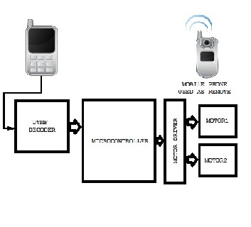
Fig. 2 Block diagram of the microcontroller-based mobile phone controlled autonomous robot
Fig. 2 shows the block diagram of the microcontroller- based mobile phone controlled autonomous robot. The important components of this robot are a DTMF decoder, microcontroller and motor driver.
An MT8870 series DTMF decoder is used here. All types of the MT8870 series use digital counting techniques to detect and decode all the 16 DTMF tone pairs into a 4-bit code output. The built-in dial tone rejection circuit eliminates the need for pre-filtering. When the input signal given at pin 2 (IN-) in single-ended input configuration is recognized to be effective, the correct 4- bit decode signal of the DTMF tone is transferred to Q1 (pin 11) through Q4 (pin 14) outputs.
IJSER © 2013 http://www.ijser.org
International Journal of Scientific & Engineering Research, Volume 4, Issue 9, September-2013 1103
ISSN 2229-5518
TABLE 2
DTMF Data Output
the outputs corresponding to their inputs are active.
Similarly, enable input EN2 (pin9) enables drivers 3 and 4.
2.5 Working
In order to control the robot, you need to make a call to the mobile phone attached to the robot (through mobile phone) from any phone, which sends DTMF tunes on pressing the numeric buttons. The mobile phone in the robot is kept in ‘auto answer’ mode.
TABLE 3
Actions Performed corresponding to the keys pressed
Table 2 shows the DTMF data output table of MT8870. Q1 through Q4 outputs of the DTMF decoder are connected to port pins PA0 through PA3 of 8051 microcontroller
after inversion by N1 through N4, respectively.
The NXP P89V51RD2 is a 40MHz, 5 Volt low-power 8051- based Microcontroller with 32 I/O lines, 3 Timers
/Counters, 9 Interrupts/4 priority levels, 64K+8K Flash, 1K RAM, SPI, Dual Data Pointers, 5-channel PCA [12], [13].
Outputs from port pins PD0 through PD3 and PD7 of the microcontroller are fed to inputs IN1 through IN4 and enable pins (EN1 and EN2) of motor driver L293D,
respectively, to drive two geared DC motors. Switch S1 is used for manual reset. The microcontroller output is not sufficient to drive the DC motors, so current drivers are required for motor rotation.
The L293D is a quad, high-current, half-H driver designed to provide bidirectional drive currents of up to 600 mA at voltages from 4.5V to 36V. It makes it easier to drive the DC motors. The L293D consists of four drivers. Pins IN1 through IN4 and OUT1 through OUT4 are input and output pins, respectively, of driver 1 through driver 4. Drivers 1 and 2, and drivers 3 and 4 are enabled by enable pin 1 (EN1) and pin 9 (EN2), respectively. When enable input EN1 (pin1) is high, drivers 1 and 2 are enabled and
IJSER © 2013
Now you may press any button on your mobile to perform actions as listed in Table 3. The DTMF tones thus produced are received by the mobile phone in the robot. These tones are fed to the circuit by the headset of the mobile phone. The MT8870 decodes the received tone and sends the equivalent binary number to the microcontroller. According to the program in the microcontroller, the robot starts moving.
When you press key ‘2’ (binary equivalent 00000010) on your mobile phone then the microcontroller output is
10001001 (binary equivalent). Port pins PD0, PD3 and PD7
are high. The high output at PD7 of the microcontroller
drives the motor driver (L293D). Port pins PD0 and PD3 drive motors Motor1 and Motor2 in forward direction (as per Table 3). Similarly, motors Motor1 and Motor2 move
http://www.ijser.org
International Journal of Scientific & Engineering Research, Volume 4, Issue 9, September-2013 1104
ISSN 2229-5518
for left turn, right turn, backward motion and
autonomous mode as per Table 3.
2.6 Autonomous Mode
In the autonomous mode the robot works with the instruction of embedded artificial intelligent in the microcontroller. In this study three IR pairs (infrared sensors) are used for avoiding the obstacle on the path of movement of robot. When the infrared [14] sensor detect any obstacle then artificial intelligent will decide the direction of robot movement.
2.6.1 IR pair circuit diagram
IC: LM324
IR Pair
2.6.3 IR pair circuit description
3-infrared sensors on the bottom for detect obstacle, when the sensors detected obstacle, output of comparator, LM324 is low logic and the other the output is high. Microcontroller 8051 and motor driver L293D were used to control direction and speed of motor [15].
2.6.4 Working of robot in autonomous mode
The robot moves forward autonomously until it detection any obstacle. 3-IR pairs are place in the bumper of robot to detect obstacle. If it detects the obstacle then the embedded artificial intelligence starts working and the robot works autonomously.
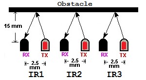
Fig. 4 IR pair placed in bumper of robot
TABLE 4
Actions Performed corresponding to response of Infrared sensors
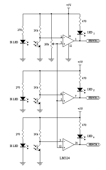
Fig. 3 IR pair of circuit Diagram
2.6.2 Parts lists
Resistors: 270, 470 ohm, 10 kilo-ohm
IJSER © 2013 http://www.ijser.org
International Journal of Scientific & Engineering Research, Volume 4, Issue 9, September-2013 1105
ISSN 2229-5518
After pressing 5 from mobile phone the robot go into autonomous mode. All the IR pairs start continuously checking for obstacle. The all possible situation of 3-infrared sensors and its corresponding action performed by the robot are shown in Table 4. When IR1 only detect obstacle the robot turns right, for IR3 turns left, for IR1and IR2 turns right, for IR2 and IR3 turns left. But some complicated situation (like IR1, IR2 and IR3 detect any obstacle) the robot start perceiving. 1st it turns left for a certain time and check for getting other situation if get then flow the instruction, otherwise it turns right until getting situation chance. If any IR pair does not get any obstacle it moves towards forward.
A small feature is included in this robot is LED head light of robot is automated. It is controlled by the LDR (Light Dependent Resistor) sensor. If LDR sense no light, it will send high logic to microcontroller and microcontroller on the LEDs. If LDR sense light, it will send low logic to microcontroller and microcontroller do the reverse work.
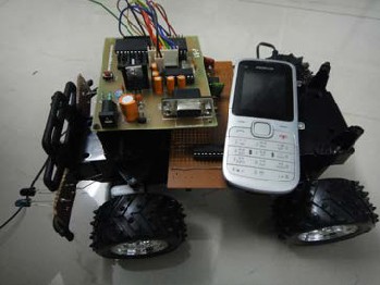
Fig. 4 Top view of mobile phone controlled autonomous robot
2.7 Future Improvement
More features can be added or can be replaced with the requirement of task.
Its embedded artificial intelligence can be improved with the requirement of task.
3. CONCLUSION
Mobile phone has become a most essential part of life. It is used not only for phone calls but also all the daily important
works. That’s why now-a-days mobile phone fills with lots of
features. So mobile phone control system of robot is a most flexible and convenient method for present world. In this study provides an overview how mobile phone control system is used for doing some specific work by manual control mode and some repetitive work by the autonomous mode of robot without being that particular place. It overcomes the limitations of remote controlled robot which is only capable to work by manual control and autonomous robot which is only works autonomously. However, there are lots of scopes to improve the ability of this system. It is undoubtedly true that this robot is a significant device in the remote areas where direct interference of human being is quite impossible.
REFERENCES
[1] Website: http://en.wikipedia.org/wiki/Autonomous_robot (last modified on 15 May 2013 at 01:36, Retrieved: 24 May 2013)
[2] Website:http://kitsnspares.com/admin/pdffiles/DTMF%20BASED%20
ROBOT%20CONTROL.pdf (Retrieved: 19 June 2013)
[3] Website: http://en.wikipedia.org/wiki/Dual-tone_multi-frequency
_signaling (last modified on 10 July 2013 at 19:58, Retrieved: 21 July
2013)
[4] T.L.V.V.Hemanth, P.Sasi kiran, A.Suresh. Industrial Application of DTMF Communication in Robotics. International Journal of Innovative Research and Development, 2 (4), April, 2013, 928-938, ISSN 2278-0211
[5] Rajesh Kumar, Manpreet Singh, Raman, Ashish Riyal. ROBAASTRA the Self Destructive Robot Control by Using DTMF Technology. International Journal of Engineering and Innovative Technology (IJEIT). 1(6), June 2012, 184-188, ISSN: 2277-3754
[6] Dhiraj Singh Patel, Dheeraj Mishra, Devendra Pandey, Ankit Sumele, Asst. Prof. Ishwar Rathod. Mobile Operated Spy Robot. International Journal of Emerging Technology and Advanced Engineering, 3(2), January 2013, 23-26, ISSN 2250-2459
[7] Pranoti P Mane, N. G. Bawane, Shahu T Jadhav. Mobile Operated Pelican Robot. National Conference on Innovative Paradigms in Engineering & Technology (NCIPET-2012)
[8] R. sharma, K. Kumar, and S. vig, “DTMF based remote control system”, IEEE international conference ICIT 2006, pp.2380-2383
December 2006
[9] Sabuj Das Gupta, Arman Riaz Ochi, Mohammad Sakib Hossain, Nahid Alam Siddique. Designing & Implementation of Mobile Operated Toy Car by DTMF. International Journal of Scientific and Research Publications, Volume 3, Issue 1, January 2013, ISSN 2250-
3153
[10] Awab Fakih, Jovita Serrao, Cell Phone Operated Robotic Car.
International Journal of Scientific & Engineering Research, ISSN
2229-5518.
[11] L. Schenker, "Pushbutton Calling with a Two- Group Voice- Frequency Code", The Bell System Technical Journal, 39(1), 1960,
235–255, ISSN 0005-8580
[12] Website: http://www.keil.com/dd/chip/3711.htm (Retrieved: 26 Jan
2013)
[13] Website:http://www.keil.com/dd/docs/datashts/philips/p89v51rd2.p df (Date of release: 01 March 2004, Retrieved: 26 July 2013)
[14] Website: http://en.wikipedia.org/wiki/Infrared (last modified on 26
July 2013 at 22:57, Retrieved: 24 Jan 2013)
IJSER © 2013 http://www.ijser.org
International Journal of Scientific & Engineering Research, Volume 4, Issue 9, September-2013
ISSN 2229-5518
1106
[15] Website:http://www. mytu tor ia!cafe.com/Miera con troIIer%20 Project
%20Thesis%20Robot%20Line%20Follower%201a.htm (Retrieved: 07 july 2013)
IJSER ©2013 http //www IJSer org