International Journal of Scientific & Engineering Research, Volume 6, Issue 2, February-2015 422
ISSN 2229-5518
Influences of Masonry Infill Wall, Tie Beam and
RCC Bracing on Soft Storey Mechanism
Prof. Prakarsh. Sangave1, Mr. Rajkumar Waghmare2, Mr. Nitin Hanamgaonswami2, Mr. Zaid Ahmed Kalyani2, Ms. Aishwarya Pawar2, Ms. Harsha Shinde2
ABSTRACT: The presence of infill wall in the building gives better behavior under lateral loads. Engineers believe that ignoring infill effect gives conservative design. For multistoried structures, the consideration of effect of bottom storey under seismic forces would be an important parameter. As per IS 1893 (Part-I) :2002 the columns and beams of the soft storey are to be designed for 2.5 times the storey shear and moments calculated under the seismic load of a bare frame ( i.e. without considering infill effect). In this paper model is studied to investigate the magnification factor for various load combinations considering peripheral masonry infill wall only, peripheral masonry infill wall along with tie beams and RCC X bracings under seismic effect. The Equivalent diagonal strut method is used to calculate the width of infill strut by FEMA approach. The R.C.C. building model (P+7) has been prepared using ETAB software. The Seismic Coefficient Method has been performed for the analysis of various models. The results of investigations and their conclusions are discussed below.
Index Terms: Base shear, Displacement, Equivalent diagonal strut, Infill wall, Tie beam, R.C.C. X-Bracing, Load combinations, Magnification factor, Soft
Story.
1 INTRODUCTION
—————————— ——————————
urrently India is a rapidly urbanizing country which leads to acquisition of land under different mega structures. The Reinforced Concrete (RC) Frame building is one of the under category field which is the current scope of construction in India. Now days due to the limitations of the horizontal development of the building, it has become necessary to grow vertically (Multi-storey, Sky scrapers etc.). Hence, due to higher height of the building, the effect of earthquake plays a dominant role for mechanism of structural parameters. One of the major considerations in high rise building is the ‘Soft storey’. According to Indian standard code 1893 (Part-I) : 2002 clause 4.20 page no.10 a soft storey is one in which the lateral stiffness is less than 70 percent of that in the storey above or less than 80 percent of the average lateral stiffness of the three storeys above. The soft storey may be in the form of vehicle parking (Refer Fig.1), for Commercial shop purpose, Intermediate soft storey for firefighting purpose
etc.
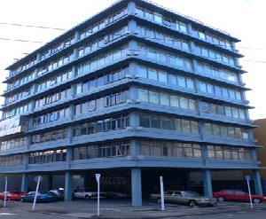
Fig.1.Typical Image of Soft Storey
The significant use of this storey is functionally, but from a seismic performance point such a building is considered to have increased vulnerability. From the past earthquakes it is found that major failure occurred in the soft storey floor. Therefore it is necessary to withstand the soft storey under lateral loads with sufficient strength and stiffness and adequate ductility. The soft storey can be strengthened by using the structural and/or non-structural element like provision of RCC bracings, steel bracings, shear wall, peripheral tie beam, provision of brick masonry infill panels or combinations. According to Indian standard code 1893 (Part-I) : 2002 clause 7.10.3 (a) page no.27 states that, the columns and beams of the soft storey are to be designed for
2.5 times the storey shear and moments calculated under
the seismic loads of a bare frame ( i.e. without considering infill effect). The factor 2.5 is called as magnification factor. The magnification factor is supposed to be compensating for stiffness discontinuity. The F. Demir’s and M. Sivri (2002) approach is used to calculate the masonry infill strut width. Indian standard code is silent about considering the provision of peripheral infill effect, peripheral infill effect along with tie beams or RCC bracings in soft storey for magnification factor.
2 OBJECTIVE OF THE WORK
The objective behind the work descript below:
i) To check the applicability of magnification factor 2.5 with considering the provisions like peripheral infill effect, peripheral infill effect with peripheral tie beams and peripheral infill effect with peripheral RCC bracings in OGS.
ii) To check the applicability of magnification factor 2.5 with various load combinations given in IS code.
IJSER © 2015 http://www.ijser.org
International Journal of Scientific & Engineering Research, Volume 6, Issue 2, February-2015 423
ISSN 2229-5518
3 VARIOUS LOAD COMBINATIONS
As per IS code 1893 (Part-I): 2002 clause 6.3.1.2 page no.13
1) 1.5 (DL + LL) 2) 1.2 (DL + LL ± EQx)
3) 1.2 (DL + LL ± EQy) 4) 1.5 (DL ± EQx)
5) 1.5 (DL ± EQy) 6) 0.9 DL ± 1.5 EQx
7) 0.9 DL ± 1.5 EQy
By considering the above load combinations the
Magnification factor has been investigated.
4 STRUCTURAL FRAMING
The presence of only masonry infill walls, masonry infill wall along with Tie beam or RCC X-bracing in a framed building not only enhance the lateral stiffness but also alters the transmission of forces in beams and columns as compared to the bare frame. In a bare frame, the resistance to lateral forces is due to the development of bending moments and shear force in the beam and column through the rigid jointed action.
5 FRAMING SYSTEM CONSIDERED FOR ANALYSIS
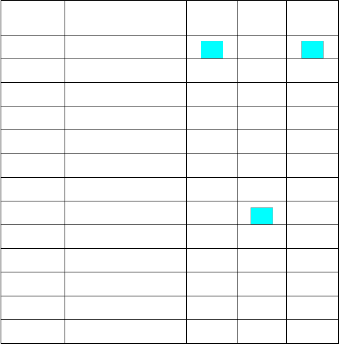
For the analysis purpose four models are prepared (see
Table 1) namely,
TABLE 1 METHODOLOGY
TABLE 3 COLUMN GROUPING
Group | Location | Column No. |
G - I | Corner Columns | C1, C4, C21, C24 |
G - II | Peripheral Columns | C2-3, C5, C8-9, C12- 13, C16-17, C20, C22-23 |
G - III | Central Columns | C10-11, C14-15 |
Fig.3.Plan of Building
6 PARAMETRIC CONSIDERATIONS FOR BUILDING MODEL
For the analysis purpose the following structural and seismic data has been considered (See Table 4)
TABLE 4 DESCRIPTION OF BUILDING MODEL
The bottom storey Columns & beams being grouped according to their position as follows (See Table 2 and 3, refer Fig.3),
TABLE 2 BEAM GROUPING
Group | Location | Beam No. |
G - I | Corner Beams | B1 , B3 , B16 , B18-19 , B23 , B34 , B38 |
G - II | Peripheral Beams 1 | B2 , B4 , B6-7 , B9-10 , B12 - 13 , B15 , B17 |
G - III | Peripheral Beams 2 | B20-22 , B24 ,B28-29 , B33 , B35-37 |
G - IV | Central Beams | B5 , B8 , B11 , B14 , B25-27 , B30-32 |
IJSER © 2015 http://www.ijser.org
International Journal of Scientific & Engineering Research, Volume 6, Issue 2, February-2015 424
ISSN 2229-5518
(Continuous…….)
R1 = MII / MI Pu = Axial Force
R2 = MIII / MI Myy = Moment about yy-axis
R3 = MIV / MI Mxx = Moment about xx-axis
7.1 The magnification factors of Soft Storey Columns
7.1.1 For Group I column
TABLE 5 AXIAL FORCE RATIOS
7 Results
For various forces acting on bottom storey column cross section as shown in Fig.4 under various load combinations for R1, R2 and R3 are tabulated and graphically represented as below,
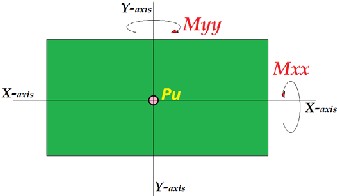
Fig.4.Forces Acting on Column Cross Section
1.8
1.6
1.4
1.2
1
0.8
0.6
0.4
0.2
0
R1 R2 R3
1 2 3 4 5 6 7 8 9 10 11 12 13
Load Combination
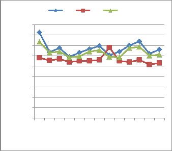
Fig.9.Axial force ratio
IJSER © 2015 http://www.ijser.org
International Journal of Scientific & Engineering Research, Volume 6, Issue 2, February-2015 425
ISSN 2229-5518
TABLE 6 MOMENT RATIO ABOUT YY-AXIS
TABLE 7 MOMENT RATIO ABOUT XX-AXIS
Load
SR.NO. combinations R1 R2 R3
1 1.5(DL+LL) 3.78 0.89 1.48
2 1.2(DL+LL+EQx) 0.23 0.62 0.2
3 1.2(DL+LL-EQx) 1.34 0.67 0.2
4 1.2(DL+LL+EQy) 1.18 1.03 1.17
5 1.2(DL+LL-EQy) 1.26 1.06 1.19
6 1.5(DL+EQx) 1.28 0.64 0.18
7 1.5(DL-EQx) 1.33 0.67 0.18
8 1.5(DL+EQy) 1.04 0.88 1.01
9 1.5(DL-EQy) 0.46 0.38 0.44
10 0.9DL+1.5EQx 1.35 0.54 0.14
11 0.9DL-1.5EQx 1.32 0.65 0.16
12 0.9DL+1.5EQy 1.23 0.98 1.17
13 0.9DL-1.5EQy 1.32 1.01 1.2
2
1.8
1.6
1.4
1.2
1
0.8
0.6
0.4
0.2
0
R1 R2 R3
1 2 3 4 5 6 7 8 9 10 11 12 13
Load Combination
4
3.5
3
2.5
2
1.5
1
0.5
0
R1 R2 R3
1 2 3 4 5 6 7 8 9 10 11 12 13
Load Combination
Fig.10.Moment ratio about yy-axis
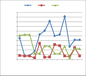
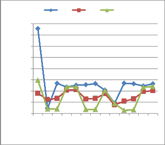
Fig.11.Moment ratio about xx-axis
IJSER © 2015 http://www.ijser.org
International Journal of Scientific & Engineering Research, Volume 6, Issue 2, February-2015 426
ISSN 2229-5518
7.1.2 For Group II columns
TABLE 8 AXIAL FORCE RATIOS
SR.NO.
Load combinations
SR.NO.
TABLE 9 MOMENT RATIO ABOUT YY-AXIS
Load
R1 R2 R3
1 1.5(DL+LL)
2 1.2(DL+LL+EQx) 1.03 1.21 1.18
3 1.2(DL+LL-EQx) 1.19 1.05 1.04
4 1.2(DL+LL+EQy) 1.45 1.32 1.21
5 1.2(DL+LL-EQy) 1.45 1.63 1.28
6 1.5(DL+EQx) 1.48 1.27 1.23
7 1.5(DL-EQx) 0.98 1.06 0.65
8 1.5(DL+EQy) 1.56 1.36 1.37
9 1.5(DL-EQy) 1.17 1.05 1.03
10 0.9DL+1.5EQx 1.76 1.4 1.53
11 0.9DL-1.5EQx 1.31 1.04 1.2
12 0.9DL+1.5EQy 1.8 1.55 1.53
13 0.9DL-1.5EQy 1.18 1.01 1.05
combinations
1 1.5(DL+LL) 0.85 0.15 1.07
2 1.2(DL+LL+EQx) 0.51 0.06 0.62
3 1.2(DL+LL-EQx) 0.51 0.06 0.71
4 1.2(DL+LL+EQy) 1.02 0.54 1.27
5 1.2(DL+LL-EQy) 1.05 0.58 1.61
6 1.5(DL+EQx) 1.13 1.11 0.63
7 1.5(DL-EQx) 1.14 1.13 0.71
8 1.5(DL+EQy) 0.99 0.63 0.47
9 1.5(DL-EQy) 1.02 0.55 0.49
10 0.9DL+1.5EQx 1.78 0.7 0.64
11 0.9DL-1.5EQx 0.65 0.072 0.71
12 0.9DL+1.5EQy 0.9 0.54 1.48
13 0.9DL-1.5EQy 0.8 0.53 0.97
2
1.8
1.6
1.4
1.2
1
0.8
0.6
0.4
0.2
0
R1 R2 R3
1 2 3 4 5 6 7 8 9 10 11 12 13
Load Combination
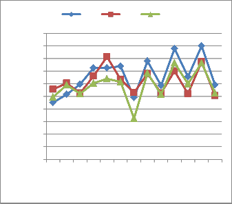
Fig.12.Axial force ratio
2
1.8
1.6
1.4
1.2
1
0.8
0.6
0.4
0.2
0
R1 R2 R3
1 2 3 4 5 6 7 8 9 10 11 12 13
Load Combination
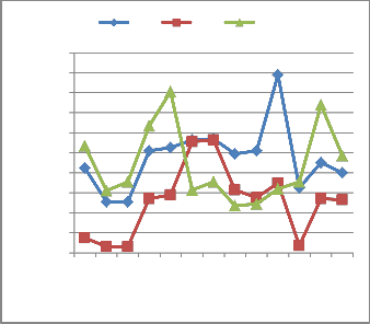
Fig.13.Moment ratio about yy-axis
IJSER © 2015 http://www.ijser.org
International Journal of Scientific & Engineering Research, Volume 6, Issue 2, February-2015 427
ISSN 2229-5518
TABLE 10 MOMENT RATIO ABOUT XX-AXIS
7.1.3 For Group III columns
TABLE 11 AXIAL FORCE RATIOS
3
2.5
2
1.5
1
0.5
0
R1 R2 R3
1 2 3 4 5 6 7 8 9 10 11 12 13
Load Combination
1.2
1
0.8
0.6
0.4
0.2
0
R1 R2 R3
1 2 3 4 5 6 7 8 9 10 11 12 13
Load Combination
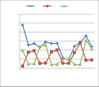
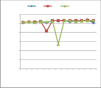
Fig.14.Moment ratio about xx-axis
Fig.15.Axial force ratio
IJSER © 2015 http://www.ijser.org
International Journal of Scientific & Engineering Research, Volume 6, Issue 2, February-2015 428
ISSN 2229-5518
TABLE 12 MOMENT RATIO ABOUT YY-AXIS
TABLE 13 MOMENT RATIO ABOUT XX-AXIS
1.2
1
0.8
0.6
0.4
0.2
0
R1 R2 R3
1 2 3 4 5 6 7 8 9 10 11 12 13
Load Combination
1.8
1.6
1.4
1.2
1
0.8
0.6
0.4
0.2
0
R1 R2 R3
1 2 3 4 5 6 7 8 9 10 11 12 13
Load Combination
Fig.16.Moment ratio about yy-axis
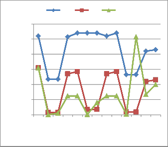
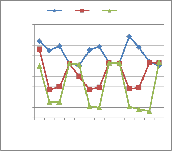
Fig.17.Moment ratio about xx-axis
IJSER © 2015 http://www.ijser.org
International Journal of Scientific & Engineering Research, Volume 6, Issue 2, February-2015 429
ISSN 2229-5518
7.2 The Magnification factors for Soft Storey Beams
7.2.1 Shear Force
TABLE 12 SHEAR FORCE RATIOS OF OPEN GROUND STOREY BEAMS
1.6
1.4
1.2
1
0.8
0.6
0.4
0.2
0
R1 R2 R3
G - I G - II G - III G - IV Group of Beams
R1 R2 R3
5
4
3
2
1
0
G - I G - II G - III G - IV
Group of Beams
Fig.18.Moment ratios of open ground storey beam
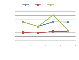
7.3 Storey Base Shear and Displacement
7.3.1 Base Shear
TABLE 13 BASE SHEARS OF DIFFERENT MODELS
Fig.19.Shear force ratios of open ground storey beams
7.2.2 Moments
TABLE 11 MOMENT RATIOS OF OPEN GROUND STOREY BEAMS
3000
2500
2000
1500
1000
500
0
EQX EQY
Bare Infill Infill + Tie Infill+bracing
Different Frames
Fig.20.Base shear of different models
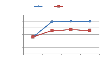
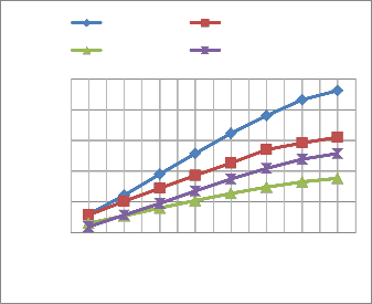
7.3.2 Displacement
7.3.2.1 X-Direction
TABLE 14 DISPLACEMENTS IN X-DIRECTION OF DIFFERENT MODELS
Storey | Bare | Infill | Infill + Tie | Infill +bracing |
S - 1 | 4.4 | 5.4 | 2.36 | 1.49 |
S - 2 | 9.64 | 10.5 | 4.7 | 5.32 |
IJSER © 2015 http://www.ijser.org
International Journal of Scientific & Engineering Research, Volume 6, Issue 2, February-2015 430
ISSN 2229-5518
Bare Infill
Infill + Tie Infill+bracing
50
40
30
20
Bare Infill 10
Infill + Tie Infill+bracing 0
40
35
30
S - 1 S - 2 S - 3 S - 4 S - 5 S - 6 S - 7 S - 8
Stories
25
20
15
10
5
0
S - 1 S - 2 S - 3 S - 4 S - 5 S - 6 S - 7 S - 8
Stories
Fig.21.Displacement in X-direction of different models
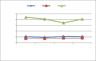
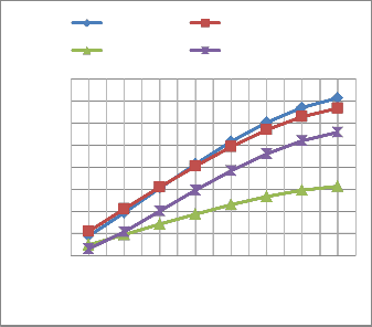
7.3.2.2 Y-Direction
TABLE 15 DISPLACEMENTS IN Y-DIRECTION OF DIFFERENT MODELS
Fig.22.Displacement in Y-direction of different models
8 Results and Discussion
The results of the present study show that peripheral masonry infill wall along with tie beam and RCC X-bracing has very important effect on structural behavior under seismic forces.
8.1 For bottom storey columns the following Magnification Factor has been investigated for various load combinations and is discussed below.
8.1.1 From above analysis of group I column following points are observed.
R1) Max. Axial force Ratio is 1.65 for comb. 1.5(DL+LL), max. Moment Ratio about y-axis is 1.83 for comb. 0.9DL-
1.5EQx and max. Moment Ratio about x-axis is 3.78 for comb. 1.5(DL+LL).
R2) Max. Axial force Ratio is 1.36 for comb. 1.5(DL+EQy), max. Moment Ratio about y-axis is 0.68 for comb.
1.5(DL+EQx) and max. Moment Ratio about x-axis 1.06 for
comb. 1.5(DL+EQx).
R3) Max. Axial force Ratio is 1.47 for comb. 1.5(DL+LL), max. Moment Ratio about y-axis is 1.05 for comb.
1.2(DL+LL-EQx) and 1.2(DL+LL+EQy) and max. Moment
Ratio about x-axis 1.48 for comb. 1.5(DL+LL).
8.1.2 From above analysis of group II columns following points are observed.
R1) Max. Axial force Ratio is 1.8 for comb. 0.9DL+1.5EQy, max. Moment Ratio about y-axis is 1.78 for comb.
0.9DL+1.5EQx and max. Moment Ratio about x-axis is 2.39
for comb. 1.5(DL+LL).
IJSER © 2015 http://www.ijser.org
International Journal of Scientific & Engineering Research, Volume 6, Issue 2, February-2015 431
ISSN 2229-5518
R2) Max. Axial force Ratio is 1.63 for comb. 1.2(DL+LL- EQy), max. Moment Ratio about y-axis is 1.13 for comb.
1.5(DL-EQx) and max. Moment Ratio about x-axis 1.4 for
comb. 0.9DL-1.5EQx.
R3) Max. Axial force Ratio is 1.53 for comb. 0.9DL+1.5EQx and comb. 0.9DL+1.5EQy, max. Moment Ratio about y-axis is 1.61 for comb. 1.2(DL+LL-EQy) and max. Moment Ratio about x-axis 1.54 for comb. 0.9DL+1.5EQy.
8.1.3 From above analysis of group III columns following points are observed.
R1) Max. Axial force Ratio is 1.08 for comb. 0.9DL+1.5EQy, max. Moment Ratio about y-axis is 1.08 for comb.1.5 (DL+EQx), comb.1.5 (DL-EQx), comb. 1.5(DL+EQy) and comb.0.9DL+1.5EQx and max. Moment Ratio about x-axis for comb.1.5 (DL+LL).
R2) Max. Axial force Ratio is 1.07 for comb. 0.9DL+1.5EQy, max. Moment Ratio about y-axis is 0.62 for comb.
1.5(DL+LL) and max. Moment Ratio about x-axis 1.32 for
comb. 1.5(DL+LL).
R3) Max. Axial force Ratio is 1.07 for comb. 0.9DL-1.5EQy, max. Moment Ratio about y-axis is 1.03 for comb.0.9DL-
1.5EQx and max. Moment Ratio about x-axis 1.08 for comb.
0.9DL-1.5EQy.
8.2 The magnification factor of beams adjacent to RCC X- bracings gets increased for shear force.
9 Conclusions
As per IS 1893-2002 (Part I) clause 7.8.2, the Magnification factor 2.5 is a very conservative factor for design purpose of all columns and beams, especially for low rise building and even it is conservative for high rise building.
From above investigation done on this Magnification factor
2.5 considering different load combinations, some modified
values other than 2.5 are as follows. For columns, grouping
is done according to their location mentioned above and respective values are as follows.
1) When the Peripheral masonry infill wall is provided in soft storey, the Magnification factor for corner columns 3.7, for peripheral column 2.30 and for central column 1.85.
factor for corner columns 1.48, for peripheral column 1.60 and for central column 1.10.
4) When the Peripheral masonry infill wall along with Tie beam is provided in soft storey, the Magnification Factor for beams is less compared to frames without tie-beams.
5) When masonry infill wall along with tie-beam is provided in soft storey, the base shear value is more in both directions compared to frames without tie-beams.
6) Displacement in both directions is minimized when masonry infill along with tie-beam is provided compared to frames without tie-beams.
REFERENCES
[1] Mario Paz, Structural Dynamics: Theory and Computation.
[2] Pankaj Agarwal and Manish Shrikhande, Earthquake Resistant design of Structure.
[3] S.K Duggal “Earthquake Resistant Design of Structure”
[4] Criteria of Earthquake Resistant Design Of Structure, IS code 1893
:2002, Bureau of Indian Standards, New Delhi.
[5] Saurabh sing, Saleem akhtar, Geeta batham,”evaluation of seismic behaviour for multistoried RC Moment Resisting Frame with Open Frist Storey”,international journal of current engineering and technology,vol.4(2014).
[6] Bhagavathula Lohita, S.V.Narsi Reddy, ”Earthquake Resistant Design of Low rise Open ground Storey Framed Building”, International journal of modern engineering research, issued 6. Vol.4. (june 2014)
[7] Wakchaure M.R, Ped S.P, “ Earthquake AnalysisnOf high Rise Building With and Without In Filled walls”, International journal of engineering and Innovative Technology, Issue 2,vol.2, August
2012
[8] Krushna B. Avhad, “Seismic analysis of High Rise Open Ground Storey Framed Building”, International journal of recent Technology and engineering, Issue 4, Vol.3, September 2014.
[9] Mohammad h jinya,v.r.patel,” Analysis of R.C frame With and Without masonary infill wall with different stiffness with outer central opening”, International Journal of Reasearch In engineering and Technology, Issue 06,vol. 03,jun 2014.
[10] Narendra Pokar, Prof. B.J Panchal, Prof. B.A. vays ,“ Small Scale Modelling on Effect of Soft Storey”, International Journal of Advanced Engineering and Technology, July 2013
[11] N. Sivakumar, S Karthik, S. saravanan, C.K.Shidhardhan
,”Seismic Vulnerability of Open Ground Floor Columns in Multistorey Buildings”, International Journal of Scientific Engineering and Reasrch, Issue 3, Vol. 1,Nov 2013.

1
2) When the Peripheral masonry infill wall along with Tie beam is provided in soft storey, the Magnification factor for corner columns 1.36, for peripheral column 1.63 and for central column 1.32.
3) When the Peripheral masonry infill wall along with RCC X-bracing is to be provided in soft storey, the Magnification
Assosiat Professor, Department of Civil Engineering
Nagesh Karajagi Orchid College of Engineering and Technology, Solapur-
413002, Maharashtra, India.
2UG Student, Department of Civil Engineering
Nagesh Karajagi Orchid College of Engineering and Technology, Solapur-
413002, Maharashtra, India.
IJSER © 2015 http://www.ijser.org