
International Journal of Scientific & Engineering Research, Volume 6, Issue 5, May-2015 1543
ISSN 2229-5518
Improving the storage capacity of
Removable Media Storage Devices
Ndubuisi P.D.I, Eneh I.I., Alor M.O.
1: Electrical/Electronic Engineering Dept, Akanu Ibiam Federal Polytechnic, Uwana, Afikpo, Ebonyi
State, Nigeria
2&3: Electrical and Electronic Engineering Dept, Enugu State University of Science and Technology,
Enugu, Nigeria
—————————— ——————————
This work “Influence of Numerical aperture Disk Media Production” is about the applications of intelligent technique in the control of a modeled disk media device that can be produced for the recording and retrieval of data.
A Disk is a flat shaped plate of material specifically produced to act as a medium for the storage and retrieved of information (Dan Keen, 2014). Such electronic system devices are classified as disk media. Thus disk media relates to those information storage and retrieval system devices that can be utilized in audio, video, and data applications. Prior to the advent of computer, most information storage devices were in the form of
reels that are used in film projections or telecine broadcast machines, video home sets (VHS) and audio cassettes. However, with the emergence of personnel computer, there has been a significant change in the requirements for removable media storage system devices (RMSDs). The first ever removable media storage device is the magnetic floppy disk. Others include the solid state Flash drive and the Hard disk drive.
(a)Floppy disk (b) Flash drive
(c) Hard disk drive
(Keen 2014).
IJSER © 2015 http://www.ijser.org
International Journal of Scientific & Engineering Research, Volume 6, Issue 5, May-2015 1544
ISSN 2229-5518
Subsequent developments in the RMSD are informed by improved storage and retrieval parameters including capacity, speed, access time, data transfer rate, data availability, backward compatibility, durability and convenience. Consequently the compact disk (CD) was introduced. The CD has a maximum storage capacity of 793 megabytes. The digital versatile disk (DVD) followed with an improved storage capacity of 15.9 Giga bytes. Presently, the fluorescence multilayer disk (FMD) or the constellation three dimensional disk (C3D) are being developed. It has a capacity of one Tetra bytes.
The technology applicable in the read and write data on RMSD includes; magnetic format that uses magnetic particles and magnetic fields, optical formats that uses laser light and optical sensors, magnetic optical and magneto-optical hybrid that uses a combination of magnetic and optical properties to increase storage capacities, holographic format that can write and read one million bits of data in a single flash of light. Figure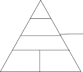
3 shows the traditional classification of data storage devices.
Primary
RAM
Solid state
Secondary
Magnetic disk
commonly called Secondary Storage devices. Typical devices in this category are the Floppy disk, Flash drives and Hard disk drives. At the bottom of the hierarchy are tertiary storage devices. These groups include magnetic tapes, Optical tapes, Optical disk and Holographic storage technologies.
The technology of RMSD is still evolving. With the rapid advancement of internet and computer technology, the demand of massive and inexpensive data storage tools has increased dramatically. For the last twenty years, optical disks, in particular read-only compact disks (CDs) and digital versatile disks (DVDs) have enabled us to replicate massive amount of data in an inexpensive removable format. Optical disks are also popular as recording devices in the formats of compact-disc-recordable (CD-R) and compact- disk-rewritable (CD-RW). Other formats, such as DVD-R and DVD-RW, are just emerging into the market of massive data storage. As the optical data storage technology evolves, the capacity of an optical disk increases (Tieke et al. 1999). The CD and DVD devices use the mechanism of far-field single-layer recording. A more advanced technology, which uses multiple layers on a single disk, is called volumetric bit-wise optical data storage. This new technology is expected to extend the capacity of optical disks in the orders of magnitude beyond what is found in CD and DVD (Ahmed etal, 2007).
This paper presents the characterization of optical systems that can be used for volumetric bit-wise optical data storage. One promising direction to
Magnetic tape
Optical disk
Tertiary
satisfy these requirements with low cost systems is the use of optical volumetric multi-layer disk media. The application of intelligent technique in disk media production can go a long way in improving the quality of removable media storage
Fig.3: Storage hierarchy showing the traditional classification of devices for data storage
At the top of the hierarchy is the primary storage. Belonging to this classification is the Random Access Memory (RAM) used for caches and main memory. Typical RAM technologies are Static RAM and Dynamic RAM. Below RAM is Solid State memory and Magnetic disk. They are
devices (RMSDs) in areas of storage capacity, data transfer rate, access speed, access time, data availability, backward compatibility and durability.
2. THEORY
Optical Disc Technology.
In optical recording, a non-contact optical head
uses a laser beam to store information on a disc surface by creating pits in the surface material.
IJSER © 2015 http://www.ijser.org
International Journal of Scientific & Engineering Research, Volume 6, Issue 5, May-2015 1545
ISSN 2229-5518
LASER which stands for Light Amplification by the Stimulated Emission of Radiation is monochromatic, directional, coherent and collimate. It is characterized with one wavelength. It is emitted as a relatively narrow beam in a specific direction. The light from a laser is in phase both in time and space. Laser operates within the infrared, visible and ultraviolet bandwidth of the electromagnetic spectrum, corresponding to a wavelength range of 100 nanometer to 1 Pico meter.
The radiation energy of laser is given by E=MV2 and is inversely proportional to wavelength; where E is Radiation Energy, M is the mass of the laser and V is the velocity of Laser propagation. Laser light consists of photons, each with discrete quantum of energy proportional to their wavelength. For an electron to be freed from a surface it would need a photon with enough energy to overcome the energy that bound it to the atom. Making light brighter or reducing the wavelength would supply more photons. Light with a shorter wavelength consisted of higher energy photons that could supply the needed energy to free electron. The portion of the electromagnetic spectrum where lasers operate are infrared, visible, and ultraviolet radiation (Parthenopoulos et al,1989). Table1 shows the wavelength of Laser Radiations.
Radiations.
The energy produced by laser at its incidence object is greater at lower wavelength. The physical size of a laser beam depends on the material used for light emission, the output power and the pulse duration of the beam. Lasers use two layers of semiconductor substances such as gallium arsenide. Optical discs are called write once, read many (WORM) device. The beam width is the single most important characteristic of a laser beam profile. At least five definitions of beam width are in common use: D4σ, 10/90 or 20/80 knife-edge,
1/e2, FWHM, and D86. The D4σ beam width is the
ISO standard definition and the measurement of
the M² beam quality parameter requires the
measurement of the D4σ widths.
The other definitions provide complementary information to the D4σ and are used in different circumstances. The choice of definition can have a large effect on the beam width number obtained, and it is important to use the correct method for any given application. The D4σ and knife-edge widths are sensitive to background noise on the detector, while the 1/e2 and FWHM widths are not (S. Ravi, 2013)). The fraction of total beam power encompassed by the beam width depends on which definition is used. The M2 parameter is a measure of beam quality; a low M2 value indicates good beam quality and ability to be focused to a tight spot.The surface of a cross section of an optical disk track on which laser modulated signal is incident on is as shown in fig 4.
Land Pit
Thin metal Layer![]()
![]()
Plastic substrate Transparent dielectric![]()
![]()
![]()
![]()
![]()
![]()
![]()
![]()
IJSER © 2015 http://www.ijser.org
International Journal of Scientific & Engineering Research, Volume 6, Issue 5, May-2015 1546
ISSN 2229-5518
Aluminum reflector
Focus lens
Disc Optical track
Laser
beam
modulator optics
Input
transducer Data detector

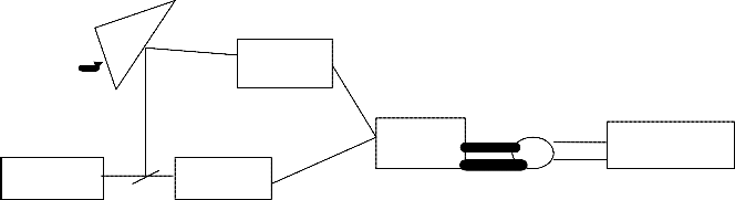
Fig. 5: Block diagram of optical disc technology (Chervenak 1994).
The Fig.5 illustrates in a block form, how data is recorded or retrieved from disk track. Figs.4 and
5.are used to illustrate optical disc technology. During writing, in response to an electrical input signal, a highly focused laser beam melts a small region of the metal layer opening a hole or pit. Data are thus encoded and stored as alternating regions of pits and lands. The encoded binary data (bits) in the form of pits (binary value of 0 or off, due to lack of reflection when read) and lands (binary value of 1 or on, due to a reflection when read) on a special material (often aluminum) on one of its flat surfaces. The encoding material sits atop a thicker substrate (usually polycarbonate) which makes up the bulk of the disc and forms a dust defocusing layer. The encoding pattern follows a continuous, spiral path covering the entire disc surface and extending from the innermost track to the outermost track.
The data is stored on the disc with a laser or stamping machine, and can be accessed when the data path is illuminated with a laser diode in an optical disc drive which spins the disc at speeds of about 200 to 4,000 RPM or more, depending on the drive type, disc format, and the distance of the
read head from the center of the disc (inner tracks are read at a higher disc speed). The pits or bumps distort the reflected laser light, hence most optical discs characteristically have an iridescent appearance created by the grooves of the reflective layer. During reading, a lower intensity, un- modulated laser beam is reflected off the surface of the disc. A photo detector interprets information stored on the disc by detecting differences in reflectivity between pits and holes on the thin metal layer. The encoding may be likened to a pit representing a zero and a land representing a one. On an optical disc, data may be stored in a single track or as a series of concentric circular tracks. The system works with three servo mechanisms; one for tracking, second for focusing the laser beam, and the third for controlling the speed of rotation of the disc to ensure that the data transfer rate is constant.
Holographic storage technology.
A hologram is a block or sheet of photosensitive material which records the interference of two light sources. To create a hologram, laser light is first split into two beams, a source beam and a reference beam. The source beam is then
IJSER © 2015 http://www.ijser.org
International Journal of Scientific & Engineering Research, Volume 6, Issue 5, May-2015 1547
ISSN 2229-5518
manipulated and sent into the photosensitive material. Once inside this material, it intersects the reference beam and the resulting interference of laser light is recorded on the photosensitive material, resulting in a hologram. Once a hologram is recorded, it can be viewed with only the reference beam. The reference beam is projected into the hologram at the exact angle it was projected during recording. When this light hits the recorded diffraction pattern, the source beam is regenerated out of the refracted light. An exact copy of the source beam is sent out of the hologram and can be read by optical sensors (Heanue ,1994)). Precise laser equipment is used at the factory to create the hologram. A recording material which can recreate recorded images out of natural light is used, and not a high-tech equipment to view the information stored in the hologram.
Holographic Data Storage has advantages over conventional storage methods in the following areas;
Data is stored in all three dimensions of the material and not just the surface, read/write speeds are also much higher since data is written and read out as 2D digital or analogue images in a
3D volume rather than a bit stream and the bit rate
error is also decreased considerably because error
causing factors such as scratches, dust, etc tend to
affect the surface only and since a hologram is
recorded as a complex interference pattern in the bulk of the material, these affects are limited.
(i) Holographic images
Holographic images interfaces empower operators to enter commands and data into a wide range of electronic equipment by simply passing a finger through holographic images of what would otherwise be the keys of a keypad or keyboard, appearing to float in the air at a convenient location in front of the equipment. An infrared sensor scans the plane of those images to detect the intrusion of a finger into the desired portion of those images, identifies which number or symbol has been selected and transmits that selection to the equipment's internal software, much the same way pressing a button on any ordinary keypad would.
Holographic images solve many problems posed by conventional, tactile keypads and keyboards, particularly those regularly subjected to contaminants, customer abuse, dirt, moisture, temperature fluctuations and shock.
Like an optical technology, it works with three servo drive mechanism; one for tracking or layer selection, the second for actuating the lens system and the third for controlling the spindle of the disc which spins between 200 and 4000 rpm. Figs.6 and
7 illustrates the holographic technology.
Mirror
Page addressing
Laser beam
Optics
Crystallite array
Detector array
IJSER © 2015 http://www.ijser.org
International Journal of Scientific & Engineering Research, Volume 6, Issue 5, May-2015 1548
ISSN 2229-5518
Disc w/Multiple Layers
--------------------------------------------------------------------------------------
--------------------------------------------------------------------------------------
--------------------------------------------------------------------------------------
Spindle
Spherical aberration
corrector Dichotic
Actuator
Mirror
Laser
Filler
Laser
Driver
Detector
Pre
Amp
Signal
Processor
Data
Cntrl
Layer
Selector
Servo

Solid Immersion Lens (SIL), Volumetric Storage
Optics and Volumetric Storage Media
The solid immersion lens (SIL) is currently being
developed as a near-field data storage technique
(Mizuno et al. 2001), which utilizes evanescent energy to greatly increase NA and produce extremely small optical spots. A typical arrangement for the SIL system is shown in Fig.
2.7. A SIL, which is an image-centric hemispherical
lens with high refractive index, is placed in near
contact with the recording medium. Light from a laser passes through the beam splitter and is focused near the bottom of the SIL by an objective lens. The size of the light spot is smaller than the laser wavelength. The evanescent field generated from the bottom of the SIL is coupled into the recording medium, which leads to a small data mark. Hence, the data capacity is greatly increased on each layer.
IJSER © 2015 http://www.ijser.org
International Journal of Scientific & Engineering Research, Volume 6, Issue 5, May-2015 1549
ISSN 2229-5518
A second way to increase the data capacity is to use volumetric optical data storage technology. Currently, volumetric technology is divided into two research areas, which are holographic optical data storage and volumetric bit-wise optical data storage. Since the invention of holography (Gabor
1948), people have tried tirelessly to develop
optical memory based on the holographic optical interference technique. Chen et al (1968) first proposed to use LiNbOS as the holographic storage medium. In holographic storage, data sets are transferred to and from storage material as 2-D images composed of thousands of pixels, with each pixel representing a single bit of information. However, no one location in the medium is responsible for storing that one bit; each bit is distributed throughout the recorded interference fringes.
Bit-Wise Volumetric Optical Data Storage
There are three categories of material that have
been used in bit-wise volumetric optical data
storage technology. The first category is refractive-
index-change material, which consists of photopolymer, photorefractive, and photo chromic material. The second category is fluorescent material. The third category is material with Super- Rens structure.
The ultrahigh density multi-layer disk recording by two photon absorption Model is assumed. In this model, a high Numerical Aperture (NA) objective lens (NA>1) with a long working distance (>100mm) together with a multilayer volumetric optical media provides an important direction towards the realization of ultra high density multi-layer recording by two-photon absorption. A high NA objective lens decreases bit size, increases the volumetric density, and reduces the recording laser power requirements for a given recording speed.
For Increasing Disk Capacity, the parameters required for a 2-photon 3-D optical data storage disk, are:
(i) The disk.
The Disc is circular in shape. The surface area of a circular disk is πr2; where r is the radius. In a disk media, there is a limited portion in which data can be recorded for retrieval. This boundary is defined by the difference between the maximum recording surface area and the minimum recording surface area.
The maximum recording surface
2
Amax
area,
= πrmax
(1)
3. METHODOLOGY
Development of a model for optical data storage
The minimum recording surface area,
2
capacity.
Amin
= πrmin
(2)
IJSER © 2015 http://www.ijser.org
International Journal of Scientific & Engineering Research, Volume 6, Issue 5, May-2015 1550
ISSN 2229-5518
The portion of the disk on which data can be stored
Slayer
is the layer separation.
S = Amax −
Amin or
Tdisk
S = πr
2 − πr
2 or S
= π (r
2 − r
G2e)nerally,
should be smaller than the
max
min
(3)
max
minworking distance of the objective lens.
Substituting 7 into 8, the storage capacity
Where “r” is the radius of the circle.
Ctotal
=
(ii) The optical system.
[π (0.61λ ) 2
NA /1.22λ ]N
layer
The area raw capacity of the disk is proportional to the size of Numerical aperture (NA),
and inversely proportional to the bit size defined by lpit×wpitch in the X-Y plane.
The total area of raw capacity is expressed as:
(9)
For Ultra high density multi-layer disk readout;
During readout, fluorescence is emitted in
4π radians. The objective lens collects only a
small portion of the fluorescence. The substrate of
Careal
π (r 2 max −
![]()
=
×
r 2 min )
NA
the disk is
n1 = 1.492.
The critical angle affects
lbit
wpitch
the maximum solid angle that can be collected.
Total collection efficiency is the ratio of the
(4)
r in equation 3 is equal to the beam radius of the
(Wo )
collected solid angle to 4π
radians:
NA
laser
Wo
= radius of disk
(r )
times wavelength =
n collection
= (1 −
1 = (
n1

) 2 ) / 2
0.61λ
(5)
Also, the bit size of a laser modulated data defined
(10)
1pit
by
× Wpitch
is equal
2
NA =
n1 sin θ
lens.
to beam quality parameter (M
≥ 1) times
n = refractive index in image space. Θ =
wave length =1.22λ
(6)
By substituting equations 5 and 6 in equation 4,
marginal ray angle in image space.
Application of Fussy system on optical data storage capacity.
Careal
= π (0.61λ )2 NA / 1.22λ
(7)
For the intelligent system for disc media production controller design, there are two inputs
and one output that are designed through the
The volume raw capacity of a 2-photon 3-D optical
data storage disk
toolbox. The inputs are numerical aperture and number of disc layers. The output is the disc
Ctotal
is:
= Careal
* N layer
capacity.
Nlayer =
of layers.
Tdisk
Tdisk
/ Slayer
(8)
is the number
4. DATA PRESENTATION AND ANALYSIS
Comparison of disk media devices.
Table 2 below shows the evaluation of some parameters of removable media storage devices.
is the thickness of the disc;
IJSER © 2015 http://www.ijser.org
International Journal of Scientific & Engineering Research, Volume 6, Issue 5, May-2015 1551
ISSN 2229-5518
Table 2: Evaluation of removable media storage devices.
s/n | Name of disk media | Size | Read and write principle | Maximum storage capacity | Others |
1. | Floppy disk | 8’, 5’, 3.5’ | Magnetic | 1.44megabyte | Low speed, not durable |
2. | Hard disk drive | Solid state | 40 megabyte | No rotation | |
3. | Flash drive | 2’ | Same | 8 gigabyte | Convenience, no rotation |
4. | Compact disk | 120mm diameter,1.2mm thickness | Optical | 7.93 megabyte | Speed, durability, convenience |
5. | Digital versatile disk | Same | Same | 15.9 megabyte | Same |
6. | Fluorescent multilayer disk | Same | Same | 1 terabyte | Same |
Table 3: The percentage storage capacity of RMSD
S/N | RMSD | Maximum storage capacity | Percentage storage capacity |
1 | Floppy disk | 1.44 MB | 0.0001 % |
IJSER © 2015 http://www.ijser.org
International Journal of Scientific & Engineering Research, Volume 6, Issue 5, May-2015 1552
ISSN 2229-5518
2 | Hard disk drive | 40 MB | 0.0039 % |
3 | Flash drive | 8 GB | 0.7813 % |
4 | Compact disk | 7.9 MB | 0.0008 % |
5 | Digital versatile disk | 15.9 GB | 1.5528 % |
6 | Fluorescent multilayer disk | 1 TB | 97.66 % |
Total | 1.02394937 TB | 99.9998 % |
Demonstration of the model on optical data storage by simulation.
Equations 7 or 9 and 10 of the model were used in MATLAB simulation. Below are the model parameters for the 2-photon 3-D optical data storage disk.
Radius of beam width r = 0.61λ/NA Wavelength (λ) =460nm
Numerical aperture (NA) = 0.2 to 1.8.
Pulse repetition rate = 76MHz
Pulse width = 200 per second
Bit length per bit = 1.22 λ/NA
Bit size = I bit x w pitch = 1.22 x λ
r = (r2max - r2min)
π ==22/7
n1=1.492
No of Layers =10
For equation 9, the simulated data from the
numerical aperture used is as shown in table 4.
Table 4: Variation of Storage Capacity with increasing NA.
efficiency is also shown in table 5. It is evident from that table that the maximum efficiency occupant is at the numerical aperture of 1.4. Beyond that point the collection efficiency becomes complex.It is therefore at this point where numerical aperture is 1.4 that puts a limit to the achievable storage capacity of 6.1732TB.
Table 5: Variation of Collection Efficiency with increasing NA.
For equation 10, the simulated data from each of the numerical aperture used for collection
5. ANALYSIS
Effect of Numeric Aperture on storage capacity.
Using table 4, the graph of area capacity (storage capacity) versus Numerical aperture was plotted as shown in fig below
IJSER © 2015 http://www.ijser.org
International Journal of Scientific & Engineering Research, Volume 6, Issue 5, May-2015 1553
ISSN 2229-5518
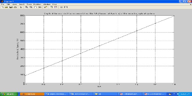
Fig.15: Storage Capacity and NA plot for disk
It can be seen clearly that as Numerical aperture increases the storage (surface) capacity of the Disc increases. In order to increase the volumetric capacity (aerial density, and volumetric density) a tradeoff between high NA and lens working distance is considered, as well as recording laser power requirements that are now examined.
6. CONCLUSION
Influence of the numerical aperture on a 3-D multi- layer optical data storage system is analyzed based on simulation results. With a Numeric Aperture of
0.2 up to 1.4, there is remarkable increase in storage capacity. Further increase in Numeric
Aperture leads to further increase in the storage capacity. However, the collection efficiency increase is synonymous with increase in storage capacity up to a Numeric Aperture of 1.4. Beyond this value of Numeric Aperture, the collection efficiency becomes complex. This provides a limit to the possible storage capacity realizable with Fluorescent Multilayer Disk. There is not yet an established factor that can limit the storage capacity with increase in the number of disk layer except perhaps the penetration ability of the laser beam. A high NA objective lens decreases bit size,
layer separation, and increases the volumetric capacity.
REFERENCES
Ahmed, Ali and Robert, de Souza (2007) “Modeling and Simulation of Hard Disk Drive final
Assembly using HDD template”; Proceedings of
2007 Winter Simulation Conference, Delhi,
Chen, F. S., Lamacchia, J. T., and Fraser D. B., (1968) "Holographic storage in lithium niobate," Appl.
Phys. Lett. 13, 223-225
Dan Keen (2014) “What are Computer Storage Devices? Htt:/www.ehow.com/video, Retrieved on 18th
IJSER © 2015 http://www.ijser.org
International Journal of Scientific & Engineering Research, Volume 6, Issue 5, May-2015 1554
ISSN 2229-5518
February.
Fuji, H., Tominaga, J., Men, L., Nakano, T.,
Katayama, H., and Atoda, N., (2000) "A near-field recording and readout technology using a
metallic probe in an optical disk," Jpn. J.
Appl. Phys., Part 1,
39, pp. 980-98.
Gabor, D., (1948), "A new microscopic principle," Nature, 161, 777-778.
Gopal Dhanya, (2012) “Fluorescent Multilayer
Disk”,R7A Roll No. 22, CSE Paper Presentation.
Haskal, H. M., (1979) "Laser recording with truncated Gaussian beam," Appl. Opt. 18, 2143-
2146
Heanue J. F., Bashaw M. C., and Hesselink L., (1994) "Volume holographic storage and retrieval of
digital data," Science 265 (5173), pp. 749-752
Ishikawa, M., Kawata, Y., Egami, C., Sugihara, O.,
and Okamoto, N., (1998)"Reflection-type confocal readout for multilayered optical memory,
“Optics Letters, Vol. 23, No. 22, pp. 1781-1783,.
Kawata, Y., Ueki, H., Hashimoto, Y., and Kawata,
S., (1995) "Three-dimensional optical memory
with a photorefractive crystal," Appl. Opt. Vol.
34, No. 20 pp. 4105-4109,
Miller, T., Butz, J., and Milster, T. D., (2003) "Novel
method for tracking in homogeneous volumetric
media," ODS 2003 pp. 187-189.
Parthenopoulos, D. A., and Rentzepis, P. M., (1989)
"Three-dimensional optical storage memory,"
Science 245 (0), pp. 843-845
Rakuljic, G. A., Leyva, V., and Yariv, A., (1992)
"Optical data storage by using orthogonal wavelength-multiplexed volume holograms,"
Optics Letters, Vol. 17, No. 20 pp. 1471-
1473,.
Ravi Kumar S.K, Arora, D. Kanji, G.K.Mehta (1999) Radiation Effects and Defects in
Solids:Incorporating Plasma Science and Plasma Technology, Online Platform for Taylor & Francis
Group, Volume 147, Issue 3, 1999
Strickler J. H., and Webb, W. W., (1993) "3-D optical data storage by two-photon point excitation,"
Advanced Materials 5 (6) pp. 479-481,.
Tieke, B, M.Dekker, N. Pfeffer, R. van Woudenberg, G. Zhou, and L Ubbens, (1999) "High
data-rate phase-change media for the digital video recording system," in Proc. SPIE joint Int. Symp.
Optical Memory and Optical Data Storage,
3864, 200-202.
Vikas Tripathi (2010) “Holographic data storage”, Seminar Project, United Institute of Technology,
Allahabad.
Vishnu K. Vardhan Redddy (2012) “Fluorescent Multilayer Disk”, A Seminar report, Department of Computer Science and Engineering, DRK
Institute of Science and Technology, Delhi.
Walker, E. P., Feng, W., Zheng, Y., Zhang, H.,
Mccormick, F. B., and Esener, S., (2002) "3-D
parallel readout in a 3-D multilayer optical data
storage system," ODS 2002, pp. 147-149.
Zhang H., Walker E. P., Feng W., Zhang Y., Dvomikov A. S., Esener S. and Rentzepis P. M., (2000)
"Multi-layer optical data storage based on two- photon recordable fluorescent disk media," Eighteenth
IEEE Symposium on Mass Storage System, 2000
pp 225-236
IJSER © 2015 http://www.ijser.org
International Journal of Scientific & Engineering Research, Volume 6, Issue 5, May-2015 1555
ISSN 2229-5518
IJSER © 2015 http://www.ijser.org