OVERVIEW OF THE SYSTEM
The Wireless Nomadic Bank Surveillance System operates on the platform of three technologies namely the GPS, the GSM and the IP Surveillance. The system comprises of three units namely the asset tracking unit, the panic button unit and the IP surveillance unit.
The panic button system, placed beneath the cashiers coun- ters is a Machine-to-Machine (M2M) application that uses the GSM technology as the communication network for data transmission. The circuitry of the panic button consists basical- ly of a GSM module and a microcontroller. To control the op- eration of the GSM module in the panic button system, anoth- er GSM module system incorporated into the nomadic system via the serial port is used. This is done by the use of instruc- tions known as AT commands in a HyperTerminal window. The microcontroller is therefore programmed to control mes- saging to and from the GSM module. These panic buttons are placed such that the cashier or banker can access them easily. On the occurrence of a bank robbery, when the button is pressed, the microcontroller will detect the action and send a signal to the GSM module which will forward an SMS mes- sage from the Nomadic system to the nearest already assigned police station and other security agencies for necessary action. The IP surveillance unit is used to remotely monitor the bank- ing hall through covert surveillance IP cameras placed in the banking hall. These cameras allow the banking hall and other priority locations to be monitored remotely from the nomadic monitoring unit. The dummy cameras also play a significant role in this unit. These dummy cameras look just like real sur- veillance cameras and are very difficult to differentiate by a criminal or intruder. Dummy cameras, however are more ef- fectively used to complement real cameras by making an area look to have more surveillance than it actually does.
For this system, the placement of dummy cameras helps to achieve two major goals. First, the fear of these cameras placed in strategic locations deters intruders who don’t want to risk being caught on tape. This level of criminals are people who want to make a fast break to enrich themselves and most often target a limited amount of money especially from the cashiers. Secondly, in the case of more sophisticated robbers who usual- ly attempt to have a higher target of money by breaking into the vault of the bank, their first action on gaining entrance into the banking hall is to disable all cameras. The deployment of dummy cameras therefore trick or fool these robbers into be- lieving that they have disabled all the cameras whilst surveil- lance by covert cameras is still on-going with the nomadic monitoring unit. To serve as a redundancy to the panic but- ton system in terms of broadcasting alert messages to con- cerned personnel and security agencies, a web application is developed using PHP, JavaScript and MySQL for managing the video feeds and forwarding SMS alert messages to special- ly assigned security agencies saved in the database in the case of a robbery.
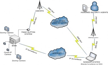
Fig. 1: Architectural diagram showing the operation of the Panic Button System and the IP Surveillance System
Furthermore, the asset tracking unit is an embedded sys- tem that is placed in certain packs of currency (money tracker) and bags (bag tracker). This minute unit with rechargeable low-power batteries is used for locating the whereabouts of the robbers after a robbery. The GPS receiver module interacts with the satellite in space and receives data i.e. location infor- mation in form of radio waves.
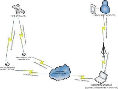
Figure 2: Architectural diagram of the Money/Bag Tracker
All of the three units are monitored by the Nomadic moni- toring unit which is a mini computer system specially assem- bled for this purpose. The system is used to query the bag and money tracker for the present location. The Google earth soft- ware installed on the nomadic system is used to map the re- ceived National Marine Electronics Association (NMEA) for- mat to the actual position. It also serve as a redundancy to the panic button system, a web application is developed using PHP, JavaScript and MySQL for managing the video feeds and forwarding SMS alert messages to specially assigned security agencies saved in the database in the case of a robbery.
HARDWARE SYSTEM DESIGN
The design of the hardware part of the system is presented in this section. The choice of components, the justification for such choice and the circuit design is also presented therein.
Power Source
Due to the desired minute form factor and the mobile nature of the system, a direct current voltage supply source is uti- lized. A Lithium Ion rechargeable battery of 3.3 – 5.0V is used in this circuit design due to its energy conserving power and efficiency. A charging circuit is built into the circuit so as to charge the battery when needed. To conserve the battery, the device is programmed to lie in a sleep mode until it is ‘trig- gered’ by a sent SMS.
Microcontroller
The microcontroller is the heart of the device. It is a single chip containing a microprocessor, memory (RAM and ROM), A/D converter, input/output ports, timers and serial ports. It is designed for embedded control applications and its prime function is to control a machine or system using a fixed pro- gram stored in the ROM of the system. The program does not change over the lifetime of the system.
PIC18F2520 is chosen because it is ideal for applications re- quiring cost-effective, low-power solutions with a robust pe- ripheral set in a small package. It is an 8-bit Microcontroller that has 32 Kilobytes of Flash Program Memory (ROM), a RAM size of 1.5kB, 4 timers and 25 I/O lines. Its maximum CPU speed is 40 MHz with an operating voltage range of 2V to 5.5V [13].
Furthermore, the microcontroller which is at the core of the circuit and serves as the driver of the circuit needed to be pro- grammed so that it can perform the function of controlling the behavior and actions of the GPS and GSM receivers. In-Circuit Serial Programming (ICSP), a method of directly program- ming PIC microcontrollers is used to program the microcon- troller through a programmer. The program is written in as- sembly language. Figure 3 below represents the operational flow process of the programmed microcontroller.
The hardware interfaces for GPS units are designed to meet NMEA requirements. The NMEA protocol which is commonly used is NMEA0183 protocol. GPS sentences begin with the following specifications: $GPGGA, $GPGSA, $GPGSV,
$GPRMC, $GPVTG, $GPMSS and $GPZDA. The choice for this work (and most commonly used) is the $GPRMC (acro- nym for Recommended Minimum Specific GPS/Transit data).
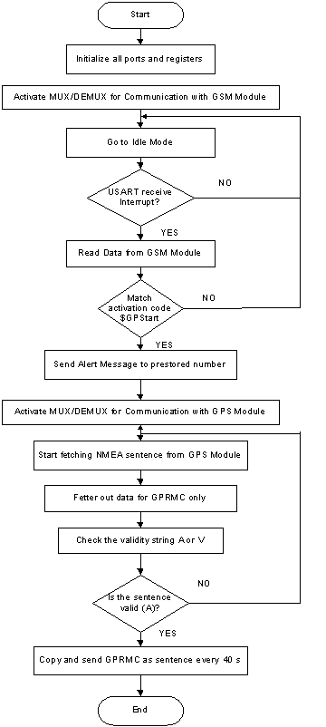
Fig. 3. Operational Flow Process of the Programmed Microcontroller
GPS/GSM Module
The hub of data communication in this system is carried out by wireless communication control terminals that use GSM modules for reliable data transfer with the support of instruc- tions known as AT commands. The GPS receiver module in- teracts with the satellite in space and receives data i.e. location information in form of radio waves. The hardware interfaces for GPS units are designed to meet NMEA requirements. The NMEA protocol which is mostly used is NMEA 0183 protocol. This data is communicated to the GSM modem by the micro- controller. The GSM modem enables the transmission of the location data through the GSM network to pre-assigned au- thorized phone numbers and the nomadic system. Like the mobile phones, a GSM modem requires a SIM card from a wireless operator to enable it transfer data through the opera- tor’s network.
For this system, the SIM 908 is chosen because it is a hybrid of the GSM/GPRS/GPS modules. It also has a small package size of 30x30x3.2mm. This helps to reduce cost and saves extra PCB cost of the system. Also, with advanced, innovative de- sign, it can reduce sleep mode power consumption, providing a power saving of up to 40% compared to current industry averages. SIM908 is integrated with high performance GSM/GPRS engine and an internal GPS engine. The GSM/GPRS engine is a quad-band GSM/GPRS module that works on GSM 850MHz, EGSM 900MHz, DCS 1800MHz and PCS 1900MHz frequencies [14].
THE 74HC138 De-Multiplexer
This device serves as an intermediary between the microcon- troller, the GPS module and the GSM module. Considering the pin layout of the microcontroller, it has one transmit (TX) pin and one receive (RX) pin. TX is the port through which data is sent out to other devices while RX is the port or line through it receives data from other devices Nevertheless, there is need for the transmit (TX) pin to communicate with both the receive (RX) pins of the GPS and GSM modules. This device is there- fore used to de-multiplex the serial output data into a multi- lined data transmitted from the USART pins of the Microcon- troller Unit. The 74HC138 devices are designed to be used in high-performance memory-decoding or data-routing applica- tions requiring very short propagation delay times. It is a 3- line to 8-Line Decoder/Multiplexer.
The 74HC151 Multiplexer
This device also serves as an intermediary between the micro- controller, the GPS module and the GSM module. The TX data line of both the GSM and GPS modules need to communicate with the RX data line of the microcontroller hence the need for a multiplexer.
HARDWARE IMPLEMENTATION
In our system, PROTEUS ISIS is used to create the circuit de- sign and simulate it. Furthermore, PROTEUS ARES is used to create the PCB layout. The circuit design of the money tracker is shown in Fig 4, Fig. 5 shows the implemented money track-
er and Fig. 6 shows the Nomadic Monitoring Unit.
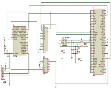
Fig. 4. Circuit diagram of the money tracker
Furthermore, the actual implementation of the money tracker was also achieved. The electronic components with functionalities already discussed in the section above are used to achieve this.
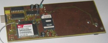
Fig. 5. Actual implementation of money circuit
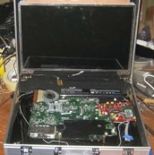
Fig. 6. Assembling of Nomadic Monitoring Unit
SOFTWARE DESIGN AND IMPLEMENTATION
The software designed in this system has the sole purpose of interfacing the bank with security agencies. The occurrences in the banking hall are monitored remotely from video feeds from surveillance cameras placed in the bank from the No- madic system and in the occurrences of any emergency, a bank robbery in this case, alert messages are sent to the closest security agencies as already stored in the database of the no- madic system. The architecture of a database backed web ap- plication usually varies depending on the desired functionali- ty of the built web application. The Web database application built herein has a database structure as shown in the Fig.7 below.
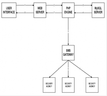
Fig. 7. The Web Application Architecture
The tools, applications and programming language used in designing this system include HTML, Cascade Style Sheet 3 (CSS3), Adobe Photoshop, Apache Web server, PHP5.2.5, MySQL 2.0 to house the backend database, SMS Gateway and Windows 7 operation system for development. The login is the first point of contact, where an existing user is granted access and any unrecognized user is denied access. After ac- cess has been granted to the user, there is an opportunity for users to add cameras, connect to cameras, manage mobile numbers, manage short messages and view the log of connect- ed persons.
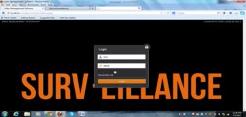
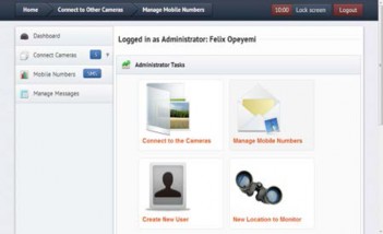
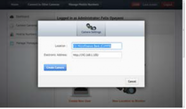
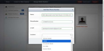
Fig. 8. Screenshots from Surveillance Software
RESULTS AND DISCUSSION
As already explained, the money tracker circuit is mostly in an idle mode in order to conserve the battery power. On the occur- rence of an emergency, the money tracker is re-awakened by sending an SMS with ‘$GPStart’ as the content to the Subscriber Identity Module (SIM) number of the GSM module. Thus, the GPS receiver on the money tracker begins to receive GPS co- ordinates of the present location from the GPS satellite. The GSM module on the same money tracker sends the co-ordinates to the GSM module on the nomadic system. In summary, while the microcontroller is the brain of the system and the GSM mo- dem controlled by AT commands facilitates data transmission over GSM network while the GPS module provides the location date. The nomadic monitoring system consists basically of the GSM Modem, RS232 cable and the computer hardware. The GSM modem receives the message through GSM while the message is transferred to the computer through the serial port. The received GPS co-ordinates are presented in MS Hyper- Terminal as shown Fig. 9 below.
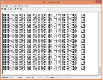
Fig. 9. GPS coordinates from HyperTerminal
Furthermore, the log of the received GPS coordinates is used to trace the path of travel of the money tracker circuit when in motion. This is done with the use of Franson GPSGate software; a web-based GPS tracking platform with functions such as GPS simulation and logging and connecting a GPS to Google Earth among others. This software installed on the nomadic monitoring system acquires the GPS coordinates reaching the GSM module interfaced with the receiver, logs it continually and connects dynamically with Google Earth to provide a trace of the path of the tracked item. During test, Figure 10 displays the path of travel on Google Earth.
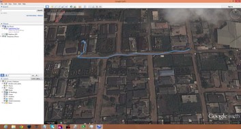
Fig. 10. Illustration of path of travel of money tracker