Introduction
The need for sensors has grown rapidly in recent years for industrial control, automation and consumer applications. In modern measurement and control system, a great number of sensors collect the information about the process available in the system being monitored. They usually provide analogue information on the system being monitored through signal conditioning circuits connected to a processor. The processor interprets the information, makes appropriate decisions most likely in conjunction with higher-level control, and implements those decisions via actuators [1].
In 1982, Ko and Fung introduced the term “intelligent transducer” [2]. An intelligent or smart transducer is the integration of an analog or digital sensor or actuator element, a processing unit, and a communication interface. In case of a sensor, the smart transducer transforms the raw sensor signal to a standardized digital representation, checks and calibrates
the signal, and transmits this digital signal to its users via a standardized communication protocol [3]. In case of an actuator, the smart transducer accepts standardized commands and transforms these into control signals for the actuator. In many cases, the smart transducer is able to locally verify the control action and provide a feedback at the transducer interface. With the advent of modern microcontrollers it became possible to built low-cost smart transducers by using commercial-off-the-shelf microcontrollers that provide a standard communication interface, such as a UART. Thus, the usage of smart transducers can become a cost decreasing factor for building embedded control systems [4]. A Universal Transducer Interface (UTI), presented by Meijer, Frank and Goes in 1997, is a low-cost high-performance interface between sensing elements and microcontrollers or DSPs. This interface, which is read out by a microcontroller, services the following sensor elements: capacitors, platinum resistors, thermistors, resistive bridges and potentiometers. The circuit has been fabricated in a 0.7 µm CMOS process [5]. The universal sensor interface chip (USIC) represents a complete signal processing capability for data acquisition systems designed to support a wide range of sensor applications. Offers high performance with flexibility and requires only a small number of external components for many applications [6]. A smart sensor module includes a microcontroller and signal conditioning circuit [7]. The signal conditioning integrated circuit is mixed signal application specific integrated circuit (ASIC) incorporating an instrumentation amplifier, offset correction, sensitivity correction, low pas filtering, an ADC, temperature sensor, digital I/O interface, crystal oscillator. The smart sensor module allows very precious calibration of sensor, signal processing capabilities, decision-making capability and serial interface capabilities [8]. In 2002, Xiujun Li; Frank, van de Goes; Meijer; Rolf de Boer presented universal transducer interface allowing capacitive sensors, RTDs, thermistors, resistive bridges and potentiometers. Examples of smart sensor systems, using the UTI and the popular microcontrollers, Intel 87C51FX and PIC16C73, have been presented [9]. The UTI developed by Smartec provides interfacing for five sensors [10].
The universal sensor interface chips, smart sensor modules are available in the market but they are very costly. The objective of this paper is to give a brief overview on principles, communications, and configuration aspects for a microcontroller based intelligent universal sensor interface.
Sensors work on variation of some electrical parameter such as resistance, capacitance,
voltage, current, etc. according to the physical variable. The magnitude of change, ranges of operation and the relationship differs from sensor to sensor [11]. This fact forces to have an interface circuit, which accepts sensors on one side and giving a fixed range of electrical output as a voltage or current on the other one. The commercially available sensor interface cards allow connection of only 4-5 limited number of sensors at input and provide only 2-3 types of outputs [10,12,13,14,15]. So there is a need to have a facility of connection of more number of sensors at input, as shown in fig.1, and five different types of outputs viz. (1) Digital parallel port (2) RS- 232C protocol (3) GPIB (4) Analog 0-5 V and (5) 4-20 mA. In this system the micro- controller selects the analog signal conditioning circuit, sets amplifier gain, ranges, etc. The interface provides the facility of connection of Thermocouples, Thermistors, RTDs, LVDTs, Strain gauges, LDRs, Fiber Optic Displacement Sensor, and Capacitive Sensor on the front panel and four different types of outputs are simultaneously available on the rear panel to make the system universal one. The development and implementation of universal sensor interface system is discussed in this paper.
A Universal Sensor Interface
The intelligent universal sensor interface system, shown in Fig.1, allows connection of 8 different sensors to the front panel. No external signal conditioning is required. All required excitations and linearization are provided on board. On the front panel of this system the user has to connect the sensor (e.g. RTD) and set the position of DIP switches present on the module depending upon the type of sensor (e.g. Pt 100) and range of measurement (e.g. 0-100°C). The back panel consists of different connectors for various forms of outputs. The details of this interface are given in the following section.
Modular Designing
The signals produced by the sensors are required to be conditioned by signal conditioner for user-friendly access. At the output of signal conditioner, the analog data is generally acquired and converted to digital form for the purposes of processing, transmission, display and storage [16]. Various approaches of signal conditioning depend upon the sensor used. The complete system, as shown in Fig.2, is divided into two parts a base unit and a sensor specific signal- conditioning module. In this system every module consists of the signal conditioning circuit and DIPswitches. The user must set these switches before use to indicate the type of sensor and the
range of measurement. The same module is used for various types of sensors and range of measurements. At a time only one module can be plugged in the base unit. For eight sensors there are eight different modules.
The base unit consists of a microcontroller, programmable gain amplifier (PGA), ADC, V to I converter, RS 232C interface and a power supply. When the signal-conditioning module is plugged into the base unit, the microcontroller software identifies it and reads position of DIPswitches and sets the gain of PGA accordingly. The output of PGA ,0-5V, is converted into current 4-20 mA by V to I converter and also into digital form by a 12bit ADC. The microcontroller software is stored in the internal EEPROM and it continuously acquires the output of ADC using parallel ports and then sends it to a PC for further processing The output analog voltage, current, a raw 12 bit digital data, RS 232C serial port are provided on the rear panel of the instrument, as shown in fig.4. The instrument case has been designed as an economical packaging solution for bench-top equipment.
Fig.2 Fig.3
Testing Procedure and observations
While testing the signal conditioning modules for different sensors initially only one module was independently tested for only one type and range of measurement by applying the simulated inputs. The zero and span adjustments were carried out so as to produce the fixed range of 0-1V output. Following section gives testing procedure for RTD sensor as an illustration.
The resistance of Pt-100, for α=0.00385, at 0°C and 100°C is 100 and 138.5 Ω respectively [17]. The signal-conditioning circuit for Pt 100 was tested for 0-100°C range. A fixed resistor of 100Ω was connected at the position of sensor input and PT1, as shown in Fig.3, was adjusted to make output 0V. A fixed resistor of 100Ω was then replaced by 138.5Ω, adjusted using trim pot of 470Ω and PT2 was adjusted to make output 1.000 V. The simulated resistance at the input was varied by using trim pot and corresponding outputs were noted. For other types of RTDs user has to select the resistor in the bridge circuit using the link. It was observed that as input simulated resistance changes from 100 to 138.5Ω, the output of the card varies from 0 to 1.000 V and this change is linear.
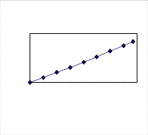
After plugging the module in the base unit the gain of PGA was adjusted manually to provide a fixed range of output 0-5V. This output was applied to V to I converter to provide a fixed range of current 4-20 mA. The same output was also applied to ADC whose digital output changes from 000H to FFFH. For the same module the simulated inputs were applied for all remaining types and ranges and every time the gain of PGA was adjusted manually to provide same 0-5V range of output. This procedure was repeated for all eight modules. The microcontroller software was then stored in the internal EEPROM of microcontroller 89C51. After testing complete instrument, when a particular module was plugged in the base unit it was observed that as the simulated input changes over a selected measurement range, the instrument provides all the outputs simultaneously. It was observed, as shown in Fig.5, that as the simulated input increases the output increases from 0-5 V.
Results and Discussion
Intelligent sensor interface is a rapidly expanding area of research, which will inevitably bring extraordinary changes in the current medical , industrial, avionics, consumer products, space research, manufacturing, and many other real life problems. Many scientists and engineers who are confronted with real life sensor problems agree that solution will only be found when an intelligent universal sensor interface, with standard outputs, can be produced. It. The UTI chips are available in the market and are costly and include high performance front-end circuits for resistive and capacitive sensors only
Output in Volts
Response of signal conditioning card for Pt 100
6
4
2
0
100 105 110 115 120 125 130 135 140
Resistance in Ohms
Fig. 4
Fig.4
Fig.5
For practical utility of any sensor it is important to tailor its performance according to the need of the application. The present system provides interface for commonly used 8 different sensors and four types of outputs, which are useful in both the scientific research and industrial processes interacting basically with control systems, process instrumentation, etc. Present paper particularly deals with the development of a versatile intelligent instrument that reduces the burden of the system designer. The user has to only set the position of DIP switches present on the sensor specific signal-conditioning module and then plug the module in the base unit. The microcontroller controls the overall operation of the instrument intelligently. Depending upon the need one can use the required outputs, which are provided. If user wants to use the sensor, whose interface is not provided in this system, then he has to only make a signal-conditioning card for that sensor. The present system is slow in acquiring number of samples per second as compared
to commercial available interfaces but using faster ADC and increasing the number of sensors connected to the system can improve performance. The GPIB interface can also be provided.