

Sharukh khan & Shahabaz Khan
![]()
![]()
T
HE main Aim of this project is to develop a system that can detect the alcohol content in the air exhaled by the driver and automatically turn off the car if Alcohol percentage exceeds the limit.
In this project I am using 8051 family micro controller. In this we are going to embed the program to receive data from alcohol sensor, convert it into digital form and then control the ignition system. Alcohol sensor gives out analog data that can’t be analyzed by 8051 so we use analog to digital converter to convert it in to digital format. After that the data is stored and then compared to threshold values if the value is beyond its limits then controller takes appropriate action. Here in this project we are going to turn OFF the ignition system, by doing so we can stop the car and prevent accidents that occur due to drink and drive. Here we can use Triacs or electro mechanical relays to control the ignition system.
Key words: Q3 sensor, 8051 micro controller, (230-12)V Step-down Transformer, 5v Dc motor
—————————— ——————————
![]()
INTRODUCTION
According to a survey done by W.H.O Almost every 90 seconds, a person is injured in a drunken driving crash. One in three people will be involved in an alcohol-related crash in their lifetime. In America on average, nearly 12,000 people die every year in DUI-related accidents. 900,000 are arrested each year for DUI/DWI and a full 1/3 of those are repeat offenders. Because of Drunk and Drive the people are highly injured or sometimes dead.
![]()
![]()
Sharukh khan, Under-Graduation Final year Student, Dept. of ECE, SIND-JNTUH,A. P,
India sharukhan472@gmail.com
![]()
Shahabaz Khan, Under-Graduation First Year student, Dept. of EEE, SIND-JNTUH, A.P,
India shahabaz 100@gmail.com ,
This is killing not only the driver but also the co- passengers travelling on the road at the same time.
n order to overcome this problem scientist’s proposed a project “High Sensitive Alcohol sensor with Auto car Ignition Disable Function”.
![]()
HARDWARE DESIGN:
Hardware of this system has mainly two parts they are Power supply unit and a micro controller unit and the block Diagram of the
System is as Follows.

![]()
Block Diagram of Project
![]()
POWER SUPPLY UNIT:
The main functionality of the Power supply unit is to convert the 230v of Ac current into 5v Dc. This process is sub-divided into 4 Steps Transformer, Rectifier, Regulator and Filter.

![]()
Fig I (a) Power Supply Unit
In the power supply unit before current reaches from AC source to the micro controller it has to undergo some series of steps like Transforming
of Current from AC to DC, Low Pass Filtering and Attenuation of Noise.
![]()
Transformer: the transformer which we have used in this project is (230-12) V Ac step down transformer. The main function of this Transformer is to convert the 230v of Ac current into 12V Ac. the operating voltage of Transformer is 1amp and the operating frequency is 12 MHz the interfacing of Transformer is explained below.
. 
Fig. ii (a).(230-12)V Step-Down Transformer.
Step down transformer is one whose secondary voltage is less than its primary voltage. It is designed to reduce the voltage from the primary winding to the secondary winding. This kind of transformer “steps down” the voltage applied to it. As a step- down unit, the transformer converts high-voltage, low-current power into low-voltage, high-current power. The larger-gauge wire used in the secondary winding is necessary due to the increase in current. The primary winding, which doesn’t have to conduct as much current, may be made of smaller
gauge wire.

Fig ii (b).step down transformer
It is possible to operate either of these transformer types backwards (powering the secondary winding with an AC source and letting the primary winding power a load) to perform the opposite function: a step-up can function as a step- down and visa-versa. In order to increase transformer efficiency and reduce heat we choose metal type of the windings. Copper windings are much more efficient than aluminum and many other winding metal choices, but it also costs more. Transformers with copper windings cost more to purchase initially, but save on electrical cost over time as the efficiency more than makes up for the initial cost.
![]()
Rectifier Bridge: the main Aim of the bridge rectifier is to convert Ac current to Dc. In our project rectifier is connected to the output of the Transformer. The output voltage of the Transformer was 12v initially and after the conversion of Ac to Dc it has reduced to half of its operating voltage that is 6v.

![]()
Fig. iii Full wave Rectifier
A Full Wave Rectifier is a circuit, which converts an Ac voltage into a pulsating dc voltage using both half cycles of the applied ac voltage. It uses two diodes of which one conducts during one half cycle while the other conducts during the other half cycle of the applied Ac voltage. During the positive half cycle of the input voltage, diode D1 becomes forward biased and D2 becomes reverse biased. Hence D1 conducts and D2 remains OFF. The load current flows through D1 and the voltage drop across RL will be equal to the input voltage.
![]()
Filter: digital filter is a system that performs mathematical operations on a sampled, discrete- time signal to reduce or enhance certain aspects of that signal. Its main functionality is it removes all the unwanted frequencies from the signal (Low pass Filter) the signal and reduces the operating Frequency to 50 Hz.

![]()
Fig IV (a) Low Pass Filter
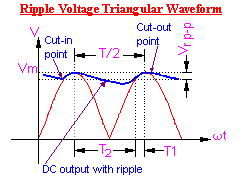
Working of LPF: A capacitor filter connected directly across the load is shown above. The property of a capacitor is that it allows ac component and blocks dc component. The operation of the capacitor filter is to short the ripple to ground but leave the dc to appear at output when it is connected across the pulsating dc voltage. During the positive half cycle, the capacitor charges up to the peak vale of the transformer secondary voltage, Vm and will try to maintain this value as the full wave input drops to zero. Capacitor will discharge through RL slowly until the transformer secondary voltage again increases to a value greater than the capacitor voltage. The diode conducts for a period, which depends on the capacitor voltage. The diode will conduct when the transformer secondary voltage becomes more than the diode voltage. This is called the cut in voltage. The diode stops conducting when the transformer voltage becomes less than the diode voltage. This is called cut out voltage. Referring to the figure below, with slight approximation the ripple voltage can be assumed as triangular. From the cut-in point to the cut-outpoint, whatever charge the capacitor acquires is equal to the charge the capacitor has lost during the period of non- conduction, i.e., from cut-out point to the next cut- in point.
![]()
![]()
Fig IV (b) Low pass Filter wave Form
![]()
(IV) Regulator: A voltage regulator is designed to automatically maintain a constant voltage level. Thus the voltage regulator regulates the voltage by 1V and constantly supplies the supply Voltage of 5V to the microcontroller at any instant of time.

![]()
Fig v Regulator Block Diagram and Working
![]()
Regulator Specification’s:
Vout range: 1.25 V – 37 V
Vin – Vout difference: 3 V – 40 V
Operation ambient temperature: 0℃ – 125℃
Output IMAX: less than 1.5 A (assuming factory-
suggested heat sinking)
Minimum Load Current max: 10 mA
The LM317 is a linear voltage regulator used in DC to DC converter applications. The overall function of
the LM317 is similar to that of the LM78xx series | Digital | data | viz, | machine | level | language. |
regulators. Whereas the 78xx series of regulators | ||||||
have fixed output voltages (ex. 7805 has 5V output), | ||||||
the LM317 can be adjusted to any voltage (within its limits). | ||||||
Linear regulators inherently draw as much current |
as they supply. When this current is multiplied by
the voltage difference between input and output, a significant amount of power is wasted as heat. This is not just inefficient, but a significant design consideration, a heat sink is commonly required. For large voltage differences, the wasted power can be more than the power supplied. This trade-off must be accepted when using linear regulators, which are a simple way to provide a stable voltage with few additional components. The alternative is to use a switching voltage regulator, which is usually more efficient, but tends to take up more space and require a higher component count (though there are exceptions).
MICRO CONTROLLER UNIT :
Micro Controller unit mainly comprises of 3Parts ADC Converter, 8051microcontroller and input/output devices and the brief explanation of the above mentioned topics are listed below with relevant examples and diagrams.
![]()
Analog to Digital Converter: We Know That System Understands Only Boolean Data and the Output of the regulator is Analog Value. That Is Why ADC Convertor Is Used .the main functionality of the ADC converter is to Covert the Analog Signal into
![]()
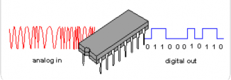
Fig VI. Analog to Digital Converter Operation
An analog-to-digital converter (abbreviated ADC, A/D or A to D) is a device that converts a continuous physical quantity (usually voltage) to a digital number that represents the quantity's amplitude.
The conversion involves quantization of the input, so it necessarily introduces a small amount of error. Instead of doing a single conversion, an ADC often performs the conversions ("samples" the input) periodically. The result is a sequence of digital values that have converted a continuous-time and continuous-amplitude analog signal to a discrete- time and discrete-amplitude digital signal.
An ADC may also provide an isolated measurement such as an electronic device that converts an input analog voltage or current to a digital number proportional to the magnitude of the voltage or current. However, some non-electronic or only partially electronic devices, such as rotary encoders, can also be considered ADCs. The digital output may use different coding schemes. Typically the digital output will be a two's complement binary number that is proportional to the input, but there are other possibilities. An encoder, for example, might output a Gray code.
The inverse operation is performed by a digital-to- analog converter (DAC).
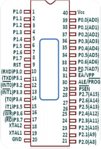
ii) 8051Microcontroller: A Microcontroller is an economical computer-on-a-chip built for dealing with specific tasks, such as displaying or receiving information through LEDs or remote controlled devices. In our project 8051 μ controller is used to compare the ADC output with the pre-defined reference voltage If it matches then μ controller will give command to the motor to work Accordingly let’s find out how...!
The Atmel versions of MCS51 supporting on-chip precision analog comparator are 89C2051 and 89C1051. The 8051 is designed as a strict Harvard architecture. The 8051 can only execute code fetched from program memory. The 8051 does not have any instruction to write to program memory. Most 8051 systems respect this distinction, and so are unable to download and directly execute new programs. The strict Harvard architecture has the advantage of making such systems immune to most forms of malware. Some 8051 systems have (or can be modified to have) some "dual-mapped" RAM, making them act somewhat more like Princeton architecture. This (partial) Princeton architecture has the advantage of making it possible for a Forth boot loader running on the 8051 to write new native code to RAM and then execute it, leading to faster incremental and interactive programming cycles than strict Harvard systems.
The MCS-51 has four distinct types of memory – internal RAM, special function registers, program memory, and external data memory.
Internal RAM (IRAM) is located from address 0 to address 0xFF. IRAM from 0x00 to 0x7F can be
accessed directly. IRAM from 0x80 to 0xFF must be accessed indirectly, using the @R0 or @R1 syntax, with the address to access loaded in R0 or R1. The
128 bits at IRAM locations 0x20–0x2F are bit- addressable.
Special function registers (SFR) are located in the same address space as IRAM, at addresses 0x80 to 0xFF, and are accessed directly using the same instructions as for the lower half of IRAM. They cannot be accessed indirectly via @R0 or @R1. 16 of the SFRs are also bit-addressable.
Program memory (PMEM, though less common in usage than IRAM and XRAM) is up to 64 KB of read- only memory, starting at address 0 in a separate address space. It may be on- or off-chip, depending on the particular model of chip being used. Program memory is read-only, though some variants of the 8051 use on-chip flash memory and provide a method of re-programming the memory in-system or in-application. In addition to code, it is possible to store read-only data in program memory, accessed by the MOVC A, @DPTR instruction. Data is fetched from the address specified in the 16-bit special function register DPTR.
External data memory (XRAM) is a third address space, also starting at address 0. It can also be on- or off-chip; what makes it "internal" is that it must be accessed using the MOVX (Move external) instruction. Many variants of the 8051 include the standard 256 bytes of IRAM plus a few KB of XRAM on the chip.
8
0
5
1
(µC)
There are various high-level programming language compilers for the 8051. Several C compilers are available for the 8051, most of which allow the programmer to specify where each variable should be stored in its six types of memory, and provide access to 8051 specific hardware features such as the multiple register banks and bit manipulation instructions. There are many commercial C compilers. SDCC is a popular [citation needed] open source C compiler. Other high level languages such as C++, Forth, BASIC, Pascal/Object Pascal, PL/M and Modula-2 are available for the 8051, but they are less widely used[citation needed] than C and assembly.
![]()
(iii) Input and output devices: The input and output devices are high sensitive Alcohol sensor & Dc motor. Alcohol sensor (MQ-3) is used to detect the Alcohol percentage and sends information to power supply unit. Dc motor is used as Engine it works in accordance with the output of Micro-controller.
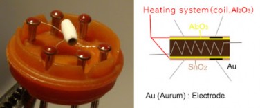
MQ3 SENSOR: This is an alcohol sensor from futurlec, named MQ-3, which detects ethanol in the air. It is one of the straightforward gas sensors so it works almost the same way with other gas sensors. It costs $6.90. Typically, it is used as part of the breathalyzers or breath testers for the detection of ethanol in the human
breath.
How does it work: The core system is the cube as you can see in this cross- sectional view, basically, it is an Alumina tube cover by SnO2, which is tin dioxide. And between them there is an Aurum electrode, the black one. And also you can see how the wires are connected. So, why do we need them? Basically, the alumina tube and the coils are the heating system, the yellow, brown parts and the coils in the picture.
Micro-controller Connections
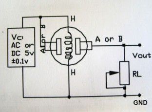
Here is the schematic. It is pretty simple. First, you can use 5v. And as you can see one of H pins goes to the power and the other one is connected to the ground. And the pin A is connected between the power and the pin H and the pin B is goes to the microcontroller. Also between the ground and the Arduino, you need the resistor. Before you connect
the resistor if you use the pot, you can tune the resistor for getting more accurate values. In the datasheet they say you can use 100 k_om to 470 k_om.
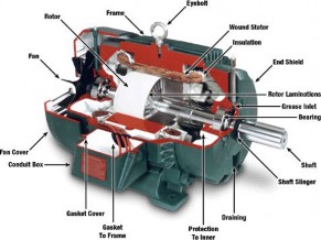
DC MOTOR: A DC motor is a mechanically commutated electric motor powered from direct current (DC). The stator is stationary in space by definition and therefore its current. The current in the rotor is switched by the commutator to also be stationary in space. This is how the relative angle between the stator and rotor magnetic flux is maintained near 90 degrees, which generates the maximum torque.
DC motors have a rotating armature winding (winding in which a voltage is induced) but non- rotating armature magnetic field and a static field winding (winding that produce the main magnetic flux) or permanent magnet. Different connections of the field and armature winding provide different inherent speed/torque regulation characteristics. The speed of a DC motor can be controlled by changing the voltage applied to the armature or by changing the field current. The introduction of variable resistance in the armature circuit or field circuit allowed speed control. Modern DC motors are often
controlled by power electronics systems called DC drives.
The introduction of DC motors to run machinery eliminated the need for local steam or internal combustion engines, and line shaft drive systems. DC motors can operate directly from rechargeable batteries, providing the motive power for the first electric vehicles. Today DC motors are still found in applications as small as toys and disk drives, or in large sizes to operate steel rolling mills and paper machines.
![]()
2. SOFTWARE
The software design involves mainly two parts programing part
And dumping part
![]()
(A)Programing Part: For Programing Part we use Software KEIL micro vision V4.0 and the program is as follows
#include<reg51.h>
#include<intrins.h>
//#define lcd_port p1
#include"lcd_busy.h"
#include"adc.h" sbit traic1=p2^7;
//sbit dc12=p0^1; Void main ()
{
lcd_init(); lcd_init(); lcd_init();
message(0x80,"atmtic gas lekge"); message(0xc0," detection "); delay(1000);
init(0x01); while(1)
{
//message(0x80,"temperature"); adcdata();
if(z<3000)
{
traic1=1;
//dc12=0;
essage(0x80,"no gas detected ");
}
if(z>=3000)
{
traic1=0;
// dc12=1;
message (0x80," gas detected ");
(B)Dumping Part: now let’s keep this as the values of flash magic in that please select
Select device: 89LV51RD32 COM port: COM24
Baud Rate: 9600 Interface: NONE (ISP)
Then say start and the program will be dumped
successfully into the micro controller then test the instruments.
![]()
4. CONCLUSION
Tests found that this system is highly effective and it’s efficient in testing the alcohol percentage of the human beings and if it crossed the threshold value the dc motor will stop working. It’s practically implemented in some cars ex: Nissan N90. This just not take at the time of igniting the car but also after few minutes because there is a chance of taking Alcohol at the time of driving so this project is highly useful for the safe and secure drive.
REFERENCES
Single walls carbon Nano tube networks for ethanol vapor sensing applications-ilya v. Anoshkin
CHEMICAL SENSORS. VOLUME 6: CHEMICAL SENSORS APPLICATIONS
The 8051 microcontroller-keynath j ayala
4.8051MicrocontrollerInternals, Instructions, Programming and Interfacing by Subrata Ghoshal
} 5. The 8051 Microcontroller and Embedded Systems
} using Assembly and C -by Mohammad Ali Mazidi
}
After the completion of this program translate, build then rebuild after that convert it into .hex file