Poission’s
ratio ( µ) 0.16 0.28 0.26
Modulus of
Elasticity
( E) N/mm2 0.223 x 10⁵ 0.21 x 10⁵ 0.723 x 10⁵
International Journal of Scientific & Engineering Research, Volume 3, Issue 11, November-2012
ISSN 2229-5518
Experimental Investigation on Reinforced Concrete Filled Steel Rectangular Fluted Columns
Eramma.H, B.R Niranjan
Abstract— Behaviour of Concrete Filled Reinforced Steel Tubular Columns having rectangular Flutes have been investigated by conducting experiment on thirteen Columns having 2.5m length and different L/D ratios. Columns reinforced and filled with SCC were tested wi th three different L/D ratios of 15, 20 and 25 and varying the longitudinal reinforcements with 3,4,5 and 6 number of reinforcement s. The columns were tested having its ends firmly held in position and analysed for its stiffness and strength. Though the columns were tested with L/D ratio of 25 , columns did not buckle, failing at the ends showing failure is by local buckling. The results are compared with the existing empirical equations and have found that the secant equation compares comparatively well with 50 to 60 per cent. Increase in longitudinal reinforcement in the columns have shown a maximum of 32 % of increase in axial load in the case of Columns with L/D ratio of 25 with 4 number of bars.
Keywords: CFSFC, CFST, SCC, Composite, Circular Column, Rectangular Flutes.
—————————— ——————————
FST (Concrete Filled Steel Tubes) Columns came into ex- istence during early 1960. Substantial research has been made to understand the behaviour since then (1-21).The advantage of using these CFST Columns have been found by Japanese first and employed in the construction of multi- storeyed buildings effectively. Now, the analysis and Design of these CFST Columns have found place even in Codes and Specifications. It has been envisaged to study strength, stiff- ness and buckling characteristics by providing flutes to steel sheet of columns which enhances aesthesis of columns. Also, fluted columns enhances the strength and also stiffness as the surface area of steel sheet and moment of inertia of the column increases. The advantage of steel members having high tensile strength and ductility and concrete members having better compressive strength have been better made use as a compo- site member. Additional longitudinal reinforcement in the columns makes the columns still stronger. Hence, it has been envisaged to check whether such a columns would act as a
slender.
Research has been in progress around the world on exper-
imental and analytical studies on Concrete Filled Steel Tubular
Columns for more than four decades. Substantial contribution
has been made since then in understanding the behaviour of
CFST columns and to arrive at a design procedure. Quite few
countries have incorporated the design procedure in their re-
spective codes also.
Most of the researchers (1-21) have considered the contri- bution of geometric properties like shape, L/D ratio, t/D ratio,
————————————————
Dr. B.R.Niranjan Professor, University Vishvesvaraiah College of Engi- neering, JB Campus, BU, Bangalore-560056, Karnataka, India. E-mail:
br_niranjan@yahoo.co.in
boundary conditions, strength of materials and the loading conditions. It has been found that generally the failure occurs by either local buckling or yield failure. It has been found that Euro code gives a better design method which yields values nearer to experimental values.
Studies performed on different L/D ratios with small ec- centricities have yielded that the degree of confinement of- fered by a thin walled circular steel tube to the internal con- crete is dependent on the load conditions.
Mild steel sheet having thickness 0.8 mm has been pressed in a mill to obtain five rectangular fluting of 40 mm width 10 mm at apex uniformly along the length. These sheets were given a tubular shape and tacked along the edges at an interval of 250 mm along the length of the column. The number and the size of the flutes remained same irrespective of the diameter of the column i.e., for different L/D ratios. The development length of the width of each of these columns with different L/D rati- os as compared to a circular column of the same diameter is
24, 29 and 34 % for L/D ratios of 15, 20 and 25 respectively. Reinforcement cage is then placed inside these fluted tubes taking care to maintain the necessary cover. The five types of columns have been shown in Fig 2.1(a) & Fig 2.1(b).Though regular ties have not been used, however four ties have been provided at equal distances to keep the reinforcement in posi- tion. A Self Compacting Concrete of design mix M20 designed as per Nan Su method(22) and tested for conformity as per IS specifications is poured into the fluted steel tube. These col- umns were cured for 28 days by frequently pouring water over top of the column. Pilot specimens cured in a similar manner were tested to know the basic properties and are en- tered in Table 1.
IJSER © 2012
The research paper published by IJSER journal is about Experimental Investigation on Reinforced Concrete Filled Steel Rectangular Fluted Columns
ISSN 2229-5518
TABLE 1.
Details of testing of the materials from experimental results
each end of the specimen. The columns were at placed restraining rotation at both ends. Care was taken to ensure that truly axial load
was transformed to each of the columns. This was achieved by using
Materials Concrete Reinforcement Steel Sheet![]()
Poission’s
ratio ( µ) 0.16 0.28 0.26
Modulus of
Elasticity
( E) N/mm2 0.223 x 10⁵ 0.21 x 10⁵ 0.723 x 10⁵
Remarks | Split tensile | Tensile test | Tension |
strength test | coupon test |
![]()

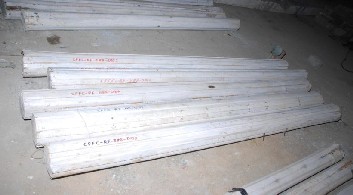
Fig 2.1.(a) Fluted steel tube without reinforcement

Fig 2.1.(b) Fluted steel tube with reinforcement
The tests were conducted using a 2000 kN capacity hydraulic jack placing the specimen in the testing machine as shown in Fig.2.2. The bearing surfaces of the testing machine and the bearing plates were wiped clean and any loose sand or other material removed from the surface of the specimen. Which were to be in contact with the bear- ing plates. The specimen was placed between the bearing plates in such a manner that the upper bearing plate was directly in line with the lower plate and the bearing plates extend at least 25 mm from
plumb bob and Theodolite.
Fig. 2.2. Experimental Set Up.

Fig 2.3. Connection of Dial Test Indicators Laterally
Foil strain gauge (8mm x 8mm) 350 + 0.5 Ω has been used to measure the strains at the center of the steel tube and center of the reinforcement (core) of the specimens. Three numbers 50 mm dial test indicator with a least count of 0.01 mm one for axial and the other two for lateral were used to measure axial and lateral deformations upon loading as shown in Fig 2.3. Apart from these instruments plumb bob and linear scales have been used.
Behaviour of the columns has been studied with respect to defor- mation characteristics in the axial direction and in the transverse direction. Strains have been measured on the steel sheet in two per- pendicular directions.
IJSER © 2012
The research paper published by IJSER journal is about Experimental Investigation on Reinforced Concrete Filled Steel Rectangular Fluted Columns
ISSN 2229-5518

Generally the columns have shown linear behaviour up to about one third of the total load that is about 200 kN axial compressive load. It was envisaged to study the buckling characteristic because of the less width to length of column. None of the columns have shown buckling, near the mid portion of the column. The confinement of the column is so large and even the columns without the longitudinal reinforcement have not shown any buckling. All the columns have failed near supports of column showing local buckling .Columns with L/D ratio of 25 also have not buckled. Behaviour of each col- umn and its characteristics have been explained in subsequent arti- cles. Among various number of reinforcements, the ultimate load has been found to be maximum for L/D ratio of 15, 20 and 25 to be in 4 number of reinforcements as shown in Fig.3.

Fig 3 Ultimate load v/s Area of reinforcement
Fig 3.1 (a) Load Vs Strain
Columns without reinforcement have been tested with L/D ratios of
15, 20 and 25 to compare with the columns having reinforcement. For columns with L/D ratio of 15 and 20 the yield load with 500 kN
& 400 kN where as for the other column with L/D ratio of 25, the yield load got reduced by 70 & 63 % . As the L/D ratio increased the maximum load has reduced by 18 and 43 % as compared to the column with L/D ratio of 15, showing that the column strength re- duces to three fourths and to half as the L/D ratio is reduced from 15 to 20 and 25 respectively. The lateral deformation has increased by
54% and 42% as L/D ratio increased from 15 to 20 and 25 respec- tively. The maximum strains recorded were 414, 55 and 129 mi- crostrains along the axial direction on the steel sheet. The variation of strains for various loads is depicted in Fig 3.1 (a). Similar read- ings were observed in the other dial gauge kept perpendicular. The load Vs axial deformation and lateral deformation is shown in Fig
3.1.(b) and 3.1(c). The stress Vs strain is shown in Fig 3.1 (d). The column failed due to local buckling, the failure being at the bottom of the column at a distance of 230 mm , 360 mm and 180 mm at top for L/D ratio of 15,20 and 25 respectively. The sheets have opened up at the bottom of the column for L/D ratio of 15 and the sheets have opened up at the top of the column for L/D ratios of 20 and 25 respectively.
Fig 3.1 (b) Load Vs Axial deformation

Fig 3.1 (c) Load Vs Lateral deformation
IJSER © 2012
The research paper published by IJSER journal is about Experimental Investigation on Reinforced Concrete Filled Steel Rectangular Fluted Columns

ISSN 2229-5518

Fig 3.1 (d) Stress Vs strain
Fig 3.1 Behaviour of columns CFSFC-NR
Testing of columns having reinforcements of three number of 8 mm rods with three different L/D ratios have been reported here. Both yield loads and the maximum loads have reduced as the L/D ratio increased. The yield load was 450 kN for the column with L/D ratio of 15 and reduces to 22 % and 56% for L/D ratio of 20 and 25. The maximum load is 550 kN for L/D ratio of 15 and reduces to 0 % and 22 % for L/D ratios of 20 and 25 showing that the strength re- duces to almost quarter as the L/D ratios reduces from 15 to 25. The distance at which the failure occurred by opening up of sheet is at a distance of 330 mm at bottom , 250 mm from bottom and 230 mm from top for L/D ratios of 15 , 20 and 25 respectively, showing that the failure can either be at top or bottom of the column. Strains have almost remained same as the L/D ratio increases as shown in Fig
3.2(a). The maximum deflection decreases as the L/D ratio increases as can be seen in Fig 3.2 (b). Load Vs maximum lateral deformation has been shown in Fig 3.2 (c). Which shows that though, not much
of deformation exists , slight lateral deformation has been observed for the column with L/D ratio of 25. The maximum lateral defor- mation has been observed to be 3.04, 8.38 and 2.02 mm respec- tively. For L/D ratio of 15, 20 and 25. It can also be observed that the strains are more in the reinforcement and not on the steel sheet. The stress Vs strain is shown in Fig 3.2 (d).
Fig 3.2 (a) Load Vs Strain
Fig 3.2 (b) Load Vs Axial deformation

Fig 3.2 (c) Load Vs Lateral deformation

Fig 3.2 (d) Stress Vs strain
Fig 3.2 Behaviour of columns CFSFC -3/#8
For the dimension of column chosen four number of reinforcements
appears to be optimum as the yield .and ultimate load is maximum for the parameter that have been chosen. The maximum load resist- ed by the column with L/D ratio of 15 is 800 kN. It has been ob- served that as the L/D ratio reduces from 15, ultimate load reduces to
23 % and 38 % for L/D ratio of 20 and 25 respectively. The max- imum strains recorded were 527,632 and 337 microstrains along the axial direction on the steel sheet. The variation of strains for various loads is depicted in Fig 3.1 (a). The maximum deflection both in longitudinal direction and lateral direction have been ob-
IJSER © 2012
The research paper published by IJSER journal is about Experimental Investigation on Reinforced Concrete Filled Steel Rectangular Fluted Columns
ISSN 2229-5518

served to be 14.8, 26.88 & 26 and 6.94, 4.06 and 4.67 respectively for the column with L/D ratio of 15, 20 and 25. The graph of load Vs deformation have been shown in Fig 3.3 (b) and (c). As has been in earlier cases, little more horizontal deformation has been ob- served for columns with L/D ratio of 25. The stress Vs strain is shown in Fig 3.3 (d). The distances at which the failure occurred are
280 mm from bottom 210 mm from top and 260 mm from bottom support showing that the fracture location gets nearer to the bottom as L/D ratio reduces.
Fig 3.3 (d) Stress Vs strain
Fig 3.3Behaviour of columns CFSFC-4/#8

Fig 3.3 (a) Load Vs Strain

Fig 3.3 (b) Load Vs Axial deformation

Fig 3.3 (c) Load Vs Lateral deformation
For the columns with 5 bars, L/D ratio considered are 15 and 20 only as the five numbers of reinforcement could not be placed in the col- umn with an L/D ratio of 25 i.e., with the column diameter of 100 mm. Hence only two columns have been tested in this category along with the column having no reinforcement. Columns with L/D ratios of 15 and 20 has resisted similar loads as that of column with four number of bars. The yield load is 10 % and 40 % less as compared to non reinforced column.
As can be seen from Fig.3.4 (a), Load Vs Strain, the strain has increased constantly up to a load earlier to yield load and later has remained constant where as for L/D 20, the strain has increased up to about 300kN i.e yield load and later it has drastically changed. The axial deformation is about 27% more and 1 % less as compared to the column with same L/ D ratio without reinforcement as shown in Fig 3.4 (b). Fig. 3.4(c) depicts behaviour of load vs. lateral defor- mation, the lateral deformation remained almost same as compared to that of column without reinforcement, showing stiffness re- mained same even with reinforcement of 5 longitudinal bars in the column. The stress Vs strain is shown in Fig 3.4 (d).
Fig 3.4 (a) Load Vs Strain
IJSER © 2012
The research paper published by IJSER journal is about Experimental Investigation on Reinforced Concrete Filled Steel Rectangular Fluted Columns
ISSN 2229-5518

failure occurred at top and bottom for L/D ratio 15 and 20 respec- tively at a distance of 330 mm and 300 mm. The maximum strains recorded were 478 and 269 microstrains along the axial direction on the reinforcement. The variation of strains for various loads is depicted in Fig 3.1(a). The axial deformation is about 62% more and
8 % less as compared to the column with same L/ D ratio without reinforcement as shown in Fig 3.4(b). Fig 3.4(c) depicts behaviour of load vs. lateral deformation, the lateral deformation by 44% more as compared to that of column without reinforcement for L/D ratio
15 and20 respectively, showing stiffness remained same even with reinforcement of 5 longitudinal bars in the column. The stress Vs strain is shown in Fig 3.5 (d).
Fig 3.4 (b) Load Vs Axial deformation 
3.5 (a) Load Vs Strain
Fig 3.4 (c) Load Vs Lateral deformation 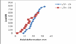
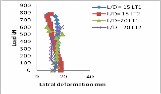
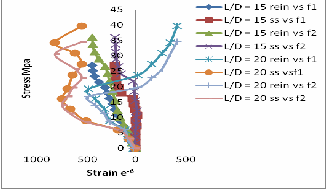 Fig 3.5 (b) Load Vs Axial deformation
Fig 3.4 (d) Stress Vs strain
Fig 3.4 Behaviour of columns CFSFC-5/#8
As has been indicated earlier, because of the constraint of placing bars L/D ratio of 15 and 20 have been considered here. Both the
yield loads for L/D 15 and 20 have increased by 10 % and de- creased by 38 % where as the ultimate load increased by 16% and
9% compared to that of no reinforcement column. When compared to columns with 5 bars in columns,, the yield load has increased by about 22% and 0% for L/D ratio of 15 and 20 and ultimate load increased by 4% and 15%. The maximum load reduces by about 10
% when the column dimension increased from L/D 15 to 20. The
IJSER © 2012
Fig 3.5 (c) Load Vs Lateral deformation
The research paper published by IJSER journal is about Experimental Investigation on Reinforced Concrete Filled Steel Rectangular Fluted Columns

ISSN 2229-5518
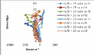
Fig 3.5 (d) Stress Vs strain
Fig 3.5 Behaviour of columns CFSFC-6/#8

4(a). Failure of all columns ( buckling does not exist)
4 (b). Failure of columns at edges for L/D 15
4(c). Failure of column L/D 25 at top with 3/#8

4(d) Failure of column CFSFC L/D 20 at bottom with 3/#8
Fig 4. Failure of columns
These results of tests of CFSFC have been compared with the results of various existing theoretical equations given here under.
4.1 Euler’s equations
Pcr= ( π^2 EI)/l^2 = fc A
4.2 Rankine-Gorden’s formula
P = (f_c× A)/((1+α(l/k )^2))
4.3 Secant formula
P = ( f ×A)/({1+e (y_c/k^2 ) }× { 1 + α (l^2/k^2 ) } )
4. 4 Tangent Modulus equation
(P/A)cr = (π^2 E_t)/(l/k)^2 = fc x A
4.5 Rankine-Merchant’s formula
fac = {0.66 {f_cc x f_y }/[〖f_cc〗^n + 〖f_y 〗^n ]^((1/n) ) }
4.6 Infilled columns
Pa =1.1 A_c f_cc [ 1-((0.000025 L^2)/〖r_c〗^2 ) ]+
A_s f_sc + Ast fst
4.7 IS: 456-2000
Pu = 0.4 fck Ac + 0.67 fy Asc
Composite section
Pu = 0.4 fck Ac + 0.67 fy Asc + 0.67 fss Asc
IJSER © 2012
The research paper published by IJSER journal is about Experimental Investigation on Reinforced Concrete Filled Steel Rectangular Fluted Columns
ISSN 2229-5518
Reduction factor Cr has not been considered as none of the columns have shown any sort of buckling.
4.8 Nominal Design
p = p1 + p2 + p3
Where p1 = L x t x fy (Load taken by steel sheet)
p2 = Ac x fck = [(π(d)^2 /4) + 5 ( l x h) ] x fck
( Load taken by concrete)
p3 = Ast x fy = [(π(d)^2 /4) x n] x fy
( Load taken by reinforcement)
These equations have been modified to consider equivalent area, moment of inertia and young's modulus of that of CFSFC members . The values obtained from these equations have been compared with the experimental values and are tabulat- ed in table 2. It can be observed that the values obtained by tangent equation are about 40% conservative as compared to that of no reinforcement column for the column with L/D ratio of 15, 20 and 25.
The reinforcement improves the axial strength of the column by about 19% , 13 % and 32 % for 4 number of reinforcements with L/D ratio of 15, 20 and 25 as compared to the column with no reinforcement.
The strength of Column reduces by 25% and 50%
when L/D ratio reduces from 15 to 20 and 15 to 25.
All the columns have failed near the supports of the
column.
As the reinforcement in the column increased the dis- tance of failure point moves towards centre of the
column and as L/D reduces the failure point moves towards the support.
As number of reinforcement increases the distance of failure due to buckling has also increased by 43%,
22%, 65% & 43% respectively. For 3,4,5 & 6 number of reinforcements for L/D = 15. Similar results have also been found for other L/D ratios.
No buckling has been observed for any of the col- umns even with higher L/D ratio of 25
The lateral deformation is more in the case of 4 num- ber of reinforcement with L/D ratio of 25.
The authors wish to thank the authorities of Bangalore Uni- versity for giving an opportunity to conduct the experiments in the Structural Engineering Laboratory of Faculty of Engi- neering-Civil.
[1] Artiomas Kuranovas, Audronis Kazimieras Kvedaras 2007, “Behavior of hollow concrete-filled steel tubular composite elements”, Journal of Civil En- gineering and Management 2007, Vol XIII, No 2, 131–141
[2] Bridge, RQ & O’Shea, MD,1997, “Local buckling of thin–walled circular steel sections with or without internal restraint” Journal of Constructional Steel Re- search, vol. 41, No.2/3, pp. 137-157.PII:S0143-974X(97)00002-3
[3] Bridge, RQ & O’Shea, MD, 1998, “Behavior of thin-walled steel box sections with or without internal restraint”, Journal of Constructional Steel Research , vol. 47, pp. 73-91.
[4] Bridge, RQ & O’Shea, MD, 2000, “Design of circular thin-walled concrete
filled steel tubes “Journal of Structural Engineering, ASCE, Proc. 126, 1295-
1303.
[5] Brian Uy, 2001, “Local and post-local buckling of fabricated steel and compo- site cross sections”, Journal of Structural Engineering, ASCE, vol. 127, no. 6, pp.666-677.
[6] Bradford, MA, Loh, HY & Uy, B, 2002, “Slenderness limits for circular steel tubes”, Journal of Constructional Steel Research, vol. 58, pp. 243-252.
[7] Brian Uy et al, 2003, “Strength of Concrete Filled Steel Box Columns Incorpo- rating Interaction Buckling”, Journal of Structural Engineering,ASCE, vol 129 pp. 626-639.
[8] Dung M. Lue, Jui-Ling Liu, Tsong Yen 2007, “Experimental study on rectan- gular CFT columns with high-strength concrete”, Journal of Constructional Steel Research, 63 (2007) 37–44.
[9] Giakoumelis. G & Lam. D, 2004, “Axial capacity of circular concrete-filled
tube columns”, Journal of Constructional Steel Research, vol. 60, pp. 1049-1068 [10] Ferhun C. Caner; and Zdenek P. Bazant, F., 2002, “Lateral Confinement Needed to Suppress Softening of Concrete in Compression Journal of Engi-
neering Mechanics, December 2002 pp 1304-1313.
[11] Fam, A, Qie, FS & Rizkalla, S, 2004, “Concrete-filled steel tubes subjected to axial compression and lateral cyclic loads”, Journal of Structural Engineering, ASCE, vol. 130, no. 4, pp. 631-640.
[12] Huang C. S. et al 2002, “Axial Load Behavior of Stiffened Concrete-Filled
Steel Columns”, Journal of Structural Engineering September 1222-1230.
[13] Hu, HT, Huang, CS, Wu, MH & Wu, YM, 2003, “Nonlinear Analysis of Axial- ly Loaded Concrete-Filled Tube Columns with Confinement Effect”, Journal of Structural Engineering, ASCE, vol. 129, no. 10 pp. 1322-1329.
[14] Johansson, M & Gylitoft, K,2002, ‘Mechanical behavior of circular steel com- posite stub columns’, Journal of Structural Engineering, ASCE, vol.128, no.8,pp.1073-81.
[15] Kefeng Tan, John M. Nichols and Xincheng Pu 2003, “Mechanical Properties
of High Strength Concrete Filled Steel Tubular Columns: Part 1 - Concentri- cally Loaded”, ACI Journal April 2003.
[16] Liang QQ, Uy B & Liew JYR, 2006, “Nonlinear analysis of concrete-filled thin- walled steel box columns with local buckling effects”, Journal of Construc- tional Steel Research, vol. 62, pp. 581-591.
[17] Min – Lang Lin and Keh- chyuan Tsai, “ Mechanical behavior of double- skinned composite steel tubular columns “, National Center for Research on Earthquake Engineering, Taipei, Taiwan.
[18] Shosuke Morino, Keigo Tsuda, “Design and construction of concrete-filled steel tube column system in Japan”, Earthquake Engineering and Engineering Seismology, Vol. 4, No. 1 pp 51-73.
[19] X.X Zha & Sumei Zhang 2003, “Comparison with current codes in the world for Concrete Filled Steel Tubular structures” Harbin Institute of Technology, China.
[20] Zeghichea .J, K. Chaoui, 2005, “An experimental behavior of concrete-filled
steel tubular columns”, Journal of Constructional Steel Research 61 (2005) 53–
66.
[21] Zhi-wu Yu, Fa-xing Ding, 2007, “Experimental behavior of circular concrete- filled steel tube Nan Su, Kung-Chung Hsu, His-Wen Chai “ A simple mix design method for self stub columns”, Journal of Constructional Steel Re- search 63 (2007) pp. 165–174
[22] Nan Su, Kung-Chung Hsu, His-Wen Chai “ A simple mix design method for
self – compacting concrete” Cement and Concrete Research 31 (2001) 1799 –
1807.
IJSER © 2012
The research paper published by IJSER journal is about Experimental Investigation on Reinforced Concrete Filled Steel Rectangular Fluted Columns
ISSN 2229-5518
BIBLOGRAPHY
[1] Dayaratnam.P, Limit state design of reinforced concrete structures, 2004 [2] Sinha S.N, Reinforced Concrete Design, First Revised Edition, Tata
McGraw Hill publishing company limited.
[3] CHU-KIA WANG & CHARLESS G. SALMON, Reinforced Concrete
Design, Sixth Edition , International Text book company.
[4] Krishna Raju .N, Advanced reinforced concrete design, CBS Publica- tions.
[5] Dr.Prakash Rao D.S, Strength of materials, A practical approach Vol- ume1, University press (India) Limited Publications.
[6] Ashok. K. Jain , Reinforced Concrete Limit State Design , Third Edition
1989. Published by Nem Chand & Bros, Civil lines Roorkee INDIA.
[7] Shetty , M.S., “Concrete Technology” Theory and Practice., First Multi- colour Illustrative Revised Edition 2006.
[8] Krishna Raju . N ; “Design of Concrete Mixes” , Third Edition, 1988, CBS Publishers & Distributors.
[9] Neville, A.M ; “Properties of Concrete”, Fourth Edition 2006, Published
by Dorling Kindersley (India) Pvt, Ltd.
[10] Gambhir, M.L ; “Concrete Technology “Third Edition 2006, Published
by Tata McGraw-Hill Publishing Company Limited.
[11] Neville, A.M & J.J Brooks ; “Concrete Technology” First Edition 2006, ,
Published by Dorling Kindersley (India) Pvt, Ltd.
[12] Santhakumar, A.R; “Concrete Technology”, Oxford Hihger Education
2007, Published in India by Oxford University Press.
IJSER © 2012
The research paper published by IJSER journal is about Experimental Investigation on Reinforced Concrete Filled Steel Rectangular Fluted Columns
ISSN 2229-5518
TABLE 2.
Details Of Load Carrying Capacities Of CFSFC From Experimental And Empirical Val- ues.
IJSER © 2012