International Journal of Scientific & Engineering Research, Volume 5, Issue 4, April-2014 809
ISSN 2229-5518
Experimental Investigation For Flow Through combined trapezoidal Weir and rectangular gate
![]()
Saleh I. Khassaf. and Maha Habeeb
![]()
Abstract: This study based on laboratory experiments to investigate the characteristics of the combined flow over a sharp crested trapezoidal weirs and below a rectangular slues gate considering the study of the effects of the upstream flow depth, the depth of flow over the weir, and trapezoidal weir angle on the discharge coefficient Cd. Dimensional analysis techniques and (STATISTICA) program were used for finding new empirical formula with help of the experimental data.
Keyword: flow, weir , gate, hydraulic models .
![]()
1- Introduction
Water control structures are used to manage the hydrological regime by modifying the direction or rate of flow of water, and / or to maintain a desired water surface elevation. It can be designed to provide solutions to suit a range of natural resource management issues, but in the same time these control structures may be caused a real problem in the natural waterway systems one of those major problem are sediment and deposit
Weir and gate are two of the oldest, common and important structures used to control and measure the flow of water in open channels . The weir pool should be cleaned of sediment as it accumulates to maintain accurate flow measurement . A sluice gate is a bottom opening in a wall, commonly used in control of rivers and channel flows. One disadvantage of the sluice gates is they retained the floating materials . In order to minimize their disadvantages and to maximize their advantages, weirs and gates may be combined together in one device yielding a simultaneous flow over the weir and below the gate. The combined weir and gate systems can be used in minimizing sedimentations and depositions.
Alhamid,Negm and Al-Brahim (1997), Fadil (1997) developed a meter for the combined flow through contracted sluice gate and weir, also combined-submerged flow through weirs and below gates were analyzed and discussed by Negm et al.(1999),Negm(2000).The characteristics of the combined flow over weirs and below gates of equal contraction are discussed by Abdel-Azim et al.(2002), different geometrical combination are used, the discharge characteristics of a combined weirs and gate structure are discussed, they found that the flow parameter (H/d) (the ratio between the upstream water depth and the height of the gate opening) and the geometrical parameter (y/d) (the ratio of the vertical distance between the lower edge of the weir and the upper edge of the gate opening and the height of the gate opening) have major effects on the discharge. In the present work the characteristics of the combined flow over a trapezoidal weir with different angles and below a rectangular gate are studied.
2- - Theoretical Bakground
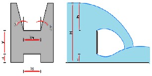
(Fig.1) shows a definition sketch for the free flow over a contracted sharp-crested trapezoidal weir combined with contracted sharp crested rectangular gate.
(a) (b)
Fig.(1): definition sketch for combined free flow over weir and under gate.(a) cross section.(b) longitudinal section
to compute the discharge through a combined device For free flow conditions. the following equation may be obtained by adding the discharge over the weir to the discharge below the gate as:
Q = Qw + Qg (1)
Where: Q=total flow rate, Qw=discharge over the weir,Qg=discharge
through the gate. see (chow,1973) as shown in fig(2)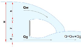
Fig.(2):total flow equal the sum of flows above and below the structure
IJSER © 2014 http://www.ijser.org
International Journal of Scientific & Engineering Research, Volume 5, Issue 4, April-2014 - 810 - ISSN 2229-5518
Based on eq.(1) and using dimensional analysis, the dimensional relationship can be obtains:![]()
𝑸𝒂𝒄𝒕.
�𝒈 𝒅𝟐.𝟓
![]()
𝑯
= 𝒇 �
𝒅
![]()
![]()
𝒉 𝒚
, ,
𝒅 𝒅
![]()
𝒃𝒈
,
𝒅
![]()
𝒃𝒈
,
𝑩
![]()
Ө
, 𝐭𝐚𝐧
𝟐
, 𝐑𝐞, 𝐖𝐞� (𝟐)
Where H= total head , h= head of water over weir, d= the gate height, y= vertical distance between the lower edge of the weir and the upper edge of the gate opening, bw=weir crest length, bg=gate width,
B=channel width, Ө=trapezoidal angle, Re= Reynolds number, We=
Weber number. And because (Re and We can be represented by one
dimensional variable h or H)Ackers,1978.The functional relationship eq. (2) can be written In terms of Cd as:![]()
𝑪𝒅 = 𝒇 𝑯
𝒅
3-Experimental work.
![]()
, 𝒉
𝒅
![]()
, 𝒚
𝒅
, 𝒕𝒂𝒏
![]()
Ө
� (3)
𝟐
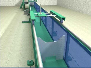
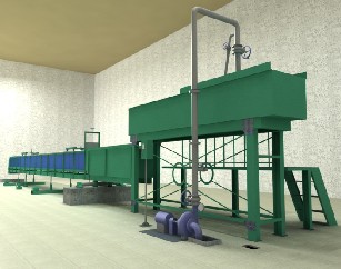
Fig.(4): working section, point gauge, and the model.
The experiments were carried out in a rectangular channel of 18.6m length with cross-section 0.5m wide and 0.5m high. The walls of the channel were a toughened glass with number of perpex panels incorporated. The bed of the channel consisted of stainless –steel plates.Twenty five models were tested , they were made of 3 mm thick Plexiglas sheet with all the edges were beveled at 45º to form sharp edges of about 2 mm thickness. The models were fixed to the flume at the middle using a supports from downstream sides having the same shape with a large dimension was made from a Plexiglas sheet 10 mm thick stuck to the flume side walls using silicon rubber .Water depth were measured with point gauges(±0.1 mm accuracy).
The actual discharge obtained by measured the water level in a well box located at a distance four times the head over the v- notch weir crest particular for this purpose consist of hook gage installed in The above and one of its sides of the transparent glass to facilitate the process of reading the height of the water over weir crest .
Table (1) gives the range of various parameters covered in the present study. W hile the other geometric parameter are kept constant
(d=7, bw=20, bg=20) cm.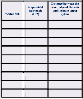
Table(1): The tested models dimensions .
1 14 5
2 14 10
3 14 15
4 30 5
5 30 10
6 30 15
Fig.(3): the flume
7
45 5
8
45 10
9
45 15
IJSER © 2014 http://www.ijser.org
International Journal of Scientific & Engineering Research, Volume 5, Issue 4, April-2014 - 811 - ISSN 2229-5518
gage installed in The above and one of its sides of the transparent
All models tested for seven different discharges lays in the range of![]()
𝑯
𝑪𝒅 = 𝑶. 𝟓𝟐𝟔 ∗ � �
𝒅
𝟎.𝟎𝟖𝟑
![]()
𝒉
∗ � �
𝒅
𝟎.𝟎𝟑𝟒
![]()
𝒚
∗ � �
𝒅
−𝟎.𝟎𝟏𝟑
minimum to maximum discharges equal to (19.8-40.5) l/sec. respectively.
4-Results and discussion
(4)
∗ �𝒕𝒂𝒏
![]()
𝜽 𝑪𝟎.𝟎𝟑
�
𝟐
variation of Cd with (y/d):
The distance below the weir edge and the rectangular gate (y) have significant influence on discharge coefficient value in combined device. Fortunately, the effect of this parameter would be significant when the effectiveness of other parameter is absent.For that reason, nine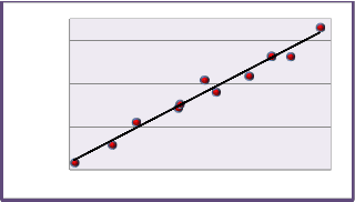
Another data is used to testing the equations, a statistical comparison of equation is used to show the convergence of the predicted to the observed records , the value of R^2 are given good agreement for all data as shown in Figure (7).
models were tested by sixty three runs represents models NO.(1-9).
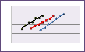
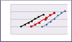
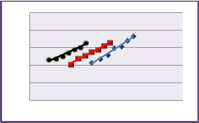
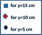
Figures(5a,5b,and5c)shown typical variation of Cd with H/d for three different y (=5,10,15) cm are displayed. three different angles of the
trapezoidal weir in combined device , �ɵ/2 =14°, 30° and 45°).From
these figures, one can conclude that the data grouped into different
categories according to y/d. Thus the effect of the parameter y/d control the variation of Cd with H/d. and For a particular H/d, Cd increase as y/d increase,
This can be explained as follows:(In the case of both the weir and the
0.59
0.58
0.57
0.56
sluice gate, the discharge is directly dependent upon the headwater level. However, while in the case of a weir the discharge increases exponentially with increasing height of the water level above the weir sill' )(Gangolf-1989). S0 for constant (d) and variable (y), the theoretical flow below the gate is slight increasing as y increase comber with the decrease of the theoretical discharge over the weir because the power of the head over the trapezoidal weir is (2.5) while the power of total head (H=d+y+h) is (0.5) which is one of the main variable of the gate discharge. So, the total theoretical discharge decrease and Cd increase.
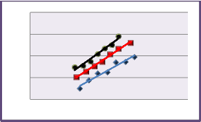
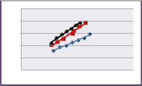
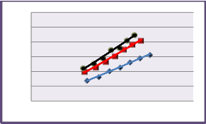
For more elucidation on the influence of y/d with different trapezoidal weir angle. The data model NO.(1-9) are reanalysis as a relations of the coefficient of discharge Cd with H/d for three different weir angle at particular y (=5,10, and 15), are presented in Fig.(6a,6b, and 6c).
It can be seen from these figures that the wider the angle, the higher the discharge coefficient Cd and the narrower the angle, the lower the Cd., Also, for the closer angles, the Cd values are not variant so much. This is due to the nearer flow area of the trapezoidal weirs when the
angles are closer as observed for the cases of (ɵ/2=30° and 45°). it is
clear that the difference in the Cd values between the cases of (ɵ/2=14° and 45° ) is high compared to the difference between those of (ɵ/2=45° and 30°).
Moreover, at smaller y/d the head over the weir increases, the contribution of the weir to the total combined flow increases and the data for the different angles deviate from each other reflecting the relative contribution of the weir flow to the total flow.
5- Development of new formulas.
The computer package (STATISTICA) was used to make analysis for equation (3) through a non-linear regression analysis.
In order to generalize the experimental results to some form of a relationship that includes the effects of main parameters. the results
formula which show the effect of trapezoidal weir angle (ɵ), and the
vertical distance (y) becomes:
0.56 0.57 0.58 0.59
Figure (7): Comparison of Equation (4) to Experimental Data
6- conclusions:
Under the limitations imposed on this investigation the following conclusions can be drawn.
As the vertical distance between the lower edge of the weir and the upper edge of the gate (y) increase the discharge coefficient increase.
when the trapezoidal weir angle increase for the same discharge the depth of flow over the weir decrease and the coefficient of discharge increases.
IJSER © 2014 http://www.ijser.org
International Journal of Scientific & Engineering Research, Volume 5, Issue 4, April-2014 - 812 - ISSN 2229-5518
0.60 cd
0.58
0.56
0.54
0.52
0.62 cd
0.60
0.58
0.56
0.54
2.0 3.0 4.0 5.0 6.0
1.5 2.5 3.5 4.5
0.62 cd
0.60
0.58
0.56
0.54
(a) for trapezoidal weir angle (ɵ/2=14˚)
0.62 cd
0.60
0.58
0.56
0.54
0.52
(a) for y=5 cm
2.0 3.0 4.0 5.0
2.0 3.0 4.0 5.0 6.0
(b) for trapezoidal weir angle (ɵ/2=30˚)
(b) for y=10 cm
0.65 cd
0.62
0.59
0.56
0.53
0.50
0.64 cd
0.62
0.60
0.58
0.56
0.54
0.52
2.0 3.0 4.0 5.0 6.0
2.5 3.5 4.5 5.5
(c) trapezoidal weir angle (ɵ/2=45˚)
4
Fig.(5):The variation of Cd with H/d for three different weir angle
(c) for y=15 cm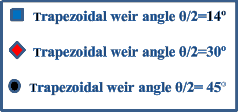
Fig.(6): Variation of Cd with H/d for three different trapezoidal weir angle .
LIST OF NOTATIONS:
IJSER © 2014 http://www.ijser.org
International Journal of Scientific & Engineering Research, Volume 5, Issue 4, April-2014 - 813 - ISSN 2229-5518
B: the gate width. (L) d: the gate height. (L) Cd: coefficient of discharge. -
H: total head (L) h: head of water through weir. (L) g: acceleration due to gravity . (LT-2) Qact: Total actual discharge. (L3T-1) Qg: Discharge through the gate. (L3T-1) Qtotal: Total theoretical discharge. (L3T-1) Qw: Discharge through the triangular weir. (L3T-1) Re: Reynolds number. – We: Weber number. - B: channel width. (L)
y: vertical distance between the lower edge of the weir and the upper edge of the gate opening (L)
θ :V-notch angle. (Degree )
References
1- Abdel-Azim M. Negm,(2002), “Discussion of Analysis and formulation of flow through combined v-notch-gate-device”,by Abdelaziz A. Alhamid, Journal of Hydraulic Research, Vol. 40,NO.6
755.
2- Abdel-Azim et al.,(2002) ,"Combined of Free Flow Over Weirs and
Below Gates ", Journal of Hydraulic Research,Vol.40,NO.3.
3- Ackers, A., W hite, W.R., Perkins, J.A. and Harrison, A.J.M,”Weirs and flumes for flow measurements, , John W iley & Sons, New York. (1978), Chapter 3, pp.44-85.
4- Ahmed, F.H.(1985), “Characteristics of discharge of the combined flow through sluice gates and over weirs”, J. Engineering and Technology, Iraq, Vol. 3, No. 2, pp. 49-63 (in Arabic).
5- Arora, K.R.,(2005), “ Fluid Mechanics Hydraulics and Hydraulic Machines”, Nai Sarak- Delhi, a.k. Jain for standard publishers Distributors, 2004, 1100 p.
6- Chow, Ven Te,(1983), “Open-Channel Hydraulics”, Japan, Mc
Graw-Hill book company, 20th printing , 661p.
7- H. A. M. Hayawi, G. A. M. Hayawi , Amal A. G. Alniami,( 2009) “Coefficient Of Discharge For A Combined Hydraulic Measuring Device” Al-Rafidain Engineering Vol.17 No.6 Dec.
8- H. A. M. Hayawi , Amal Abd Al-Ghani Yahia, G. A. M. Hayawi ,(
2008), “Free Combined Flow Over a Triangular Weir and Under
Rectangular Gate”, Damascus Univ. Journal Vol. (24)-No. (1).
9- amal M. V. Samani1 and Mehdi Mazaheri2,( March,2009) “Combined Flow over Weir and under Gate” , Journal of Hydraulic Engineering ASCE, Vol. 135, No. 3.
10- By Dae – Geun Kim, (March, 2007), “ Numerical Analysis of free flow past a sluice gate” , KSCE jornal of civil engineering, Vol.11, No. 2.
11- Kindswater,C.E., and Carter, R.W, (1959), “Discharge characteristics of rectangular thin plate weirs”, Trans. American Society of Civil Engineering, Vol. 124.
12- M. Piratheepan, N.E.F. W inston and K.P.P. Pathirana, ( 2006) ” Discharge Measurements in open channels using compound sharp – crested weirs” Journal of the Institution of Engineers, Sri Lanka, engineer - Vol. XXXX, No. 03, pp. 31-38.
13- Negm,A.M.,(2000), "Characteristics of Simultaneous Over Flow- Submerged Under Flow (Unequal Contraction) ", Engineering, Bulletin, Faculty of Engineering, Ain Shams University, Vol.35, No.1, March, pp.137-154.
14- P. Novak, A.I.B. Moffat , C. Nalluri and R. Narayanan, (2007) “Hydraulic Structures”, USA and Canada, Taylor &Francis, Fourth Edition .
15- USBR (1997), ” Water measurement manual”, United States Dept of the Interior, Bureau of Reclamation,3rd Edition, Denver.
IJSER © 2014 http://www.ijser.org
International Journal of Scientific & Engineering Research, Volume 5, Issue 4, April-2014
ISSN 2229-5518
814
l-EER ©2014