International Journal of Scientific & Engineering Research, Volume 6, Issue 2, February-2015 346
ISSN 2229-5518
Evaluation of Static Frequency Reuse
Techniques in OFDM Cellular Networks Using
SINR
Jayasankar.S
Abstract — The use of orthogonal frequency division multiple access (OFDMA) in Long Term Evolution (LTE) and W iMax cellular systems mitigates downlink intra-cell interference by the use of sub-carriers that are orthogonal to each other. Inter- cell interference, however, limits the downlink performance of cellular systems. In order to mitigate inter-cell interference, various techniques have been proposed. This paper examines one group of these techniques, static frequency reuse. We present a comprehensive comparison of Reuse-I, Reuse-3, fractional frequency reuse (FFR), and soft frequency reuse (SFR), with varying input parameters, such as inner radius and power ratios. System simulation is used to evaluate the overall system performance in terms of throughput and SINR are evaluated. In addition to the overall system performance, cell-edge user performance, whose performance is severely limited by interference from neighboring cells, for each technique is also evaluated.
Keywords - Frequency reuse, Channel, LTE, Soft frequency Reuse, capacity, throughput, SINR, Cell, eNode B.
—————————— ——————————
1 INTRODUCTION
merging wireless mobile systems, such as the 3GPP Long Term Evolution (LTE) and Mobile WiMax aim at provid- ing higher data rate and enhanced spectral efficiency. To
achieve that goal, they use orthogonal frequency division mul- tiple access (OFDMA) in their downlink air interfaces. OFD- MA offers a high spectral efficiency and a scalable bandwidth for cellular systems. It uses orthogonal frequency division multiplexing (OFDM), which is a multi-carrier modulation scheme that divides a frequency band into a group of mu- tually orthogonal narrow band sub-carriers whose bandwidth is smaller than the coherence bandwidth of the channel. The spectrum that is available for cellular systems is limited. Therefore, some form of mechanism is needed to use the available resource wisely and enhance the system capacity. One technique is to use the same frequency band in all the cells in a given cellular system. This is called frequency- reuse one approach (Reuse-l), since a band is reused over and over again across the cells. By using the same bands in different cells, the available spectrum can be reused, thereby improving spectral efficiency. The sub-carriers' orthogonality in OFDMA mitigates any inter-carrier interference among the sub-carriers. However, when using a Reuse-l scheme, co- channel interfer- ence (ICI) or inter-cell interference (ICI) will be incurred in adjacent cells that share the same spectrum. The ICI decreases the signal to interference and noise ratio (SINR), which causes a decrease in the spectral efficiency and data rate of the system. Hence, the need for interference mitigation schemes.The fre- quency collision in these cells results in severe inter-cell in- terfrence in the cell-edge users. To alleviate this problem, differ-
————————————————
• Jayasankar.S is currently pursuing M.Tech program in Communication engineering in Mahathma Gandi University, Kerala,India PH-
9447702249. E-mail: jayasankarsp@gmail.com
ent interference mitigation techniques have been studied.
The 3GPP categorizes these interference mitigation tech- niques for LTE into three: inter-cell interference randomization, inter- cell interference cancellation, and inter-cell interference co- ordination/avoidance. Inter-cell interference randomization techniques randomize interfering signals by cell-specific scram- bling, interleaving and frequency hoping to suppress interfer- ence and achieve frequency diversity gain. Inter-cell interfer- ence cancellation techniques perform interference mit- igation by either detecting and subtracting interfering signals from the desired signal or by employing multi-user detection at the re- ceiver to select the desired signal.
In this work, I consider inter-cell interference coordi- na- tion/avoidance techniques. These techniques require some form of coordination between different cells to restrict/allow re- sources in order to improve SINR and coverage . Inter-cell co- ordination techniques generally fall into two categories: stat- ic/dynamic , or centralized/distributed techniques. In static inter-cell interference coordination/avoidance techniques, allo- cated resource and power levels of transmitter for base stations are fixed. In the dynamic schemes, on the other hand, the re- sources are adaptively allocated and power levels adjustments are made depending on the channel condition and capacity de- mand of the cells. In centralized inter-cell interference coordina- tion schemes a centralized entity assigns resources to users while in distributed schemes cells based on the exchange of in- formation from other cells assign resources to users in a distrib- uted manner. Each of the above mentioned techniques have advantages and disadvantages, a discussion of which is beyond the scope of this paper.
Static inter-cell interference avoidance schemes are studied in this paper. Since the allocation of resources in the static schemes is fixed regardless of change in user distribution or channel condition, it is impossible to build resilient cellular
IJSER © 2015 http://www.ijser.org
International Journal of Scientific & Engineering Research, Volume 6, Issue 2, February-2015 347
ISSN 2229-5518
network structures which can be re-configurable adapting to their environment. By adjusting different parameters adap- tive- ly, a resilient network can be deployed. However, for that, a better understanding of the tradeoffs between the different ap- proaches as their settings are varied is needed. Therefore, in this paper, we present a comprehensive assessemnt of static inter- ference schemes, and evaluate the cell-edge, cell-center, and overall performance of the system in terms of the SINR, and spectral efficiency by adjusting different input parameters.
2 BACKGROUND
A hexagonal multi-cell OFDMA cellular network is considered in this paper. Each cell has a base station placed at the center of the cell serving a set of users within each cell. The smallest re- source allocated for a user is called a resource block (RB). Each resource block consists of 12 sub-carriers. The sub-carrier spac- ing is 15kHz making the bandwidth of each RB 180kHz. In this section of the paper, Bi (i= I, 2, 3,...)
represent the RBs for a given cell.
2.1 Reuse - n
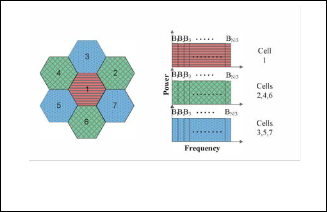
In this approach neighboring cells use different spectrum to avoid interference to users in their respective cells, The availa- ble bandwidth is split into n orthogonal sub-bands and each cell transmits on non interfering sub-bands. This ensures that the spectrum is reused at distant cells. n is called the frequen- cy reuse factor and can be written as n = i2 + ij +j2, for i, j є N. One example of Reuse-n is the Reuse-3. In Reuse-3, the whole frequency band is divided into three equal and orthogonal subbands, as shown in Fig. 1. The band is divided into three and allocated to the three groups. Accordingly, the total num- ber of resource blocks per cell is N/3 where N is the number of total resource blocks available for the system. Bl, B2, .., BN/3 represent the resource blocks in each cell. Reuse-n scheme provides improved inter-cell interference by avoiding using the same frequency bands in adjacent cells. By increas- ing the reuse factor, interference can be further reduced. How- ever, interference avoidance comes at the expense of band- width. In this scheme, each cell will have only a fraction of the available spectrum, resulting in a reduction in the number of resource blocks provided for users in each cell. This in turn will reduce the capacity and spectral efficiency of the system.
2.2 Fractional Frequency Reuse (FFR)
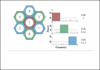
Fractional frequency reuse, originally proposed that, partitions the whole spectrum into two parts; namely, one with reuse factor 1, and one with reuse factor n, usually n = 3. The key idea behind FFR is to employ a reuse factor of unity for cell- center regions and a reuse factor of 3 for cell-edge regions. An example of FFR scheme is shown in Fig. 2.
In Fig. 2, the cellular service area of every cell is split into a
center zone and edge zone (the center zone is the shown in
circle). Correspondingly, the total spectrum is split into two regions, the center part where only users in the center zone are allowed to use, and the edge part, where only users in the edge zone are allowed to use. The total edge spectrum is fur- ther divided into three parts, corresponding to Reuse-3. B1, B2,
... ,BNi represent the resource blocks available for each center zone (inner region), where Ni is the total number of inner RBs. For the outer region, Bout represents the total number of RBs for each outer region in a cell. Therefore, the total number of outer RBs for the seven cell system presented in Fig. 1 is equal to 3Bout.
As a result of splitting the spectrum for inner and outer re-
gions of a cell so that interior users do not share any spectrum
with exterior users, significant inter-cell interference
reduction, particularly for cell-edge users, is achieved. How-

ever, the spectrum is underutilized in FFR since the cell-edge user can only use part of the total spectrum. In addition, the implementation of a reuse factor at a cell edge results in lower system throughput .
Fig. 2. FFR scheme. In FFR, the reuse factor for interior users is
1 and thereuse factor for exterior users is 3.
Fig. 1. Reuse-3 scheme. In this scheme no neighboring cells use the same spectrum.
2.2 Soft Frequency Reuse (SFR)
Unlike FFR, however, SFR reduces inter-cell interference without reducing spectrum efficiency. SFR splits the available band and RBs into two regions: cell-edge or outer band and cell-center or inner band. Correspondingly, users in a cell are grouped into two classes. The users closer to the center of the cell are grouped into cell-center or inner users, and the users close to the edge of the cell are grouped together and are called cell-edge or outer users. The cell-edge users are restrict- ed to use only the cell-edge band. The cell-center users have exclusive access to the cell-edge band, and with lower priority, they have access to the cell-edge band.
Fig. 3 illustrates a SFR deployment. In the figure, the cell is
divided into two zones; a center zone where all of the spec-
IJSER © 2015 http://www.ijser.org
International Journal of Scientific & Engineering Research, Volume 6, Issue 2, February-2015 348
ISSN 2229-5518
trum is available and a cell-edge zone where only a portion of the spectrum is available. The cell-edge band is transmitted with a higher power level whereas the cell-center band is transmitted with a reduced power level.
overall performance of the system, since spectral efficiency is proportional to the bandwidth. Therefore, in this work, in- stead of multiplying the total number of REs with the square of the ratio of inner radius to cell radius (α), it is multiplied by the ratio of α and an optimization parameter γ. Accordingly, for FFR Nin = N(α/γ)2, where α ≤ γ ≤ 1 and Nedge = ( N - Nin ) /n. For SFR, Nin = N(α/γ)2, and and Nedge = N - Nin.
3.2 Channel Model
We consider a cellular system with C base stations, each serv- ing U number of users. The signal to interference noise ration (SINR) of the received signal at user u using a RB b can be ex- pressed as
SINR
P s .G s
= b b
(1)
u ,b
N + ∑ P s .G s
Fig. 3. SFR scheme. In this scheme inner RBs transmit with a
higher transmit power than RBs used for cell-edge users.
0 b b i∈IC
3 SYSTEM MODEL AND ASSUMPTIONS
3.1 The LTE Downlink
In this work, we focus on the LTE downlink. For a given bandwidth, the bandwidth is split into sub-carriers, each hav- ing a smaller bandwidth also known as sub-carrier spacing ∆f
= 15kHz. A resource block (RB) is the smallest resource as- signed by a scheduler of a base station (eNodeB). An RB con- sists of 12 sub-carriers, therefore it has a total size of W =
180kHz in the frequency domain and 0.5ms in the time do- main. The more REs a user gets, the higher the bit-rate. A scheduling mechanism decides how many RBs a user gets at a given time.
The total number of RBs available for a given cell, Nc varies according to the scheme used. If N denotes the total RBs of an OFDMA system, then for Reuse-I , Nc = N. For Reuse-n, Nc = N/n. In FFR and SFR, the differentiation between inner and outer cell users is very important. One method to separate the two is to use their geographic location as a reference. Based on a user's distance from the center of a cell, if the distance is greater than a threshold radius, then user is an outer cell user (cell-edge user), if not, an inner cell user. Another method to differentiate between inner and outer users uses a geometry factor (SINR). Based on the measurement of a user's SINR, if
the SINR is greater than a certain threshold, then the user is an
where Pb s denotes the transmitted power by serving cell s on RB b, and Pbi., denotes the transmitted power by interfering cell i. IC is the set of all interfering cells in the cellular net- work. No represents the thermal noise power, and Gb and Gb represent channel gain between user u and the serving base station and interfering base stations respectively. The channel gain is composed of the path loss between the base station and u and is given as PL[dB] = 128.1 + 37.6 log10(d), where d is the distance, measured in kilometers, between a user and the cen- ter of the serving or interfering cell. where d is the distance, measured in kilometers, between a user and the center of the serving or interfering cell.
Interference occurs when the same RB is assigned to users in adjacent cells. In systems employing Reuse-n, adjacent cells do not interfere with each other. Instead, interference occurs when the same RB is assigned to users in non-adjacent cells which share the same spectrum with the cell (For example, in Fig. 2, cell-3 could interfere with cell-7, if they allocate their users the same RB). In FFR, interference occurs between adja- cent cells when the cells allocate the same RB for their inner users. The interference for cell-edge users follows the same principle as Reuse-n scheme.
In practical LTE systems, channel state information (CSI) is used and adaptive coding and modulation (ACM) is applied
in determining the throughput. For this work, however, we use Shannon's equation to calculate user throughput and it is given as
inner cell user, if not a cell-edge user. For this work, we use
Tu ,b = W . log2 (1 + SINRu ,b )
(2)
distance to differentiate between the two. The number of Res
is proportional to the inner radius of a cell for FFR and SFR.
The inner radius is used to distinguish between cell-center
where Tu,b is the throughput of user u on RB b, W is the bandwidth of b, and SIN Ru,b is the SINR of user u on b. The overall system throughput can be expressed as
users and cell-edge users, and is given as rin = αR, where R is U B
the radius of the cell, and α is ratio of the inner radius and the cell radius (0 < α < 1). Consequently, the number of inner and outer REs for FFR can be determined as Nin = N( rin /R) and
Ttotal
= ∑ ∑Tu ,b
u =1 b=1
(3)
Nedge = ( N - Nin ) /n where , n is the reuse factor (usually n
= 3). Similarly for systems employing SFR, Nin = N( rin /R)2,
and Nedge = N - Nin. However, from the simulation results
performed, it is understood that the value of α2 or (rin /R)2
which affects the number of RBs has a direct influence on the
where U is the total number of users in the system, and B is
the total number of resource blocks. Depending on the fre-
quency reuse scheme used, power allocated to each RB differs.
For Reuse-I, all RBs share equal power, meaning Pt = Pto-
tal/N, where N is the total number of RBs, and Ptotal is total
IJSER © 2015 http://www.ijser.org
International Journal of Scientific & Engineering Research, Volume 6, Issue 2, February-2015 349
ISSN 2229-5518
transmitting power. The power is evenly distributed among RBs. For Reuse-n, the total number of RBs available in a cell is Nc = N/n, and the transmitted power on each RB is given as Pt = Ptotal/ Nc. For FFR, the total number of RBs available in a cell is the sum of inner RBs (Nin) and edge RBs (Nedge), Nc
= Nin + Nedge. Transmitted power on each RB is given as Pt = Ptotal/Nc. SFR, edge or outer RBs and center or inner RBs transmit at different power levels. If the power on edge RBs is denoted as Pedge, and the power on inner RBs is denoted as Pin, then each can be calculated as
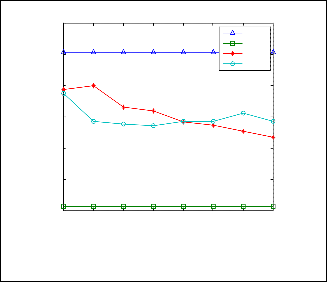
overall system throughput and SINR of the four schemes have been discussed. Fig. 4 presents results for the average overall system user throughput as a function of the ratio of inner ra- dius to cell radius (α) for Reuse-I, Reuse-3, FFR, and SFR. The number of RBs in each cell for Reuse-I was set to 50 and for Reuse-3 it was set to one third of 50 (approximately 17). For FFR and SFR, the parameter γ was set to γ = 0.8, the higher a value, the higher the number of inner RBs. Four values of al- pha are considered; 0.4, 0.5, 0.6, and 0.7. For SFR, the power
ratio β is set to 0.1.
Pedge

= nPtotal
N (1 + β (n −1))
(4)
The scheduling method used for all of the four schemes is Round Robin (RR) scheduling algorithm, where users take turns using RBs over a period of time (frame). For each a val- ue, the average user throughput for the cellular system is
Pin
= βPedge
(5)
computed and presented in Fig. 4. It can be seen that SFR pro-
where n is the reuse factor, and β is defined as the power
ratio. The power ration β has a range 0 ≤ β ≤ 1. If β = 1, the
scheme becomes a Reuse-I scheme where all the RBs, inner
and outer, transmit using the same power level.
4 SIMULAION RESULTS
In this work an LTE based cellular system is simulated. The simulation follows the LTE downlink described in section 3. A
19 cell system layout is simulated with users randomly dis- tributed in each cell. Each cell is assumed to have a base sta- tion with an omnidirectional antenna at the center of a cell.
vides higher throughput for smaller α values, where FFR pro-
vides higher throughput for larger alpha values. In the case of
SFR, the throughput decreases rapidly as a increases. That is
because as the ratio α increases, the number of inner users in-
creases leading to an increase in interference for cell-edge us- ers between adjacent cells. Similarly, the SINR for inner cell users decreases as the ratio increases.
Average inner cell user throughput for Reuse-I, Reuse-3, FFR, and SFR
7.5
Reuse-1
This can easily be extended to a sectorized cell layout, but since the purpose of this paper is to demonstrate the perfor- mance of different schemes, we focus only on the omnidirec- tional setting. The radius of each of the hexagonal cells is R = 2 km. The inner radius for FFR and SFR schemes is given as aR, where alpha takes values from 0 to 1 as discussed in section III. The total bandwidth of the system is 10 MHz. The spec- trum is divided into 50 RBs each having a bandwidth of 180
KHz. The total transmit power is set to 43 dBm. There are 608
users randomly placed over the 19 cell system.
7
6.5
6
5.5
5
4.5
4
Reuse-3
FFR SFR
Average user throughput for Reuse-1, Reuse-3, FFR, and SFR
13
Reuse-1
Reuse-3
12 FFR SFR
11
10
9
3.5
3
2.5
0.45 0.5 0.55 0.6 0.65 0.7 0.75 0.8
gamma
Fig. 5. Average inner cell user throughput for Reuse-I, Reuse-3, FFR, and SFR, with α = 0.4, and SFR power ratio β = 0.1 as a function of γ.
8
7
6
0.4 0.45 0.5 0.55 0.6 0.65 0.7 0.75
Alpha
Fig. 4. Average user throughput for Reuse-I, Reuse-3, FFR, and
SFR, with γ= 0.8, and SFR power ratio β = 0.1 as a function of α.
Previous studies have used a reference cell to evaluate dif- ferent frequency reuse schemes. In this work, however, we consider all the cells in a hexagonal layout, and evaluate the
Again, from Fig. 4 when α equals 0.4, the overall system throughput for SFR is even worse than for Reuse-I. It can be inferred that for smaller inner radius to cell radius ratio, sys- tem performance can be significantly enhanced by using SFR. Fig. 6.1 also shows that performance in terms of system throughput increases for FFR as α increases. That is because as a increases, the number of inner RBs increase and the increase in resource could mitigate the resource shortage by the in- crease in inner cell area, which increases the number of inner cell users. Another result to notice from the figure is the per-
IJSER © 2015 http://www.ijser.org
International Journal of Scientific & Engineering Research, Volume 6, Issue 2, February-2015 350
ISSN 2229-5518
formance of the Reuse-3 scheme. This scheme avoids interfer- ence at best by using a reuse factor of 3. However, since the entire cell uses just a third of the available RBs, its efficiency is very low. Reuse-I, on the other hand, uses the entire set of RBs. Nevertheless, the sever interference caused by reusing the available spectrum degrades the performance.
Average user throughput for Reuse-1, Reuse-3, FFR, and SFR
12
Reuse-1
Reuse-3
11 FFR SFR
10
5.5
5
9
Average cell-edge user throughput for Reuse-I, Reuse-3, FFR, and SFR
Reuse-1 8
Reuse-3
FFR 7
SFR
4.5
4
6
0.45 0.5 0.55 0.6 0.65 0.7 0.75 0.8
Gamma
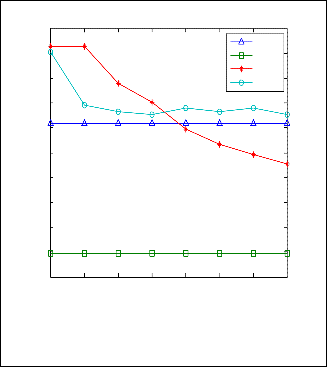
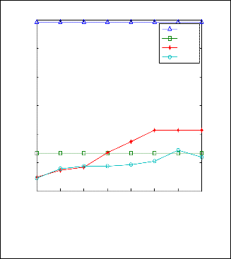
Fig. 7. Average user throughput for Reuse-I, Reuse-3, FFR, and SFR, with α = 0.4, and SFR power ratio β = 0.1 as a function of γ
3.5
3
2.5
0.45 0.5 0.55 0.6 0.65 0.7 0.75 0.8
gamma
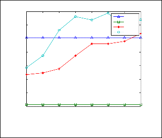
Fig. 6. Average cell-edge user throughput for Reuse-I, Reuse-3, FFR, and SFR, with α = 0.4, and SFR power ratio β = 0.1 as a function of γ
To see the effect of the change in parameter γ on the per- formance of FFR and SFR, a simulation is performed by keep- ing α constant at 0.4, and varying the value of γ. Fig. 5 and 6 present the results. For FFR and SFR, the average user throughput decreases rapidly as γ increases. The inner to cell radius ratio is kept constant, meaning the increase in γ de- creases the number of inner RBs. At γ = 0.4, all the available RBs are given to inner users, since , = a. In Fig. 6.2 we can see that as , increases the inner cell user throughput decreases because the number of inner RBs is reduced. However, from Fig. 6, it can be shown that the increase in , results in the in- crease in cell-edge user throughput. This is because of the in- crease in the number of outer RBs. Throughput for Reuse-I, and Reuse-3 remains constant as , does not have any impact on the RB allocation for the two schemes.
Fig. 7 shows the over all throughput of the users for fixed values of α,β. For FFR and SFR, the average user throughput decreases rapidly as γ increases. The inner to cell radius ratio is kept constant, meaning the increase in γ decreases the num- ber of inner RBs. At γ = 0.4, all the available RBs are given to inner users.
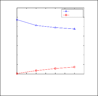
Another important parameter is β, used in SFR. To evalu- ate the performance of SFR under different β values, a simula- tion was performed for values 0.1 ≤ β ≤ 0.8, while fixing α at 0.4 and γ at 0.8. The result is presented in Fig. 7.The average throughput decreases for smaller β values as is seen in Fig. 6.5. This is due to the increase in interference, or decrease in SINR for cell-edge users as is shown in Fig.8. SINR for cell-edge de- creases because of the increase in transmit power on inner RBs as β increases. When the transmit power on inner RBs for a cell increases, SINR for innercell users increases by reducing the interference from adjacent cells. However, adjacent cell- edge users are highly affected by interference from the cell's inner RBs. The resulting decrease in SINR is slightly higher than the gain achieved by inner-cell users, from having their inner REs transmit at higher power, that it decreases the aver- age user throughput.
Average cell-edge, and inner-cell user SINR for SFR
33.5
inner-cell user cell-edge user
33.4
33.3
33.2
33.1
33
32.9
32.8
0.1 0.2 0.3 0.4 0.5 0.6 0.7 0.8
beta
Fig. 8. Average user throughput for SFR with α = 0.4, and γ =
0.8, as a function of power ratio β.
5 CONCLUSION
The PHYSICAL LAYER characteristics of LTE (Air interface)
IJSER © 2015 http://www.ijser.org
International Journal of Scientific & Engineering Research, Volume 6, Issue 2, February-2015 351
ISSN 2229-5518
has been simulated using MATLAB. Using MATLAB codes, studied about the generation and propagation, including the multiple input- multiple output (MIMO) system for LTE is evaluated for different number of transmitting and receiving antennas. Along with MIMO the channel capacity for down- link in LTE is calculated Reuse-3, fractional frequency reuse (FFR), and soft frequency reuse (SFR), that are used as inter- cell interference avoidance techniques in the OFDMA cellular downlink with varying input parameters, such as inner radius and power ratios. By considering these parameters, the per- formance in terms of average user throughput and SINR, av- erage cell-edge user throughput and SINR, and average inner- cell user throughput and SINR, has been evaluated in this work. The results obtained show that Reuse-l suffers the most interference while Reuse-3 achieves the lowest interference. Although all resources are used, because of its low average SINR for both cell-edge and cell-center users, Reuse-l provides low throughput. Reuse-3, on the other hand, avoids interfer- ence by reusing its RBs far apart and has the highest SINR. However, the smaller number of available RBs means lower average throughput. In SFR, smaller inner to outer cell ratio provides the highest average user throughput of all the tech- niques. However, cell-edge users suffer the most interference in SFR. It was also observed that for higher power ratios, aver- age SINR for inner users is increased, but the average cell- edge user SINR decreases, resulting in the decrease of the overall system average user throughput.
ACKNOWLEDGMENT
I wish to thank God Almighty, entire staff in my college and especially staffs from Department of Electronics and Commu- nication Engineering.
1-29,2013.
[9] R. Kwan and C. Leung, "A survey of scheduling and interference mitigation in lie," lECE, vol. 2010, pp. 1:1-1:10, Jan. 2010. [Online]. Available: http://dx.doi.org/IO.IISSI2010/273486
[10] M. Sternad, T. Ottosson, A. Ahlen, and A. Svensson, "Attaining both coverage and high spectral efficiency with adaptive ofdm downlinks," in Vehicular Technology Conference, 2003. VTC 20OJ-Fall. 2003 IEEE 58th, vol. 4, 2003, pp.
2486-2490 Vol.4.
[11] Ericsson, "R 1-0S0764: Inter-cell interference handling for E-UTRA," 3GPP TSG RAN WG] Meeting #42, 200S.
[12] C. He, F. Liu, H. Yang, C. Chen, H. Sun, W. May, and 1. Zhang, "Co-channel interference mitigation in mimo-ofdm system," in Wireless Communications, Networking and Mobile Computing, 2007. WiCom 2007. International Con- ference on, 2007, pp. 204-208.
[13] Huawei, " RI-0S0S07: Soft frequency reuse scheme for UTRAN LTE," 3GPP TSG RAN WG] Meeting #42, May 200S.
[14] T. Novlan, 1. Andrews, I. Sohn, R. Ganti, and A. Ghosh, "Comparison of fractional frequency reuse approaches in the OFDMA cellular downlink," in Global Telecommunications Conference (GLOBECOM 2010), 2010 IEEE,
2010, pp. I-S. [lS] 3GPP, TR36.942 V 8.2.0, "Evolved universal terristerial radio
[15] [15] Jayasankar.S, Surya Narayanan, Linu.R.Venu, Aswin Prasannan, Leksh- mi Gangadhar, “ LTE Access network simulation ” , IJLTET , July 2013
[16] Dodd.A.Z., Eylert.B., Scrase.A, ” The WiMAX (IEEE 802.16 standard)” Xi- chun Li, Abdullah Gani, Lina Yang, Omar Zakaria, Nor Badrul Anuar, “Mi- gration towards 4G wireless communications”.
[17] Toni Janevski , “ 5G Mobile Phone Concept , Consumer Communications and Networking Conference ”, 2009 6th IEEE.
[18] E. Dahlman , “ 3G Evolution: HSPA and LTE for Mobile Broadband “, 2nd ed., Academic Press, 2008
[19] Development of 3G mobile services , OECD Report, Sept. 2004.
REFERENCES
[1] S. Srikanth, P. Murugesa Pandian, and X. Fernando, "Orthogonal frequency division multiple access in WiMAX and LTE: a comparison," Communica- tions Magazine, IEEE, vol. SO, no. 9, pp. IS3-161, 2012.
[2] I. Katzela and M. Naghshineh, "Channel assignment schemes for cellular mobile telecommunication systems: a comprehensive survey," Personal Communications, IEEE, vol. 3, no. 3, pp. 10-31, 1996.
[3] J. Choi and S. Choi, "Multichannel sharing and joint detection for cell-edge users in downlink multicell OFDMA systems," Vehicular Technology, IEEE Transactions on, vol. 60, no. 4, pp. 1894-1898,2011.
[4] 3GPP, TR2S.814 V l.O.2, "Physical layer aspects for evolved UTRA,"January
2006.
[5] S. Cicalo, V. Tralli, and A. Perez-Neira, "Centralized vs distributed resource allocation in multi-cell ofdma systems," in Vehicular Technology Conference (VTC Spring), 2011 IEEE 73rd, 2011, pp. 1-6.
[6] Y. Yu, E. Dutkiewicz, X. Huang, M. Mueck, and G. Fang, "Performance anal- ysis of soft frequency reuse for inter-cell interference coordination in Ite net- works," in Communications and Information Technologies (ISCIT ), 20]0 In- ternational Symposium on, 2010, pp. S04-S09.
[7] R. Y. Chang, Z. Tao, J. Zhang, and C.-c. J. Kuo, "Dynamic fractional frequency reuse (D-FFR) for multicell ofdma networks using a graph framework," Wire- less Communications and Mobile Computing, vol. 13, no. 1, pp. 12-27, 2013. [Online]. Available:http://dx.doi.org/10.1002/wcm.1088
[8] A. Hamza, S. Khalifa, H. Hamza, and K. Elsayed, "A survey on inter-cell interference coordination techniques in ofdma-based cellular networks," pp.
IJSER © 2015 http://www.ijser.org