International Journal of Scientific & Engineering Research, Volume 6, Issue 4, April-2015 497
ISSN 2229-5518
Estimate Mathematical Model to Calculate the
View Angle Depending on the Camera Zoom
Heba Kh. Abass, Anwar Hassan M. Al-Saleh, Ali Abid D. Al-Zuky
Abstract— A mathematical model to estimate the camera view angle for a certain object has been found based on camera zoom where the fitting curves for the practical data of the view angles ( ![]() ) in the image plane which decreased with increasing distance (D) for each zoom number(Z) of the used camera were achieved. Then find the mathematical modeling equation that relates view angles (
) in the image plane which decreased with increasing distance (D) for each zoom number(Z) of the used camera were achieved. Then find the mathematical modeling equation that relates view angles ( ![]() ), real distance (
), real distance ( ![]() ) and zoom num- ber (Z) the comparison between theoretical estimation and practical result for the camera view angles and zoom number give a very good agreement between them where the estimated vertical and horizontal camera view angles very close to the real measurements.
) and zoom num- ber (Z) the comparison between theoretical estimation and practical result for the camera view angles and zoom number give a very good agreement between them where the estimated vertical and horizontal camera view angles very close to the real measurements.
Index Terms— View angle, camera resolution, mathematical model, estimated view angle.
—————————— ——————————
hroughout the centuries, people have tried to find a quicker and better way to capture the world around them. Drawing and painting were the most visible forms of this type of endeavor. Since not everyone is a skilled craftsman or artist when it comes to faithful renditions, instruments have been invented to make the rendering process easier. One of the ear- liest of these instruments is the camera obscure which literally means dark room built by Ibn Al-Haytham the `father of op- tics'. This tool started as a full-sized darkened room with a small opening on the end; it was used to observe solar eclipses and to aid artists in understanding perspective. Therefore, the first image capture devices required the observer to record the images by hand. Eventually, images projected through a small opening were miniaturized and improved through the use of lenses. These lenses made the image sharper and were able to resolve more details. Later, mirrors were added to a portable camera obscure, which facilitated the tracing of natural sub- jects. This invention became known as the camera Lucida [1]. Photography is the production of visible images, on a specially prepared surface, using light or radiation. The word comes from two Greek words that mean “writing with light”. In oth- er word it’s the art, science and practice of creating images by recording light or other electromagnetic radiation, either elec- tronically by means of an image sensor or chemically by means of a light-sensitive material such as photographic film
[2].
The cameras map surrounding space through optical systems (lenses, mirrors, filters, etc.) on to photo-sensitive devices (e.g., film, CCD, CMOS sensors). Various combinations of optical
————————————————
• Heba Kh. Abass, Baghdad University, College of Science for women, Department of Physics, physics_heba @yahoo.com.
• Anwar Hassan M. Al-Saleh,Al-Mustansiriyah University,College of
Science Department of Computer Science, anwar.hassan3@yahoo.com
• Ali Abid D. Al-Zuky,Al-Mustansiriyah University, College of Science, Department of Physics, prof.alialzuky@yahoo.com
elements lead to various types of cameras, to standard or non- standard ones. Sometimes it is an exigency raised from real world and sometimes just a challenge of intellectual curiosity to understand the geometry of various types of cameras [3, 4].
Many Researchers have studied the possibility of determining view angle camera and used the techniques of variety physical foundations. Here are reviews for some of these studies.
Steven Maxwell Seitz, (1997), study addresses the problem of synthesizing images of real scenes under three-dimensional transformations in viewpoint and appearance. Solving this problem enables interactive viewing of remote scenes on a computer [5].
Ming-Chih L. et al. (2010) presented an image-based system for measuring objects on an oblique plane based on pixel vari- ation of CCD images for digital cameras by referencing to two arbitrarily designated points in image frames, based on an established relationship between the displacement of the cam- era movement along the photographing direction and the dif- ference in pixel counts between reference points in the images [6].
Kouskouridas R. et al. (2012) proposed a novel algorithm for objects’ depth estimation; moreover, they comparatively study two common two-part approaches, namely the Scale Invariant Feature Transform SIFT and the speeded-up robust features algorithm, in the particular application of location assignment of an object in a scene relatively to the camera, based on the proposed algorithm. [7].
2 Camera Resolution
Camera resolution was described the ability of an imaging system to resolve detail of the object that is being imaged. An imaging system may have many individual components in- cluding a lens and recording and display components. Each of
IJSER © 2015 http://www.ijser.org
International Journal of Scientific & Engineering Research, Volume 6, Issue 4, April-2015 498
ISSN 2229-5518
these contributes to the optical resolution of the system, as will the environment in which the imaging is done [8]. Digital zoom (DZ) is a method of decreasing (narrowing) the appar- ent angle of view of a digital photographic or video image. The (DZ) is accomplished by cropping an image down to a centered area with the same aspect ratio as the original, and usually also interpolating the result back up to the pixel di- mensions of the original. It is accomplished electronically, with no adjustment of the camera's optics, and no optical reso- lution is gained in the process [9]. When comparing the image quality achieved by digital zoom with image quality achieved by resizing the image in post-processing, there's a difference between cameras that perform potentially lossy image com- pression like JPEG, and those that save images in an always lossless Raw image format. In the former case, digital zoom (DZ) tends to be superior to enlargement in post-processing, because the camera may apply its interpolation before detail is lost to compression. In the latter case, resizing in post- production was yields results equal or superior to digital zoom. Some digital cameras rely entirely on digital zoom, lacking a real zoom lens, as on most camera phones. Other cameras do have a real zoom lens, but apply digital zoom au- tomatically once its longest focal length has been reached. Pro- fessional cameras generally do not feature digital zoom [9].
A digital cannon camera (power shot A800 and IXUS digital compact camera, 2011), as shown in Fig. (1), with technical specifications tabulated in table 1, has been used in this study [10].

Fig. 1. Cannon camera (power shot A800 and IXUS digital compact cam- era).
= 13.5
Fig. 2. The image of object (picture).
First the object (picture) shown in Fig. (2), is placed in front of
the camera then the geometry of the scene sets object plane parallel to the image plane. For each zoom number (Z) of the camera (7, 8, 10, 12, 15 and 22) have been captured image for the object (with 10 Megapixels size) at different distances (D=
1 m to10 m) with changing 1m in each step. Then built an al- gorithm using MATLAB language to calculate the object’s length in pixels (picture’s height) for each captured image and this is performed by determine the length between two ends of the object (picture) manually using computer mouse. According to the following relationship: can be find image scale factor plane (Scf) [11].![]()
Where ![]() : object’s length in image pixel plane; and the
: object’s length in image pixel plane; and the ![]() : real object length in (cm).
: real object length in (cm).
By using eq. (1) can be computing vertical and horizontal sce- ne viewing in the capture image in (cm) based on the follow- ing sq.’s:![]()
![]()
![]()
Where ![]() and
and ![]() are the image length and width respectively in pixels. Then calculating the camera view angles in terms of H and W at each distance D and for each zoom number Z, according to the following eq.’s:
are the image length and width respectively in pixels. Then calculating the camera view angles in terms of H and W at each distance D and for each zoom number Z, according to the following eq.’s:![]()
Where D in a eq.’s (4) and (5) represents the distance between the cameras and the object![]() and
and ![]() : represent vertical and horizontal camera view angles respectively, as shown in Fig.(3).
: represent vertical and horizontal camera view angles respectively, as shown in Fig.(3).
IJSER © 2015 http://www.ijser.org
International Journal of Scientific & Engineering Research, Volume 6, Issue 4, April-2015 499

ISSN 2229-5518
![]()
(![]() ) for each captured images. Then draw the relation between zoom number (Z) and the view angles (
) for each captured images. Then draw the relation between zoom number (Z) and the view angles (![]() ) for different distances (D) see Fig.(4) and Fig.(5) . From these two figures can be shown that the relationship the camera zoom (Z) and the vertical and horizontal view angle ( ). Where can be see that the viewing angles ( ) are de- creased in non-linear relation with increased zoom number (z) for all distance between the camera and the object (D).
) for different distances (D) see Fig.(4) and Fig.(5) . From these two figures can be shown that the relationship the camera zoom (Z) and the vertical and horizontal view angle ( ). Where can be see that the viewing angles ( ) are de- creased in non-linear relation with increased zoom number (z) for all distance between the camera and the object (D).

![]()
Fig.4: The relation between zoom number (Z mm) and vertical view angle (


After cap different
Fig. 5: The relation between zoom number (Z mm) and horizontal view angle (
IJSER © 2015 http://www.ijser.org
International Journal of Scientific & Engineering Research, Volume 6, Issue 4, April-2015 500
ISSN 2229-5518
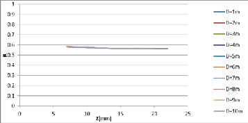
A graph between zoom number (Z) and the ra-
tio between (![]() ) and (
) and (![]() ) (eq.6) was plotted for each distance (D) in Fig. (6).
) (eq.6) was plotted for each distance (D) in Fig. (6).

![]()
Fig.6: The relation between (Z) and (R
This graph shows the relationship between the (Z) and the
ratio (R) between vertical and horizontal view angles for dif-
ferent distances (D). Can be observed that this ratio nearly
constant for all the different camera zoom (Z) and distances
(D). Where the ratio value approximately (0.58).
By using Table Curve “2D version 5.01” software to
estimate the best fitting equations between the viewing an-
gle (θi ) and the zoom number (Z), get the best fitting equation as follow:![]()
![]()
![]()
![]()
![]()
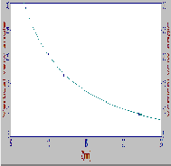
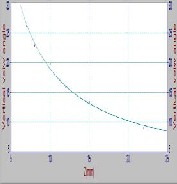
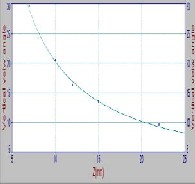
Where represent either or the es- timated fitting equation curves for some cas- es (D=1, 6, and 10) shown in Fig. (7), and for shown in Fig. (8) for different distance (D). Of the equation (7) can be note the In- verse relationship between the view angle and camera zoom.
(a): D=1 m
(b): D=6 m
(c): D=10 m
![]()
Fig.7: Fitting curve of vertical view angle ( with zoom (Z) at some different distance (a,b,c): D=
1,6,10 m respectively.
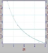
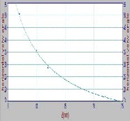
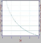

(a): D=1 (b): D=6 (c): D=10
Fig.8: Fitting curve of horizontal view angle ( with zoom (Z) at some different distance
(a,b,c): D= 1,6,10 m respectively.
International Journal of Scientific & Engineering Research, Volume 6, Issue 4, April-2015 501
ISSN 2229-5518

THE VALUES OF VERTICAL VIEW ANGLE ![]() WITH (Z) FOR EACH DISTANCE (D)
WITH (Z) FOR EACH DISTANCE (D)
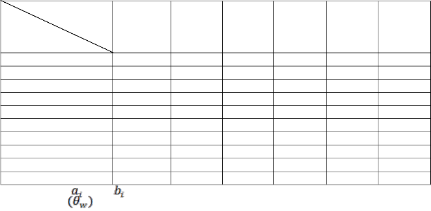
THE VALUES OF WIDTH VIEW ANGLE ![]() WITH (Z) FOR EACH DISTANCE (D)
WITH (Z) FOR EACH DISTANCE (D)
Zoom (Z mm)
Distance (Dm) 7 8 10 12 15 22
1 | 49.67 | 42.82 | 35.73 | 29.24 | 23.97 | 16.72 |
2 | 48.71 | 42.09 | 34.87 | 28.77 | 23.34 | 16.45 |
3 | 48.20 | 40.88 | 35.04 | 28.10 | 23.19 | 16.22 |
4 | 46.54 | 41.73 | 35.55 | 27.88 | 22.90 | 16.37 |
5 | 46.81 | 42.09 | 33.43 | 28.21 | 23.19 | 16.11 |
6 | 44.99 | 39.67 | 34.51 | 27.91 | 23.65 | 16.00 |
7 | 51.21 | 43.58 | 36.58 | 29.05 | 23.12 | 16.41 |
8 | 49.96 | 41.73 | 35.75 | 28.77 | 23.12 | 15.93 |
9 | 47.36 | 43.84 | 36.08 | 28.43 | 23.42 | 16.56 |
10 | 50.68 | 42.09 | 35.90 | 28.77 | 23.97 | 17.08 |
![]()
The two parameters , and , the notation (i either h or w) are tabulated in table (4) for and in table (5) for for all distances (D).
IJSER © 2015 http://www.ijser.org
International Journal of Scientific & Engineering Research, Volume 6, Issue 4, April-2015 502
ISSN 2229-5518
THE PARAMETERS OF THE fiTTING EQUATION OF VERTICAL VIEW ANGLE ![]() AS A FUNCTION OF (Z) FOR EACH DISTANCE (D)
AS A FUNCTION OF (Z) FOR EACH DISTANCE (D)
For checking the estimated models have been canceled the
practical results for distances D=2m and 3m from fitting pro- cess in order to determine the values theoretically from the estimated mathematical models eq.’s (5,6) and make a compar- ison between the practical and theoretical values. There is an excellent agreement between them, as shown in tables (4,
5).
![]()
![]()
The parameters of the fitting equation of horizontal view angle
(θw) as a function of zoom (Z) for each distance (D)
Distance (D) in m | aw- parameter | bw- parameter | r2- parameter |
1 | 1.55 | 335.22 | 0.999 |
2 | 1.47 | 329.12 | 0.999 |
3 | 1.60 | 323.15 | 0.996 |
4 | 2.18 | 315.84 | 0.993 |
5 | 1.81 | 317.69 | 0.999 |
6 | 3.60 | 293.19 | 0.993 |
7 | -0.20 | 357.05 | 0.997 |
8 | 0.41 | 342.28 | 0.995 |
9 | 1.84 | 327.82 | 0.992 |
10 | 1.40 | 337.47 | 0.994 |
10 | Average =1.57 | Average =327.88 | 0.994 |
We took the average and matching between the actual data in table (2) and (3) theory using the equation derived after com- pensation rate values represent either i saluting the ai, bi where i (h or w) After the compensation rate
values ai, bi and comparing the resulting values with practical
values.
IJSER © 2015 http://www.ijser.org
International Journal of Scientific & Engineering Research, Volume 6, Issue 4, April-2015 503
ISSN 2229-5518
Distance D (m) | Z (m m) | Prac- tical view angle ( | Esti- mate view angle ( | Abso- lute percent- age er- ror |
2 | 7 | 48.71 | 48.41 | 0.0062 |
2 | 8 | 42.09 | 42.55 | 0.0110 |
2 | 10 | 34.87 | 34.35 | 0.0149 |
2 | 12 | 28.77 | 28.89 | 0.0041 |
2 | 15 | 23.34 | 23.42 | 0.0035 |
2 | 22 | 16.45 | 16.47 | 0.0015 |
3 | 7 | 48.20 | 48.41 | 0.0044 |
3 | 8 | 40.88 | 42.55 | 0.0408 |
3 | 10 | 35.04 | 34.35 | 0.0196 |
3 | 12 | 28.10 | 28.89 | 0.0281 |
3 | 15 | 23.19 | 23.42 | 0.0100 |
3 | 22 | 16.220 1 | 16.4694 | 0.0154 |
From the results can be concluding the following points:
1. The estimated mathematical model to calculate the
viewing angles (![]() and
and ![]() ) for the digital can-
) for the digital can-
non camera (power shot A800 and IXUS digital com-
pact camera, 2011) can be status by:
2. This model gives high agreement between the practical value and stimated value.
[1]: Arnold G., “3D Lighting: History, Concepts, and Techniques”, Charles River Media, Inc., January 2000.
[2]: Spencer D. A., “The Focal Dictionary of
Photographic Technologies”, Focal Press, p.
454, 1973.
[3]: Branislav Mikulski,” Two-View Geome- try of Omni directional Cameras “, 2004, PhD Thesis, Department of Cybernetics, Faculty of Electrical Engineering Czech Technical Uni- versity in Prague. ttp://cmp.felk.cvut.cz.
[4]: T. Pajdla. Epipolar , “geometry of some non-classical cameras”. In Proceedings of the Computer Vision Winter Workshop, pages
223{233. Slovenian Pattern Recognition Soci-
ety, February 2001.
[5]: Steven Maxwell Seitz, 1997, “image based transformation of view point and scene appearance”, PhD thesis, computer science department, university of Wisconsin – madison.
[6]: Ming-Chih L., Chen-Chien H. and Yin-Yu L., “Distance and Angle Measurement of Distant Objects on an Oblique Plane Based on Pixel Variation on CCD image”, IEEE Instrumentation and Measurement Technology Conference (12MTC), pp. 318-322, Austin 3-
6 May, 2010.
[7]: Kouskouridas R., Gasteratos A. and
Badekas E., “Evaluation of two-part
algorithms for object’s depth estimation “, The
IJSER © 2015 http://www.ijser.org
International Journal of Scientific & Engineering Research, Volume 6, Issue 4, April-2015 504
ISSN 2229-5518
Institution of Engineering and Technology IET
Computer Vision, Issue 1, Vol. 6, pp. 70-78,
2012.
[8]:
http://en.wikipedia.org/wiki/Optical_resolutio n.
[9]:
http://en.wikipedia.org/wiki/Digital_zoom.
[10]: http://www.canon.co.uk.
[11]: Cyrus M., Edward S., Paul T. and
IJSER © 2015 http://www.ijser.org