International Journal of Scientific & Engineering Research, Volume 4, Issue 3, March 2013
ISSN 2229-5518
Development of Three phase to five phase Transformer using a novel technique
SUNIL KUMAR J1 SHALINI J2 Dr.P.G.V.SURESH KUMAR3 FIKADU WAKIJIRA4
Abstract:
There is rapid development in the power system applications in early from the 19th century in many areas like transmission, distribution and power system appliances. In the year 1970 there is rapid development in the sector of machines. In late 1970 the first five phase induction motor drive system was proposed the world. Since there is huge research attempts has been placed to develop the multiphase drive systems. The three-phase supply is available from the grid; there is a need to develop a static phase transformation system to obtain a multiphase supply from the available three phase supply. So this paper suggests a novel transformer connection idea to convert the three phase grid supply to a five phase fixed voltage by maintaining the constant frequency supply. Now days the use of five phase motor dive is ever-increasing in commercial purpose and in future also. To satisfy these there are having solutions first, implementation of six phase transmission. To implement this we have to change the three phase to six phase. This paper proposes the implementation of three phase to five phase transformer has been proposed. The five-phase transmission system can be investigated further as an efficient solution for bulk power transfer. The modeling of the five phase transformer is proposed and it is simulated in the Matlab environment.
Key words— Five phase, multiphase, three phase, transformer
I. INTRODUCTION
MULTIPHASE (more than three phase) systems are the focus of research recently due to their intrinsic advantages compared to their three-phase systems. The applicability of multiphase systems is investigate in electric power generation [1]–[5], transmission [6]–[9], and utilization [10]–[15]. The research on six-phase transmission system was initiated due to the rising cost of right of way for transmission corridors, environmental issues, and various stringent licensing laws. Six phase transmission lines can provide the same power capacity with a lower phase- to-phase voltage and smaller, more compact towers compared to a standard double-circuit three-phase line. The geometry of the six-phase compact towers may also aid in the reduction of magnetic fields as well [9]. The research on multiphase generators has started recently and only a few references are available [2]–[8]. The present work on multiphase generation has investigated asymmetrical six-phase (two sets of stator windings with 30 phase displacement) induction generator configuration as the solution for use in renewable energy generation.
Email:
sunilkumarjelledi@gmail.com1, Mob: +251926654388 aparanjishalu@gmail.com2, Mob: +91-9533993876 pendemsuresh@gmail.com3, Mob: +251911318620 fikaduwaki2010@gmail.com4, Mob: +251911156432
As far as multiphase motor drives are concerned, the first proposal was given by Ward and Harrer way back in 1969 [1] and since then, the research was slow and steady until the end of the last century. The research on multiphase drive systems has gained momentum by the start of this century due to availability of cheap reliable semiconductor devices. It is to be emphasized here that the multiphase motors are invariably supplied by ac/dc/ac converters. Thus, the focus of the research on the multiphase electric drive is limited to the modeling and control of the supply systems. Little effort is made to develop any static transformation system to change the phase number from three to n-phase. The scenario has now changed with this paper, proposing a novel phase transformation system which converts an available three-phase supply to an output five-phase supply.
Multiphase especially a 6-phase and 12- phase system is found to produce less ripple with a higher frequency of ripple in an ac–dc rectifier system. Thus, 6- and 12-phase transformers are designed to feed a multipulse rectifier system and the technology has matured. Recently, a 24-phase and
36-phase transformer system has been proposed for supplying a multi pulse rectifier system [16]–[17]. The reason of choice for a 6-, 12-, or 24-phase system is that these numbers are multiples of three
IJSER © 2013 http://www.ijser.org
International Journal of Scientific & Engineering Research, Volume 4, Issue 3, March 2013
ISSN 2229-5518
and designing this type of system is simple and straightforward. However, increasing the number of phases certainly enhances the complexity of the system. Up to now the even number of phases are available but there is no odd number of phases like 5,
7, 11 etc so we a contribution to do these odd number of phases.

Fig.01 Block representation of the proposed system
Fig.03 Proposed transformer winding connection
The usual practice is to test the designed motor for a number of operating conditions with a pure sinusoidal supply to ascertain the desired performance of the motor [38]. Normally, a no-load test, blocked rotor, and load tests are performed on a motor to determine its parameters. Although the supply used for a multiphase motor drive obtained from a multiphase inverter could have more current ripple, there are control methods available to lower the current distortion even below 1%, based on application and requirement. Hence, the machine parameters obtained by using the pulse width- modulated (PWM) supply may not provide the precise true value. Thus, a pure sinusoidal supply system available from the utility grid is required to feed the motor. This paper proposes a special transformer connection scheme to obtain a balanced five-phase supply with the input as balanced three phase. The block diagram of the proposed system is shown in Fig. 1. The fixed voltage and fixed frequency available grid supply can be transformed to the fixed voltage and fixed frequency five-phase output supply. The output, however, may be made variable by inserting the autotransformer at the input side.
The input and output supply can be arranged in the following manner:
a) Input star, output star;
b) Input star, output polygon;
c) Input delta, output star;
d) Input delta, output polygon.
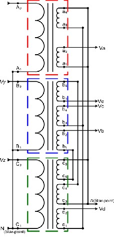
Fig.02 Proposed transformer winding arrangement.
Since input is a three-phase system, the windings are connected in a usual fashion. The output/secondary side connection is discussed in the following subsections.
IJSER © 2013 http://www.ijser.org
International Journal of Scientific & Engineering Research, Volume 4, Issue 3, March 2013
ISSN 2229-5518

sin(2𝜋)
5
0
2 𝜋
0 0 0


4 𝜋 0 0
� sin( )
15
sin( )
15
4𝜋
�..(10)
2𝜋
II. WINDING ARRANGEMENT FOR FIVE-PHASE
STAR OUTPUT
Three separate cores are designed with each carrying
one primary and three secondary coils, except in one core where only two secondary coils are used. Six terminals of primaries are connected in an appropriate manner resulting in star and/or delta connections and the 16 terminals of secondaries are connected in a different fashion resulting in star or polygon output. The connection scheme of secondary windings to obtain a star output is illustrated in Fig. 2. The construction of output phases with
0 0 0
sin � � sin( )
15 15
requisite phase angles of 72 degrees between each phase is obtained using appropriate turn ratios, and the governing phasor equations are illustrated in (1)– (10). The turn ratios are different in each phase. The choice of turn ratio is the key in creating the requisite phase displacement in the output phases.
𝑉𝑎
⎢𝑉𝑏 ⎥
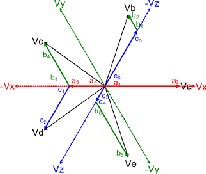
Fig.03phasor representation of the proposed transformer connection
In the transformer modeling the input phases are indicated with letters “x”, “y”, “z”, and the put phases are indicated with letters “A”, “B”, “C”, “D” and “E”. As illustrated in Fig.03, the output phase “A”is along phase “X”. The output phase “B” is the
sum of voltages in phse “c c ” and “b b ”, similarly
⎢ ⎥ 1
6 5 1 2
⎢ 𝑉𝑐 ⎥ =
⎢𝑉𝑑 ⎥
⎣ 𝑉𝑒 ⎦
𝜋


sin �𝜋� 𝑋
3
“C” is obtained from “a4a3” and “b3b4”. The output phase “D” is obtained by the phasor addition of voltages in “a4a3”and “c1c2” and similarly output phase “E” results from the phasor sum of the winding
voltages “c3c4” and “b6b5”. In this way the five

⎡ sin �3� 0 0 ⎤
phases are obtained from three phase to five phase.

⎢ 0 sin � 𝜋

� −sin 4𝜋 ⎥
15 15
⎢ 2𝜋 𝜋 ⎥


−sin � � sin � � 0
15 5
⎥ .(1)
III. SIMULATION RESULTS
⎢ 2𝜋
𝜋 ⎥


− sin � � 0 sin � �
15 5


⎢ 0 − sin 4𝜋� sin � 𝜋 �⎥
15 15
𝑉𝑎 =𝑉𝑚𝑎𝑥 sin (𝜔𝑡) … (2)

𝑉 =𝑉 sin (𝜔𝑡 + 2𝜋) … (3)
5

𝑉 =𝑉 sin (𝜔𝑡 + 4𝜋) … (4)
5

𝑉 =𝑉 sin (𝜔𝑡 − 4𝜋) … (5)
5

𝑉 =𝑉 sin (𝜔𝑡 − 2𝜋) … (6)
5
𝑉𝑥 =𝑉𝑚𝑎𝑥 sin (𝜔𝑡) … (7)

𝑉 =𝑉 sin (𝜔𝑡 + 2𝜋) … (8)
3

𝑉 =𝑉 sin (𝜔𝑡 − 2𝜋) … (9)
3
The model is shown in the below figure Fig.04. The designed transformer is at first simulated by using “simpowersystem” block sets of the Matlab/Simulink software. The inbuilt transformer blocks are used to simulate the conceptual design. The appropriate turn ratios are set in the dialog box and the simulation is run. Turn ratios are shown in Table I. The simulation model is depicted in Fig. 4 and the resulting input and output voltage waveforms are illustrated in Fig. 5. It is clearly seen that the output is a balanced five-phase supply for a balanced three-phase input. Individual output phases are, also, shown along with their respective input voltages
𝑉𝑥

�𝑉𝑦 � = 1 *
sin (2𝜋/3)
𝑉𝑧
IJSER © 2013 http://www.ijser.org
International Journal of Scientific & Engineering Research, Volume 4, Issue 3, March 2013
ISSN 2229-5518
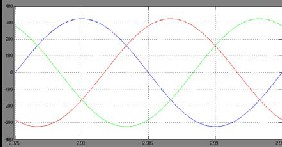
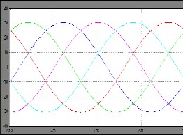
Fig.05 Output Voltage of the three phase transformer
Fig.06 Output Voltage of Five phase transformer
By examining the simulation graphs of the proposed model the output of the three phase transformer is 300V after converting the three phase to five phase the output is also coming as 300V.
The output voltages can be adjusted by simply varying the taps of the autotransformer. For balanced output, the input must have balanced voltages. Any
unbalancing in the input is directly reflected in the
output phases. The input and output voltage waveforms under no-load steady-state conditions
are recorded and shown in Fig.5 and Fig.6. On modeling these set of transformers it is very useful
for multiphase.
Fig.04 Simulation model of the three phase transformer to the five phase transformer
Tabel-01:
IV. Conclusion
IJSER © 2013 http://www.ijser.org
International Journal of Scientific & Engineering Research, Volume 4, Issue 3, March 2013
ISSN 2229-5518
This paper proposes a new transformer connection scheme to transform the three-phase grid power to a five-phase output supply. The connection scheme and the phasor diagram along with the turn ratios are illustrated. The successful implementation
of the proposed connection scheme is elaborated by using simulation. It is expected that the proposed connection scheme can be used in drives applications and may also be further explored to be utilized in multiphase power transmission systems.
REFERENCES
[1] E. E. Ward and H. Harer, “Preliminary investigation of an inverter-fed 5-phase induction motor,” Proc. Inst. Elect. Eng., vol.
116, no. 6, 1969.
[2] D. Basic, J. G. Zhu, and G. Boardman, “Transient performance study of brushless doubly fed twin stator generator,”
IEEE Trans. Energy Convers., vol. 18, no. 3, pp. 400–408, Jul.
2003.
[3] G. K. Singh, “Self excited induction generator research- a survey,” Elect. Power Syst. Res., vol. 69, pp. 107–114, 2004.
[4] O. Ojo and I. E. Davidson, “PWM-VSI inverter-assisted stand-
alone dual stator winding induction generator,” IEEE Trans Ind. Appl., vol. 36, no. 6, pp. 1604–1611, Nov./Dec. 2000.
[5] G. K. Singh, K. B. Yadav, and R. P. Saini, “Modelling and
analysis of multiphase (six-phase) self-excited induction generator,” in Proc. Eight Int. Conf. on Electric Machines and Systems, China, 2005, pp. 1922–1927.
[6] J. R. Stewart and D. D.Wilson, “High phase order transmission- a feasibility analysis Part-I-Steady state considerations,” IEEE Trans. Power App. Syst., vol. PAS-97, no.
6, pp. 2300–2307, Nov. 1978.
[7] J. R. Stewart and D. D. Wilson, “High phase order transmission- a feasibility analysis Part-II-Over voltages and insulation requirements,” IEEE Trans. Power App. Syst., vol. PAS-
97, no. 6, pp. 2308–2317, Nov. 1978.
[8] J. R. Stewart, E. Kallaur, and J. S. Grant, “Economics of EHV
high phase order transmission,” IEEE Trans. Power App. Syst., vol. PAS- 103, no. 11, pp. 3386–3392, Nov. 1984.
[9] S. N. Tewari, G. K. Singh, and A. B. Saroor, “Multiphase power transmission research-a survey,” Elect. Power Syst. Res.,
vol. 24, pp. 207–215, 1992.
[10] C. M. Portela and M. C. Tavares, “Six-phase transmission line-propagation characteristics and new three-phase
representation,” IEEE Trans. Power Del., vol. 18, no. 3, pp. 1470–
1483, Jul. 1993.
[11] T. L. Landers, R. J. Richeda, E. Krizanskas, J. R. Stewart, and
R. A. Brown, “High phase order economics: Constructing a newtransmission line,” IEEE Trans. Power Del., vol. 13, no. 4, pp.
1521–1526, Oct. 1998.
[12] J. M. Arroyo and A. J. Conejo, “Optimal response of power generators to energy, AGC, and reserve pool based markets,” IEEE Power Eng. Rev., vol. 22, no. 4, pp. 76–77, Apr. 2002.
[13] M. A. Abbas, R. Chirsten, and T. M. Jahns, “Six-phase voltage source inverter driven induction motor,” IEEE Trans. Ind. Appl., vol. IA-20, no. 5, pp. 1251–1259, Sep./Oct. 1984.
[14] K. N. Pavithran, R. Parimelalagan, and M. R. Krsihnamurthy, “Studies on inverter fed five-phase induction motor drive,” IEEE Trans. Power Electron., vol. 3, no. 2, pp. 224–235, Apr. 1988.
[15] G. K. Singh, “Multi-phase induction machine drive research—a survey,” Elect. Power Syst. Res., vol. 61, pp. 139–147,
2002.
[16] B. Singh and S. Gairola, “An autotransformer based 36 pulse controlled AC-DC converter,” Inst. Electron. Telecommun. Eng. J.
Res., vol. 54, no. 4, pp. 255–262, 2008.
[17] P. C. Krause, Analysis of. Electric Machinery. New York: McGraw- Hill, 1986.
[18] M. Jones, “A novel concept of a multi-phase multi-motor vector controlled drive system,” Ph.D. dissertation, Liverpool John Moores Univ., Liverpool, U.K., 2005.
[19] A. Iqbal, “Modelling and control of series-connected five- phase and six-phase two-motor drive,” Ph.D. dissertation, Liverpool John Moores Univ., Liverpool, U.K., 2006.
[20] H. M. Ryu, J. H. Kim, and S. K. Sul, “Analysis of multi-phase
space vector pulse width modulation based on multiple d-q spaces concept,” presented at the Int. Conf. Power Electronics and Motion Control IPEMC (CD-ROM Paper 2183.pdf.), Xian, China,
2004.
[21] O. Ojo and G. Dong, “Generalized discontinuous carrier- based PWM modulation scheme for multi-phase converter-
machine systems,” presented at the IEEE Ind. Appl. Soc. Annu. Meet. IAS (CD-ROM Paper no. 38P3), Hong Kong, China, 2005. [22] D. Dujic, M. Jones, and E. Levi, “Generalised space vector
PWM for sinusoidal output voltage generation with multiphase voltage source inverter,” Int. J. Ind. Elect. Drives, vol. 1, no. 1, pp.
1–13, 2009.
[23] M. J. Duran, F. Salas, and M. R. Arahal, “Bifurcation analysis of five-phase induction motor drives with third harmonic injection,” IEEE Trans. Ind. Electron., vol. 55, no. 5, pp. 2006–
2014, May 2008.
[24] M. R. Arahal and M. J. Duran, “Pi tuning of five-phase drives with third harmonic injection,” Control Eng. Practice, vol. 17, pp.
787–797, Feb.2009
Biographies:
Mr.Sunil kumar.J was born in Tirupathi, India. He received his B.Tech in Department of Electrical and Electronics from Anna Univeristy, Chennai, in 2006 and M.Tech from Sri Venkateswar University, Tirupathi, in

2011. Currently working as a Assistant Professor in Adama science and technology university, Adama. His research interests include Power Systems, Renewable Energy, Fuzzy Logic, Neural
Networks, Flexible AC Transmission System (FACTS). He is working as a reviewer for many journals like International Journal of Electrical Power & Energy Systems(Elesvier), International Journal of Scientific and Engineering Research, (IJ- ETA-ETS), Global Journal of Researches in Engineering,
United States, International Journals of Engineering & Sciences
IJSER © 2013 http://www.ijser.org
International Journal of Scientific & Engineering Research, Volume 4, Issue 3, March 2013
ISSN 2229-5518

Mrs. Shalini.J was born in Tirupathi, India. She completed B.Tech in 2010, M.tech in 2013 in Department of Chemical Engineering from SriVenkateswara University, Tirupati. Currently she is working as a Assistant professor in SKIT, srikalahasti, india. Her research interests include Chemical Reaction Engineering, Mass
Transfer, Process Dynamics and control, Neural Networks.

Dr.P.G.V.Suresh Kumar born in, India. He received his PhD in Computer Networks in 2007. Currently working as a Professor of Information Technology at Adama science and technology university, Adama. . His research interests include Computer Networking, Wireless networks, Grid Technology.

Mr. Fekadu wakjira born in, Ethiopia. He is having six years of working experience in Dept of electrical and computer engineering department
in Adama science and Technology
University. His educational background is communication engineering. He worked as a vice dean and presently working as a Dean for school of engineering in Adama Science and Technology University. His research interests
are communication systems, signal systems, Digital signal processing.
IJSER © 2013 http://www.ijser.org