

International Journal of Scientific & Engineering Research, Volume 4, Issue 6, June-2013
ISSN 2229-5518
672
![]()

![]()
The VLSI devices exhibit commendable characteristics of reconfigurability, which helps to develop an embedded system of desired features[1,2]. An innovative field of embedded system exhibits wide spectrum of applications particularly in the field of instrumentation. Designing of the instruments for precision measurement and control of various physical as well as chemical parameters such as electrical conductivity, dissolved oxygen, temperature, pH etc is the challenging job[3,4]. In case of physical parameter measurement, presently, the microcontroller of promising features are employed[5,6]. However, for such system the analog design is always off chip, which realizes the concept of system on board design. Ramya and Palaniappan[7] have designed an embedded system about PIC microcontroller for measurement and logging of the pH data and they reported the design of signal conditioners wired about LF 356. However, this operational amplifier needs two power supplies, +12V and -12V, due to which the grounding and shielding problem may arises. Moreover, this operational
amplifier has input impedance lower than that of standard pH
electrode. Helena et al have developed microcontroller based system for monitoring of water quality, which is suitable for indusial applications[8]. Misal et al have designed an embedded system for pH measurement, wherein the external memory chip is wired for data logging[9]. This realizes the theme of system of board design, wherein the complexity of interfacing and handshaking may be resulted[10]. The researchers are also reported the pH measuring embedded systems those are interfaced to the internet. However, the philosophy of temperature compensation is not introduced[11]. Chu et al[12] have reported microcontroller based embedded system for wireless measurement of pH using high electron mobility transistor as a sensor. It can be said that, the electronics system designed and presented are based on microcontrollers and are system on board. The hardware resources of microcontrollers provide limited configurability. Moreover, for system on board design the analog part of the DAS must be discretely wired. It is found that, the traditional BJT based operational amplifier, due to its low input impedance could not interfaced to the chemical sensors[13].
To overcome these limitations, the use of VLSI devices are recommended[14]. For VLSI devices like FPGA or CPLD, which ensures the configuration of digital cores only. The analog part of the system must be designed off the chip, which again results into system on the board. To avoid this problem and to ensure better integrability the field of Pro- ASIC design is emerged[15]. The Pro-ASIC devices comprise the core of the computing devices, with analog and digital cores with limited amount of configurability[16]. A revolution is taking place due to an innovative technology called mixed signal (analog + digital) array based VLSI design and
1
IJSER © 2013 http://www.ijser.org
International Journal of Scientific & Engineering Research, Volume 4, Issue 6, June-2013
ISSN 2229-5518
673
technology[17]. This technology emerges field of
Programmable System on Chip (PSoC). Programmable
system-on-chip (PSoC) of their own features have been designed by different venders and launched for dedicated mixed signal based embedded design[18]. The PSoC are having highly promising analog as well as digital cores exhibiting commendable configurability. The PSoC comprises the analog cores such as instrumentation amplifiers, programmable gain amplifiers (PGA), operational amplifiers, filters and digital cores such as Timers, counters, PLL, RAM, EEPROMs etc. along with the microcontroller core as computing unit[19]. Therefore, these PSoC devices provide better solution for designing of an embedded system, that realizes the system on-chip design.![]()
Based on PSoC1 of Cypress semiconductors, the Pulse oximeter is designed to ensure non-invasive measurement of blood oxygen[20]. Interfacing of pyroelectric sensor, environmental parameter sensors etc. are also reported by the researchers[20]. However, the reports on design of PSoC for precise measurement of pH are rather rare. Therefore, on deploying on-chip resources of PSoC devices a system is developed for precise measurement of temperature compensated pH of the solution and results of the implementation are interpreted in this paper.
An ubiquitous technology, mixed signal array based VLSI design, comprises both analog as well as digital devices of great configurability along with the core of computing device on one and single chip. This realizes the system on chip design. Such mixed signal based programmable System on Chips are provided by different vendors such as Cypress Semiconductors[21], Microsemi[22], Altera[23], Actel[24] etc. However, the programmable system-on-chip, Cypress make, is utilized for present system. The Cypress Semiconductor, USA Launched three generations of PSOCs, viz. PSoC1, PSoC3 and PSoC5. The PSoC1 demonstrate the basic philosophy of architecture of mixed signal device. However, the PSoC 3 and PSoC5 are having promising features required for mixed signal based system design[25]. The general architecture of the PSoC is depicted in figure 1.
Along with 8-bit microcontroller core (PSoC1), it comprises the arrays of programmable analog and digital building blocks and communication interfaces as well[26]. The signal translation devices like Analog to digital converter and Digital to analog converter, having programmable features, are also available. These PSoCs provide support for UART, SPI, and I2C communication protocols. The data RAM and flash EEPROMs are Harvard structured and are sufficient to program entire system on chip.
The PSoC5 architecture combines the industry-
leading ARM Cortex-M3 processor of powerful 32 bit
processing capacity, with flexible and programmable analog and digital subsystems[27]. The analog subsystems include high-precision, programmable analog resources such as a 20- bit Delta-Sigma ADC, 12 bit SAR ADC, DACs, TIAs, Mixers, PGAs with 25mA driving capacity, Op-Amps etc which can be configured to suit a designers unique needs. The digital subsystem includes enhanced programmable-logic based digital resources that can be configured as 8, 16, 24 and 32-bit timers, counters, and PWMs, as well as more advanced digital peripherals such as Cyclic Redundancy Check (CRC), Pseudo Random Sequence (PRS) generators, and Quadrature decoders. The new architectures also support a wide range of communications interfaces, including Full-Speed USB, I2C, SPI, UART, CAN, LIN, and I2S as well. The current consumption for PSoC5 in sleep mode is whereas it is
2mA in active mode operated at 6 MHz. The new PSoC5 architecture meets the demands of extremely low power applications by delivering the industry’s widest voltage range from 5.5V down to 0.5V along with low 300nA current. It offers programmable routing, allowing any signal, whether analog or digital, to be routed to any general-purpose I/O to ease circuit board layout. This capability includes the ability to route LCD Segment Display and Cap Sense signals to any GPIO pin. The PSoC5 operates at configurable clock of 1 to 66
MHz with internal PLL. However, the external clock of 32
KHz is used to avoid the jitter in the frequency.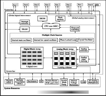
The PSoC5 architecture is powered by the revolutionary PSoC Creator Integrated Development Environment (IDE), which introduces a unique schematic- based design capture along with fully tested, pre-packaged analog and digital peripherals easily customizable through
2
IJSER © 2013 http://www.ijser.org
International Journal of Scientific & Engineering Research, Volume 4, Issue 6, June-2013
ISSN 2229-5518
674
user-intuitive wizards and APIs to meet specific design
requirements[28]. PSoC Creator enables engineers to design
the way they think and dramatically shorten time-to-market, and allow a seamless transition between 8-bit PSoC 3 designs and 32-bit PSoC5 designs with pin and API compatibility[29].
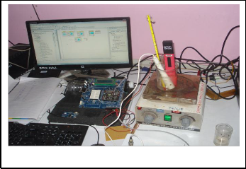
It is found that the programmable system-on-chip PSoC, demonstrate high degree of both static as well as dynamic configurability[30]. Two types of parameters, global parameter and device parameter, must be configured. The global parameters, such as clock frequency, power supply, reference voltages, grounds etc. must be configured in the beginning. Figure 2 represents cypress PSoC5 development board.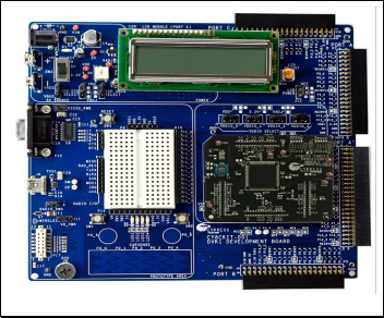
The analog cores of the mixed signal based PSoC are based on the Principle of Switching Capacitor (SC), which is further employed for configuration of the resistors required for analog design[31]. The principle of operation of SC circuits is based on the fact that the movement of charge stored on a capacitor can be approximated the average current through a resistor[32].
Analog circuit design requires the components like resistor, capacitor, etc. In CMOS technology the capacitor can be integrated. However, to achieve the design of programmable resistor an alternative method of switching capacitor is adopted. According to the principle, switching capacitor is used as configurable resistor. The description of this principle is as follows. Figure 3 shows charge movement through a resister and through a switched capacitor. Following equation represents the current flow from source to ground through the resister as shown in figure 3.
i = V/R …(1)
M1 M2
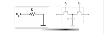
In figure 3 when the Φ1 switch is closed and the Φ2 switch is opened. Then capacitor charge to the full potential V. The equation for the amount of stored charge is
Q = CV …(2)
Where, the capacitance C is a constant. Thus for given capacitor, the stored charge Q is proportional to V, the applied potential.
When the switch Φ1 is opened and switch Φ2 is closed, the stored charge moves to ground. For each sequential pair of switch closures, a quantum of charge is moved. If the switches are opened and closed at the rate of fs, the charge quanta also move at this rate. The following equation shows that the repetitive movement of charge is equivalent to an average current given by
Iaverage = Q/T = Qfs = CVfs …(3)
Unlike the resistor the current is not actually a continuous movement of charge. The charge moves in quanta. Following equation shows that a switched capacitor is equivalent to a resistor when they have equivalent ratio of voltage drop verses delivered current.
Requivalent = V/Iaverage = 1/Cfs …(4)
Hence the equivalent resistance is inversely proportional to the capacitance and the switching frequency and can be altered merely by changing the switching frequency. The larger the capacitance C, the larger the charge quanta, resulting in more current for the same value of fs and thus a smaller equivalent resistance. Increasing frequency fs causes more quanta to be transferred per unit of time, resulting in a higher current and lower effective resistance.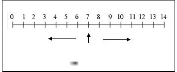
Figure 3 presents a switched capacitor circuit that
+414 mV 0 mV -414 mV
Acid Caustic
Neutral
3
IJSER © 2013 http://www.ijser.org
International Journal of Scientific & Engineering Research, Volume 4, Issue 6, June-2013
ISSN 2229-5518
675
uses the transistor M1 and M2 to implement the switches Φ1
and Φ2. If the clock signal Φ1 is high, then gate to source
voltage Vgs of transistor M1 is larger than the threshold voltage of the transistor. Therefore, the transistor is conducting and acts as closed switch. During this time clock Φ2 is low hence the gate to source voltage Vgs of transistor M2 is lower than its threshold voltage and this transistor is OFF i.e. the switch is open. The circuit operation is similar for clock Φ1 low and clock Φ2 high. But now transistor M1 is OFF and transistor M2 is ON. PSoC have two types of programmable switched capacitance blocks viz., type C and type D[31]. The functionality of each SC block can be programmed as inverting, non-inverting amplifiers, integrators and comparators.
In present programmable system on chip, developed for measurement of pH of different aqueous solutions, the pH sensor is only off chip. Rest of hardware components are on chip. The standard pH glass electrode is deployed, which produces the potential in the range of +414 mV to –414 mV, for the pH range from 0 to 14 (Figure 4). That means the coefficient is 59.16 mV per pH. The pH is defined as the negative logarithm of the hydrogen ion concentration. It is expressed mathematically as:
pH = – log [H+] . ...(5)
Where, [H+] is hydrogen ion concentration. As shown in the equation 5, pH is a logarithmic function. A change of one pH unit represents a 10-fold change in concentration of hydrogen ion. In a neutral solution, the [H+] = 1×10⁻⁷. This represents a pH of 7.
The pH value of the solution is never remains constant. It is highly sensitive to the environmental temperature. This is due to the fact that the emf produced by the pH electrode is sensitive to the temperature. It is expressed by the Nernst equation[33,34],
E = E0 + (2.3RT/nF) log [H+] ...(6)
Where, E is total potential difference (mV), R is gas constant, T
is temperature in K, n is number of electrons, F is Faraday’s![]()
constant and H+ is concentration of hydrogen ion. The expression 6 is implemented in the software for temperature compensation. The entire term "2.3RT/nF" is called the Nernst factor, or slope factor[33]. This term provides the change in the resultant potential due to variation in the temperature. At room temperature this factor equals to 0.05916, where for hydrogen ion n = 1. For every pH unit the potential should be changed by 59.16 mV. Moreover, this change in emf is also due to change in Nernst factor. The variation of emf produced by pH electrode can be illustrated with isothermal graph (Figure 5). Figure 5 is the graph of emf against pH values plotted at room temperature 29oC. From this graph it is found that the emf and hence pH values are temperature dependent. Thus, the emf and hence pH values provided by the pH electrode are sensitive to the temperature. Therefore, compensation of the pH is also considered while designing of present system on chip.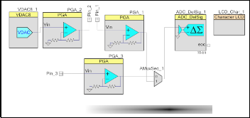
The present system-on-chip is designed by deploying the development board of PSoC5, wherein the PSoC device CY8C5588AXI-060 is incorporated[28]. It ensures co-design of the hardware as well as software. As discussed earlier, the Cypress has provided the smart IDE, called PSoC creator 2.1, using which one can design and integrate the system on the chip. It realize the techniques of placing, configuration, routing and integration of the devices on a single chip. Employing PSoC creator 2.1, the system is designed. It comprises both hardware and software. Hardware part of the system is depicted in figure 6.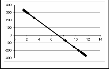
The system is designed for measurement of two
pH parameters, pH as well as temperature (Figure 6).
The pH electrode is externally interfaced at Pin_1 and Pin_2 of PSoC device. These two pins are configured for analog only with high impedance analog device mode[31]. Therefore, it is able to read the emf of pH electrode precisely. The pH electrode is excited with 420 mV, constant voltage source, which is obtained by introducing VDAC core into the system. This VDAC is configurable digital to analog converter
4
IJSER © 2013 http://www.ijser.org
International Journal of Scientific & Engineering Research, Volume 4, Issue 6, June-2013
ISSN 2229-5518
676
core. The excitation potential is also buffered by employing a
programmable gain amplifier (PGA_2), which is configured to
the unity gain. As, shown in the figure 6, the resulting pH electrode potential is read through PGA_1. This PGA also configured to unity. Thus, the pH electrode is operating among two buffers. The electrochemical potential produced by the pH electrode is digitized by availing on-chip analog to digital converter. Analog sequential multiplexer (AMuxSeq_1) is used to multiplex these two signals. It is configured as 2 to 1 multiplexer. The operation of the multiplexer is controlled through software.
Another parameter, the temperature, is also
measured for which the circuit is designed and integrated into the same system-on-chip. A precision, monolithic temperature sensor, AD590, is deployed to design the system-on-chip for temperature measurement. This sensor provides the current output with, temperature coefficient as /K, which is further converted into voltage form (1mV/K) by passing the same into 1KΩ resistor. The temperature dependent analog data is read through the buffer configured using PGA_3 and applied to ADC through analog sequential multiplexer (AMuxSeq_1).
The PSoC5 is characterized with the configurable resolution ADC called ADC. It can be placed and configured to any desired resolution. For present system, it is configured to 10-bit resolution.
It is to be noted that PSoC5 comprises the 16 character X 2 lines LCD block, which when placed can be directly routed to the off-chip smart LCD. All IP cores are configured by employing the resources provided by PsoC creater 2.1.
The firmware required for this System-on-Chip is co- designed by using PsoC creater tool. The initialization and accessing of all cores are done through the firmware.![]()
Adopting the procedure described by the Cypress [28], and on successfully building of the project, the “devich.h” file is created and programmed into the target device to ensure development of system-on-chip for dedicated application, temperature compensated pH measurement.
Deploying promising features of Cypress PSoC5, CY8C5588AXI-060, a mixed signal based system-on-chip is designed for measurement of pH as well as temperature of the solution and represented in figure 7.
In fact, the analog part of System-on-Chip provides the emf for both parameter, temperature as well as pH. Therefore, it is the need to calibrate the system to provide output in respective units.![]()
For calibration to the temperature data in degree centigrade, the sensor is exposed to temperature from 25oC to
5
100oC and emf data is collected. Employing Least Squares procedure the data is fitted to straight line. The graph of observed emf against applied temperature is shown in figure
8. The empirical relation obtained is given by (equation 6).
Vo = 1.0034 T + 0.9218 …(6)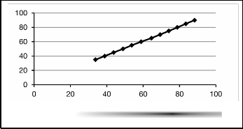
Where, Vo is observed emf in mV and T is the applied voltage in oC.
Observed temperature (oC)
This empirical relation is used in the firmware for calibration. Thus, the system is standardized to temperature in degree centigrade. On implementation, it is found that temperatures shown by standard thermometer and that of obtained from system under the investigation are closely matched. This supports the reliability in the design.![]()
For the calibration of the system to pH scale, two point calibration process is adopted [35,36]. The buffer solutions of standard pH = 4 & pH = 7 are prepared and used to measure emf produced by the system at temperature 270C. On fitting this data to straight line, an empirical relation is obtained [Equation 7].
Eobs = (52.282 × pH) + 84.906 …(7)
IJSER © 2013 http://www.ijser.org
International Journal of Scientific & Engineering Research, Volume 4, Issue 6, June-2013
ISSN 2229-5518
677
Therefore,
pH = (0.0191 × Eobs) – 1.624 …(8)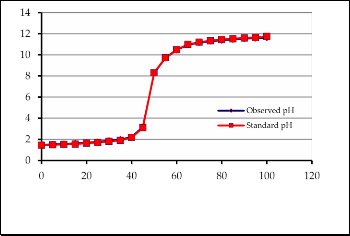
Where, Eobs is the observed emf in mV. This expression [Equation 8] is employed in the firmware, which converts the observed emf in to pH value at room temperature (270C). Thus the system on chip is calibrated to pH scale. It provides observed pH very precisely. The performance of the system
Volume of base added (ml)
described by the Nernst expression [34]. Therefore, to
determine temperature compensated pH values the Nernst
expression is reduced to
EC = ET – 0.00019841 × T × pH …(9)
Where, EC is the temperature compensated emf in mV and ET is the emf at temperature T in mV. Therefore, the temperature compensated pH is given by
pH = EC/59.16 …(10)
Where, 59.16 mV/T is the standard coefficient.
This temperature compensated emf (EC) is availed in the firmware to calculated pH value. Thus pH value of the solution is Temperature compensated. The temperature dependant pH values, compensated as well as uncompensated are measured for the solution of different pH and plotted against temperature in 0C and depicted in figure
10-a and figure 10-b.
under investigation is compared with standard pH meter,
Hanna Instruments, HI96107 model. Moreover, the system under investigation is implemented to measure pH of the different solution. The process of titration of base against acid is carried out at room temperature and the pH values shown by the system are plotted against volume (ml) of base and presented in figure 9. Moreover, pH values are also measure by standard pH meter and presented in figure 9. On close inspection of figure 9, it can be said that, the pH values shown by the system under investigation and that of obtained from standard pH meter show close agreement. This supports the accuracy in the system on chip design.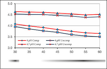
It is found that, the pH depends upon temperature of the solution. Therefore, compensation of the pH is essential. The temperature dependence of pH of the solutions is
Observed temperature (oC)
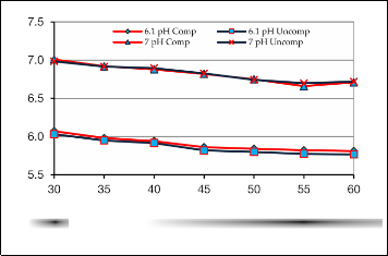
The temperature compensated pH values of the solutions measured against temperature and plotted (figure
10). On inspection of figure 10, it is found that the values of the pH decrease with increase in the temperature. Such decrease in the pH values with increase in the temperature is also reported by Helena et al [8]. This decrease in the pH values may be attributed to the ionic dissociation at high temperature. The figure 10 also shows difference between compensated and uncompensated pH values for pH = 4, 4.7,
6.1 and 7, for temperature within the range from 30oC to 60oC. The rate of this deviation with temperature (∆pH/oC) is also obtained. This deviation is almost constant, within range of investigation.![]()
Observed temperature (oC)
Based on Cypress PSoC5, the system-on-chip is designed to measure temperature compensated pH of the solution. The present system ensures the mixed signal based
6
IJSER © 2013 http://www.ijser.org
International Journal of Scientific & Engineering Research, Volume 4, Issue 6, June-2013
ISSN 2229-5518
678
IJSER © 2013 http:1/www.ijser.org