
International Journal of Scientific & Engineering Research, Volume 3, Issue 11, November-2012 1
ISSN 2229-5518
Design of Microcontroller Based Static VAR Compensator
Rajib Baran Roy
Abstract—The change in system voltage and frequency with changing load creates problem in power system stability. For the sake of system stability and reliability, the reactive power compensation is essential for flexible AC transmission system (FACTS). T he variation of reactive power causes impact on the generating units, lines, circuit breakers, transformers, relays and isolators. However the reactive power can be compensated from the generating unit by changing the excitation of the generator. But if the total reactive power is feed only by the generation unit, it will lower the maximum real power capacity of generator. Moreover the additional current flow associated with reactive power can cause increased losses and excessive voltage sags. Therefore the local VAR compensator which is comprised of shunt reactors are used in transmission and distribution system for reactive power compensation. The conventional electro-mechanical reactive power compensator is not suitable for its slow switching speed which cannot commensurate with the rapid changing system load. The electronic reactive power compensator uses fast switching devices like thyristor which provides faster switching option than that of the conventional relay. The static VAR compensator (SVC) is the combination of thyristor switched capacitor (TSC) and thyristor controlled reactor (TCR) which is widely used in HVAC (High Voltage AC) and HVDC (High Voltage DC) systems. The design of the microcont roller based SVC with harmonics suppressor is discussed in this paper. Harmonics are generated which may unbalanced the system due to rapid switching of the connected reactor with the live transmission line. Therefore the harmonics suppressor is used in the proposed design. For precise switching of the thyristor, microcontroller is used which adds an significant feature of this designed SVC.
Index Terms— Reactive Power Compensation, Flexible AC Transmission System, VAR Compensator, Thyristor Switched Capacitor, Thyristor Controlled Reactor, High Voltage AC System, High Voltage DC system, Harmonics Suppressor
—————————— ——————————
HE VAR compensation is defined as the management of reactive power to improve the performance of ac power systems [1]. The concept of VAR compensation embraces VAR compensation is defined as the management of reactive power to improve the performance of ac power systems. The concept of VAR compensation embraces a wide and diverse field of both system and customer problems, especially related with power quality issues, since m The wide and diverse field of both system and customer problems, especially related with power quality issues, since most of power quality problems can be attenuated or solved with an adequate control of reac- tive power [1]. In general, the problem of reactive power com- pensation is viewed from two aspects, load compensation and voltage support. In load compensation the objectives are to increase the value of the system power factor, to balance the real power drawn from the ac supply, compensate voltage regulation and to eliminate harmonics produced by large and fluctuating nonlinear industrial loads [2, 3]. The voltage sup- port is generally required to reduce voltage fluctuation at a
given terminal of a transmission line.
The reactive power compensation in transmission systems
also improves the stability of the ac system by increasing the
maximum active power that can be transmitted. It also helps
to maintain a substantially flat voltage profile at all levels of
power transmission, it improves HVDC (High Voltage Direct
Current) conversion terminal performance, increases trans-
————————————————
mission efficiency, controls steady-state and temporary over- voltage and can avoid disastrous blackouts [4,5,6]. Series and shunt VAR compensation are used to modify the natural elec- trical characteristics of ac power systems. Series compensation modifies the transmission or distribution system parameters, while shunt compensation hangs the equivalent impedance of the load [1, 7]. In both cases, the reactive power that flows through the system can be effectively controlled for improving the performance of the overall ac power system which is es- sential for FACTS (Flexible AC Transmission System).
Traditionally, rotating synchronous condensers and fixed or mechanically switched capacitors or inductors have been used for reactive power compensation. However, in recent years, static VAR compensators employing thyristor switched capacitors and reactors to manage the reactive power of the power system [7, 8, 9]. Also, the use of self-commutated PWM converters with an appropriate control scheme permits the implementation of static compensators capable of generating or absorbing reactive current components with a time re- sponse faster than the fundamental power network cycle [10,11,12]. Based on the use of reliable high-speed power elec- tronics, powerful analytical tools, advanced control and mi- crocomputer technologies, the FACTS has been developed and represent a new concept for the operation of power transmis- sion systems [13, 14]. In these systems, the use of static VAR compensators with fast response times laid an important role, allowing increasing the amount of apparent power transfer through an existing line, close to its thermal capacity, without compromising its stability limits. These opportunities arise through the ability of special static VAR compensators to ad- just the interrelated parameters that govern the operation of transmission systems, including shunt impedance, current,
IJSER © 2012
International Journal of Scientific & Engineering Research, Volume 3, Issue 11, November-2012 2
ISSN 2229-5518
voltage, phase angle and the damping of oscillations [15]. The most common method for this compensation is to add capaci- tor banks to the system. Capacitors are attractive because they are economical and easy to maintain. Not only that, they have no moving parts, unlike some other devices used for the same purpose. Using shunt capacitors to supply the leading cur- rents required by the load relieves the generator from supply- ing that part of the inductive current [2]. The shunt capacitor is generally required when the system inductive load increases, thereby the system voltage and frequency decreases with in- crement of lagging reactive power. On the other hand when the system inductive load decreases or at no load condition, the system voltage and frequency increases with decrement of lagging reactive power then the shunt inductor bank is re- quired for the increment of lagging current. The connected capacitor and inductor is beneficial for the system which pro- vide reactive power support, voltage profile improvements, line and transformer loss reductions, release of power system capacity and reduction of energy loss. Low voltage and fre- quency may cause power losses in the system, low perfor- mance in the appliances and industrial machineries. Similarly overvoltage damages the electrical appliances and hampers the operation of rotating machines. These problems can be eliminated by compensating reactive power using capacitor and inductor.
The study of system stability is essential for determining the impact of disturbances on power system. The effect of faults on the system is determined from transient and steady state condition. The transient stability studies are very commonly undertaken by electric planning departments responsible for ensuring proper dynamic performance of the system. The sys- tem models used in such studies are extensive because present day power systems are vast, heavily interconnected system with hundreds of machines which can interact through the medium of their extra-high-voltage and ultra-high-voltage networks [1]. These machines have associated excitation sys- tems and turbines-governing control system which in some but not all cases are modeled in order to reflect properly cor- rect dynamic performance of the system.
A power system is in a steady-state operating condition if all the measured (or calculated) physical quantities describing the operation condition of the system can be considered con- stant for purpose of analysis. When operating in a steady-state condition, a sudden change or sequence of changes occurs in one or more of the parameters of the system then the system has undergone a disturbance from its steady-state operating condition [5]. Transmission system faults, sudden load chang- es, loss of generating units, and line switching are example of large disturbances. Steady-state stability studies are usually less extensive in scope than transient stability studies and of- ten involve a single machine operating into an infinite bus or just a few machines undergoing one or more small disturb- ances. Thus, steady state stability studies examine the stability of the system under small incremental variations in parame-
ters or operating conditions about a steady-state equilibrium point.
The reactive power is required to generate the magnetic field of rotating machines [16]. However the reactive power is required to keep to a minimum level for the system stability. The inductive reactive-power requirement of an asynchronous machine can be compensated with a capacitor bank, a syn- chronous machine or a special current converter (power factor correction) [6]. The energy required for generating the mag- netic field no longer flows in the supply network to the gener- ator but only between the asynchronous machine and the ca- pacitor bank or synchronous machine [1]. In practice, it is dif- ficult to maintain the balance of reactive powers because of the varied unpredictable demand of the consumers. Therefore an unbalance always exists between the supply and demand conditions of reactive power which causes the variation of supply voltage [2].
In EHV (Extra High Voltage) transmission practice, when the voltage at a bus falls below the reference value, capacitive VARs are to be injective. When the bus voltage becomes high- er than the reference value, inductive VARs are supplied to lower the bus voltage. In conventional methods of shunt com- pensation, shunt inductors are connected during low loads and shunt capacitors are connected during heavy loads and such switching operations are very slow because of the greater time required for the operation of the circuit breakers [7]. Moreover, circuit breakers are not suitable for frequent switch- ing during voltage variations. These limitations have mitigat- ed by static var systems (SVS). In a static VAR system, thyris- tor are used as switching devices instead of circuit breakers. The thyristor switching is faster than mechanical switching and also it is possible to have transient free operation by con- trolling the instant of switching. The advantage of high-speed, high-current switching has made possible by thyristors which has introduced a new concept in providing reactive compen- sation for optimum EHV/UHV system performance [7]. The static VAR compensators (SVC) use combinations of shunt reactor and shunt capacitor with thyristors of high voltage and current rating for obtaining fast and accurate control of reac- tive power flow [2,9]. The static VAR compensation (SVC) is also known as static VAR system (SVS). Some of the common- ly used schemes of SVS are discussed below.
Thyristor Switched Capacitor (TSC)
Figure 1 shows the basic scheme of a static compensator of the thyristor-switched capacitor (TSC) type. The shunt ca- pacitor bank is split up into appropriately small steps, which are individually switched in and out using bidirec- tional thyristor switches. Each single-phase branch consists of two major parts, the capacitor C and the thyristor
switches 𝑆𝑤 and 𝑆𝑤 . In addition, there is a minor compo-
nent, the inductor L, whose purpose is to limit the rate of rise
of the current through the thyristors and to prevent reso-
nance with the network (normally 6% with respect to 𝑋 ).
The capacitor can be switched with a minimum of transi-
ents when the thyristor is turned on at the instant while
IJSER © 2012
International Journal of Scientific & Engineering Research, Volume 3, Issue 11, November-2012 3
ISSN 2229-5518
the capacitor voltage and the network voltage is in the same value [10]. Static compensators of the TSC type have the properties of stepwise control, average delay of one half a cycle (maximum one cycle) and no generation of harmonics since current transient component can be attenuated effective- ly.
figuration are the generation of low frequency harmonic current components, and higher losses when working in the inductive region.
Combined TSC and TCR
Irrespective of the reactive power control range re- quired, any static compensator can be built up from one or both of the above mentioned schemes (i.e. TSC and TCR), as shown in figure 3.
Fig. 1. Thyristor-switched capacitor

Thyristor-Controlled Reactor (TCR)
Figure 2 shows the scheme of a static compensator of the thy- ristor controlled reactor (TCR) type. In most cases, the com- pensator also includes a fixed capacitor and a filter for low order harmonics, which is not show in this figure. Each of the three phase branches includes an inductor L, and the thy-
ristor switches 𝑆𝑤 and 𝑆𝑤 . Reactors can be both switched
and phase-angle controlled. When phase angle control is used,
a continuous range of reactive power consumption is ob-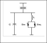
tained. It results, however, in the generation of odd harmonic current components during the control process.
Fig. 2. Thyristor-controlled capacitor
Full conduction is achieved with a gating angle of 90°. Par- tial conduction is obtained with gating angles between 90° and 180°, as shown in figure 2.5. By increasing the thyristor gating angle, the fundamental component of the current reac- tor is reduced [17]. This is equivalent to increase the induct- ance, reducing the reactive power absorbed by the reactor. However, it should be pointed out that the change in the reac- tor current may only take place at discrete points of time, which means that adjustments cannot be made more fre- quently than once per half-cycle. Static compensators of the TCR type are characterized by the ability to perform con- tinuous control, maximum delay of one half cycle and practi- cally no transients. The principal disadvantages of this con-
Fig. 3. Combined TSC and TCR configuration
In those cases where the system with switched capacitors is used, the reactive power is divided into a suitable number of steps and the variation will therefore take place stepwise [2]. Continuous control may be obtained with the addition of a thyristor-controlled reactor. When it is required to absorb re- active power, the entire capacitor bank is disconnected and the equalizing reactor becomes responsible for the absorption. By coordinating the control between the reactor and the capacitor steps, it is possible to obtain fully step less control. Static com- pensators of the combined TSC and TCR type are character- ized by a continuous control, practically no transients, low generation of harmonics (because the controlled reactor rat- ing is small compared to the total reactive power), and flexibility in control and operation. An obvious disadvantage of the TSC-TCR as compared with TCR and TSC type com- pensators is the higher cost. A static VAR system provides a fast, smooth and step-less variation of compensation of reac- tive power injected into the line. It ensures an accurate voltage control of buses over a wide range of loads.
The connected capacitor and inductor are switched on and off with frequent change of load which causes the system current either lagging or leading. The thyristor, triac, MOSFET, J-FET etc can be used as a switch because the turned on and turned off depends on gate pulse of that electronics devices [4, 13]. The major drawback of an SCR is that it can conduct in one direction only. Therefore, an SCR can only control dc power or forward biased half cycles of ac power in a load [19]. However, in an ac. system, it is of- ten desirable and necessary to control over both positive and negative half-cycles. For this purpose, triac can be used as a switching device which conducts during positive and negative half cycle of the voltage. Triac is widely used for controlling alternating current in a load since it has large
IJSER © 2012
International Journal of Scientific & Engineering Research, Volume 3, Issue 11, November-2012 4
ISSN 2229-5518
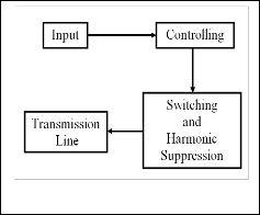
current handling capacity [15]. The Figure 4 shows the simple block diagram of the compensator which comprises of input, controlling, switching and harmonic suppression sections.
takes decision according to programming logic and thereby provides gate pulses to the switching device.
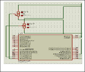
Fig. 4. Simple block diagram of compensator
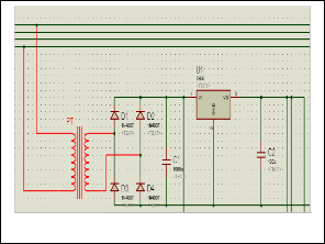
The input section comprises of a stepped down transform- er, bridge rectifier, IC7805 and capacitor which is shown in figure 5.
Fig. 6. Contolling Section
Fig. 5. Input Section
Fig. 7. Contolling Section
The high voltage of transmission system is stepped down to
12V ac by transformer. The output of the installed PT of the transmission system can be used for the input section. After
stepped down, the ac is converted to dc by rectifier and capac- itor is used for filtering the ripple content to provide pure dc voltage to the input of IC 7805. The IC 7805 is used for gener- ating constant 5V which is used as reference voltage for mi- crocontroller.
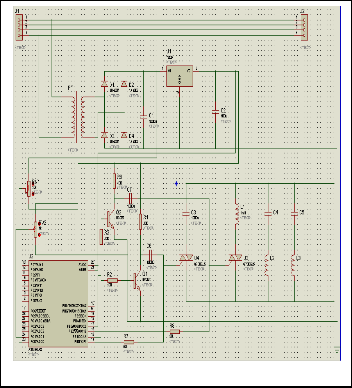
Figure 6 shows the controlling section which is designed with two variable resistors and microcontroller ATmega8. The variable resistor RVI is connected with the input of IC
7805 for taking the real time system voltage of transmission line. The real time system voltage acts as an input to the port ADC0 of ATmega8 microprocessor. The variable resis- tor RV2 is connected with the output of IC 7805 for getting the reference voltage which is fed as an input to the port ADC1 of ATmega8 microprocessor. The microprocessor
The figure 7 shows the switching section of the compensator. The switching section comprises with transistor and triac. When the transmission line voltage decreases with the incre- ment of inductive load, the microprocessor sends gate pulses to that triac which connects the capacitor with the transmis- sion line. On the other hand when the transmission line volt- age is increased for lightly load or no load condition, the mi- croprocessor sends gate signal to that triac which connects the inductor with the transmission line. But at the same time the triac needs to be turned off which already connects the capaci- tor with the transmission line. Since the microprocessor gener- ates only positive pulse, therefore the positive generated pulse is inverted by using common emitter (CE) transistor. The CE transistor provides a phase difference of 180 degree between the input and output voltage due to its phase reversal charac- teristics. Similarly when the capacitor is connected with the transmission line then the triac which already connects the inductor with the transmission line is turned off by using the negative pulse from the output of the CE transistor.
IJSER © 2012
International Journal of Scientific & Engineering Research, Volume 3, Issue 11, November-2012 5
ISSN 2229-5518
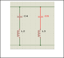
The effect of harmonics will create unbalance in the system due to rapid switching of the triac for connecting the capacitor and inductor with the transmission line according to system requirement. The figure 8 shows the harmonics suppresser of the compensator which comprises of capacitor and inductor connected in parallel with transmission line.
Fig. 8. Diagram fro harmonic suppression
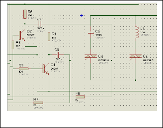
The figure 9 shows that the complete compensator circuit diagram. The input voltage is collected from the single phase line from three phase transmission system and it is stepped down by transformer to 12V ac.
microcontroller ATmega8 compares the real time system volt- age with the reference voltage which is collected from the out- put of 7805. The two variable resistors are connected with two inputs ADC0 and ADC1 of microcontroller for adjusting of real time system voltage and reference voltage respectively.
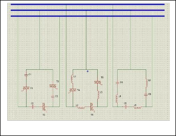
The real time system and reference voltages are connected with PC0/ADC0 and PC1/ADC1 input ports of the microcon- troller. When the ADC0<ADC1 due to the increment of lag- ging load in the transmission line, the output port PB0 pro- vides 5V to the gate of the triac U4 which connects the capaci- tor C3 with the transmission line. Again when the ADC0>ADC1 due to light load or no load in the transmission line, the output port PB2 provides 5V to the gate of thyristor U3 which connects the inductor L1 with the transmission line. At that same time the out port PB1 provides another 5V pulse to the base of Q1. The collector of Q1 transistor is connected with 5V. The NPN transistor Q1 which is in CE configuration inverts the input base signal by 180 degree out of phase to its output at collector. There is a capacitor C6 connected with col- lector of Q1 to block the dc component of the signal. After fil- tering the dc the -5V pulse is fed to the gate of triac U4 for turning it off by force commutation. Similarly when the capac- itor is on, the traic U3 is turned off by the negative gate pulse of the NPN transistor Q2 which is in CE configuration. The negative gate pulse is generated by transistor Q2 in a similar way of Q1 which inverts the 5v signal of the port PB3. The capacitor C7 is connected with the collector to block the dc component of the signal. After filtering the dc the -5V pulse is fed to the gate of thyristor U3 to turn it off by force commuta- tion. This process is repeated according to the change in sys- tem voltage. The designed reactive power compensator can be also used in the 3 phase system which is shown in the figure
10 where the inductor bank, capacitor bank and harmonic suppressor are connected in delta.
Fig. 9. Complete circuit diagram for compensator
The microcontroller does not work with ac voltage that’s why it is needed to convert the dc by the full wave bridge rec- tifier. Although the rectifier converts ac to pulsating dc having ripples. In order to discord the ripples, the capacitor C1 is used. The IC 7805 is used to get constant 5V which is used as supply voltage for microcontroller as well as reference voltage for ADC of microcontroller. The capacitor C2 is used for avoid any kind of ripple in input voltage of microcontroller. The
Fig. 10. Design of 3 phase compensator
This section The Proteus software is used for obtaining the simulation results of the designed compensator. The figure
11 shows the simulated output of the gate pulse for turning
IJSER © 2012
International Journal of Scientific & Engineering Research, Volume 3, Issue 11, November-2012 6
ISSN 2229-5518
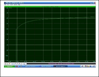
on the triac U4 in order to connect the capacitor C3 with the transmission line when the real time system voltage is less than the reference voltage. Whereas the figure 12 shows the simulated output of the gate pulse for turning on the triac U3 in order to connect the capacitor L1 with the transmis- sion line when the real time system voltage is greater than the reference voltage.
The figure 14 shows the simulated result of the system voltage before and after reactive power compensation when the system voltage is decreased from the rated value of the transmission line. Similarly the figure 15 shows the simulated result of the system voltage before and after reactive power compensation when the system voltage is increased from the rated value of the transmission line. In both figures the red and yellow wave shapes indicate the system voltage before and after compensation respectively. It is seen that the un- compensated voltage wave lags the compensated voltage wave by 30 degree after connecting the capacitor C3 with the transmission line which is shown in figure 14 whereas the un- compensated voltage wave leads the compensated voltage wave by 30 degree after connecting inductor L1 with the transmission line which is shown in figure 15.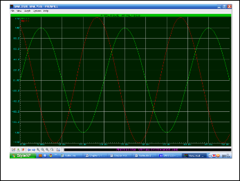
Fig. 11. Gate pulse to turn on the triac U4
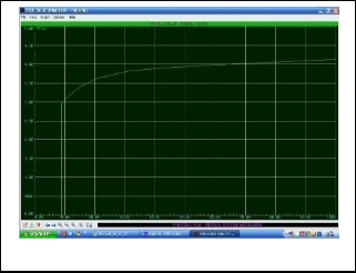
Fig. 14. Reactive Power Compensation after capacitor is connected
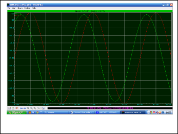
Fig. 12. Gate pulse to turn on the triac U3
The figure 13 shows the simulated result of negative gate pulse generated by the transistor Q1 to turn off the triac U4.
Fig. 15. Reactive Power Compensation after inductor is connected
Fig. 13. Negative pulse to turn off the triac U4
Although a Variation of system voltage and frequency with variation of load is a very common problem in electrical pow- er system. In order to ensure quality power to consumers it is
IJSER © 2012
International Journal of Scientific & Engineering Research, Volume 3, Issue 11, November-2012 7
ISSN 2229-5518
necessary to maintain system voltage and frequency at rated value according to the designed system. The real and reactive power also needs to be at rate value according to the designed system. The system reliability can be maintained by compen- sating the reactive power to a certain level. The static VAR compensator is used for reactive power compensation for high voltage transmission system. The combination of TSC and TCR are commonly usable method for reactive power com- pensation. The designed prototype microcontroller based compensator is the combination of TSC and TCR with har- monics suppressor. Though it is designed for single phase sys- tem but it can be implemented for three phase system as well. The reactive power compensator can be used for both HVDC and HVAC system. The concept of FACTS for EHV system arises in order to ensure reliability with minimum supervision by using advanced technology. The SVC pulse which is de- signed by SIMENS is an example of utilization of semiconduc- tor devices like thyristor for faster switching of connecting capacitor and inductor bank with the transmission according to the system requirement without interference of harmonics due to switching. The proposed design reactive power com- pensator having triac and microcontroller provides a new con- cept for reactive compensation of EHV/UHV (Extra High Voltage /Ultra High Voltage) system.
[1] John J. Grainger, William D. Stevenson, “Power System Analysis,” Tata
Mcgraw Hill 2003, New Delhi, India
[2] Ashfaq Husain.”Electrical Power Systems,”Fifth Edition, 2007, CBS Publisher, New Delhi
[3] V.K. Mehta and Rohit Mehta.”Principles of Power Systems,”Fourth
Revised Edition 2011, S. CHAND, New Delhi, India
[4] Hadi Sssdat. “Power System Analysis,” Revised Edition, 1999, Tata
McGraw-Hill Publishing Company Limited. New Delhi, India
[5] J. Duncan Glover, Mulukutla S. Sarma and Thomas J. Overbye. “Power Sys- tem Analysis and Design,” Fourth Edition 2008, Thomas Learning, On- tario, Canada
[6] Debapriya Das. “Electrical Power Systems,” 2006, New Age International
(P) Ltd., Publishers, New Delhi, India
[7] Sunil S. Rao. “Switchgear Protection and Power Systems,”Twelveth
Edition, Khanna Publishers, New Delhi, India
[8] Ed. Richard C. Dorf.” The Electrical Engineering Handbook,”2000, CRC Press LLC, USA
[9] L. Gyugyi, R. Otto, T. Putman, “Principles and Applications of
Static, Thyristor-Controlled Shunt Compensators,” IEEE Transaction on PAS, vol. PAS-97, nº 5, pp. 1935-1945, Oct. 1980
[10] C. Edwards, K. Mattern, E. Stacey, P. Nannery, J. Gubernick, “Ad- vanced Static VAR Generator Employing GTO Thyristors,” IEEE Transaction on Power Delivery, vol. 3, nº 4, pp. 1622-1627, October 1988
[11] Karl E. Stahlkopf and Mark R. Wilhelm, “Tighter Controls for Busier
Systems,” IEEE Spectrum, Vol. 34, N° 4, April 1997, pp. 48-52
[12] Muhammad H. Rashid. “Power Electronics Handbook,” 2001, Har- court Science and Technology Company, USA
[13] SCR’s and Triacs in Automotive Applications, 2004, STMicroelec-
tronics Group of Companies, USA
[14] Thyristor Theory and Design Considerations. ON Semiconductor,
2005, USA
[15] B.L. Theraja and A.K. Theraja. “Electrial Technology,” Volume IV, Revised Twenty Third Edition, 2002, S.CHAND, New Delhi. India.
[16] Robert RBoylestad,“Introductory Circuit Analysis,”Eleventh Edition,
Pearson Education, Inc, USA
[17] Juan Dixon, Luis Morán, José Rodríguez and Ricardo Domke, “Reac- tive Power Compensation Technologies, State-of-the-Art Review,” IEEE Transaction on Industry Applications, vol. IA-25, nº 4, pp. 598-
608, July/August 1989
IJSER © 2012