
International Journal of Scientific & Engineering Research, Volume 6, Issue 3, March-2015 1572
ISSN 2229-5518
Design and performance issues of Microstrip
Antennas
Vinay bankey, N. Anvesh Kumar
Abstract—In recent years, microstrip antennas are playing an important role in wireless communication systems because of their many advantages like light weight, low profile, low cost, easy integration with planar structure and easy fabrication. So, it is very much essential to know all the aspects of microstrip antennas. The main objective of this paper is to discuss the design and performance issues of microstrip antennas. The design issues include microstrip antenna dimensions, feeding techniques and various polarization mechanisms whereas the performance issues include gain enhancement, bandwidth issues and reconfigurable microstrip antennas. This paper is also aimed to introduce few applications of microstrip antennas like W i-Fi, W i-MAX, RF energy harvesting, Cognitive radio, GSM, Radar and ultra-wide band. Microstrip antennas are also having disadvantages like low gain and low efficieny.
Index Terms—active patch,cognitive radio,feeding techniques, gain enhancement, impedance bandwidth, polarization, reconfigurable patch, ultra-wide bands.
————————————————————
N Antenna is a sensor and transducer that converts elec- trical signals into electromagnetic waves and electro- magnetic waves into electrical signals. In modern wire-
less communication systems an antenna with low cost, small size, easy fabrication with good performance is required. For those systems microstrip antennas are the best because of their enormous advantages. Microstrip antennas also known as patch antennas. This paper completely explains the design and performance issues of patch antennas along with their applica- tions. In this paper, initially we focus on the design and per- formance issues of microstrip antennas.
In this section, we present the design issues of microstrip an- tennas. As discussed earlier, the design issues include antenna dimensions, feeding techniques and various polarization mechanisms. Here, we present the dimensions of a patch an- tenna.
Basic patch antenna consists of two good conducting layers separated by a dielectric substrate of thickness (h) as shown in Fig 1. Upper conducting layer is known as radiating patch or active patch whereas the bottom layer is referred as ground patch. The good conducting material may be copper, gold or aluminium. The active patch may take various shapes like square, rectangular, circular, elliptical or triangular. Different shapes are having different advantages, but most of the times circular and rectangularactive patches are preferred [1]. Gen- erally, the microstrip antenna dimensions are expressed in terms of mathematical equations. Dimensions of an active
————————————————
• Vinay bankey is with Electronics and Communications Engineering De- partment, VNIT Nagpur-440010, India as M.Tech Scholar, (phone:
8149219260; E-mail: vinaybankey@gmail.com).
• Nella Anvesh Kumar is with Electronics and Communications Engineering
Department, VNIT Nagpur-440010, India as Research Scholar, (phone:
9503132874; E-mail: nellanavesh@gmail.com).
patch play a vital role on antenna performance. Here, we focus on the dimensions of a rectangular active patch [2-5].
Fig 1: Basic rectangular microstrip antenna.
Basic rectangular active patch is having length (L), width (W) and thickness (t) as shown in Fig 1. Standard thickness of the active patch is 0.35µm. However, it may be a different val- ue, but must be as small as when compared with the free
space wavelength (𝜆𝑜 ). i.e. t << 𝜆𝑜 .
Width (W) of the radiating patch is given by the equation
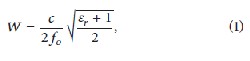
(1).
Where, 𝑓𝑜 is the resonant frequency, 𝜀𝑟 is the dielectric con- stant or relative permittivity and c is the velocity of light in
free space.
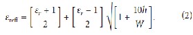
Effective permittivity or effective dielectric constant of the
dielectric substrate when W/h > 1, is given by the equation (2).
Length of the active patch (L), which is more responsible
for better antenna performance generally lies between 𝜆𝑜 ⁄3
IJSER © 2015 http://www.ijser.org
International Journal of Scientific & Engineering Research, Volume 6, Issue 3, March-2015 1573
ISSN 2229-5518![]()
and 𝜆𝑜⁄2. However, it is given by the equation (3).
![]()
Where, Δl or ΔL is the extended line length on both sides of the active patch due to the effect of fringing fields [6].
To obtain the dimensions of a rectangular active patch very quickly a link given in [7] can also be followed. In this link, dimensions of the active patch can be achieved by substituting
the known values like 𝜀𝑟 , h and resonant frequency (𝑓𝑜 ). Once
we got the dimensions of an active patch it is possible to calcu-
late the width (Ws) and lengths (Ls) of the dielectric substrate by using equations (5) and (6). Here, ‘W’ and ‘L’ are width and lengths of the active patch respectively.
Ws=W+6h (5)
Ls=L+6h (6)

However, antennas may also resonate at same frequencies with dimensions which are not matching with these calcula- tions. But, the antennas resonate exactly at the particular oper- ating frequency with these calculations. Basically, microstrip antennas primarily radiate by the virtue of fringing fields be- tween the patch edge and the ground plane as shown in Fig 2.
Fig 2: Fringing fields in patch antenna [8].
To have better performance in terms of radiation or band-
width, we need a dielectric substrate with low dielectric con-
stant (𝜀𝑟 ) and more thickness (h). Generally, the value of 𝜀𝑟
lies between 2.2 to 12.
i.e. 2.2 ≤ 𝜀𝑟 ≤ 12.
If the value of 𝜀𝑟 is small, then we get good radiation from
the antenna. If it is high, then the fields are more tightly con-
tained in the substrate which results in less radiation. The die-
lectric substrate with high 𝜀𝑟 is desirable in microwave circuit-
ry to minimize undesired radiation and coupling [9].As dis-
cussed earlier, the value of substrate thickness (h) must be as
high as possible to obtain high efficiency and high bandwidth. But, if we increase the height of substrateit may degrade an- tenna pattern and polarization characteristics. The value of
substrate thickness is like 0.003𝜆𝑜 ≤ h ≤ 0.05𝜆𝑜 [10].
Ground patch is with good conducting material takes the dimensions of the dielectric substrate. However, it may be partial or full ground with slots according to the requirement.
The patch antennas are having disadvantages like low effi- ciency, low power handling capacity, high Q-factor, poor po- larization purity, poor scan performance, spurious feed radia- tion and very narrow bandwidth.
In the design of microstrip antennas, it is necessary to connect the active patch with ground patch by using various tech- niques. These techniques are called feeding techniques. In fact, the scheme of feeding technique also plays an important role on antenna performance. There are various feeding techniques applied to the patch antennas. The most popular feeding tech- niques [11, 12] are microstrip line [13, 14], coaxial probe [5], aperture coupling and proximity coupling.
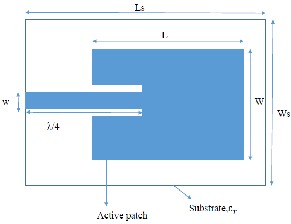
Among the above feeding techniques microstrip line feed- ing is very simple and easy for fabrication [10]. There are dif- ferent microstrip line feeding techniques presented in [14], out of them the microstrip line with inset feeding shown in Fig 3 is widely used. The main advantage of using this mechanism is that, impedance matching can be done easily by adjusting the position of inset feed [1, 13]. According to the standard rela- tions discussed in [1], dimensions of the microstrip line width and length can be understand by the links mentioned in [15]. In the first link of [15], ‘w’ and λ/4 are the width and the lengths of microstrip line for proper impedance matching.
Fig 3: Microstrip antenna with inset feeding.
Basically, the microstrip line with inset feeding introduces a physical notch which causes a junction capacitance. The capac- itance and the notch influence the resonant frequency by 1%.
Polarization is defined as the propagation or orientation of the electric flux lines in an electromagnetic field. Basically, elec- tromagnetic waves propagate in three different polarizations. They are linear, circular and elliptical polarizations [16]. By applying conventional feedings to the rectangular and circular patches we can obtain linear polarization [17, 18]. A linearly polarized patch antenna with co-axial feeding is shown in Fig
4.
IJSER © 2015 http://www.ijser.org
International Journal of Scientific & Engineering Research, Volume 6, Issue 3, March-2015 1574
ISSN 2229-5518
Fig 4: Proposed linearly polarized patch antenna with Co-axial feed [17].
We can obtain circular and elliptical polarizations by modi- fying the designs or by using different feedings. Generally, circular polarization to an antenna can be achieved when two orthogonal modes are excited with a phase difference of 90 degrees. It can be done by adjusting the dimensions of the patch with single or two [1, 19] or more feeds. Phase difference of 90 degrees is obtained by using 90 degree power dividers or hybrids as shown in Fig 5.
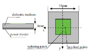
Fig 5: Circularly polarized patch antenna with two feedings [19].
Sometimes, slits on the active patch with single feed also plays an important role in obtaining circular polarization [20-
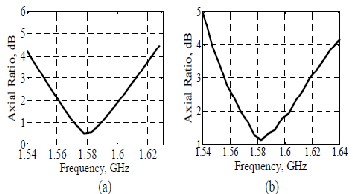
23]. In some situations normal antenna designs can also yield circular polarization [24].
Fig 6: Measured axial ratios of proposed circular polarized antennas [20].
Microstrip antenna model for an elliptical polarization is discussed in [25]. In software simulations, there is one parame- ter called axial ratio through which the type of polarization is identified. Axial ratio is the ratio of orthogonal components of an electric field. The axial ratio is unity (0 dB) for circular po- larization, because the orthogonal components are equal in magnitude and having a phase difference of ±90 degrees. The axial ratio for an elliptical polarization is larger than 1 (> 0 dB). For a perfect linear polarization the axial ratio is infinite [26].
As mentioned above, the performance issues include gain en- hancement, bandwidth issues and reconfigurable patch anten- nas. Initially, we present the issues related to the gain en- hancement.
Enhancing the gain of a microstrip antenna is a complex job. However, it can be increased to some level by introducing dif- ferent designs.

First one is, by introducing multilayer substrates in the de- sign of a patch antenna as shown in Fig 7 [27, 28]. In this method, we need to use different dielectric materials with dif- ferent or similar heights. Air can also be used as a dielectric substrate.
Fig 7: Two level substrate microstrip antenna.
Second one is, by integrating electromagnetic band gap (EBG) structures [29-31] within the microstrip antennas [32]. By using EBG structures in the patch antenna, we can reduce surface wave effects. The reduction in surface wave effects result in the improvement of the gain. Combination of slots and with or without the integration of EBG structures can also be used for enhancing the gain [33]. EBG designs are also used to enhance efficiency [34].
Third one is, by the proper selection of substrate relative permittivity and thickness [35, 36]. We need a substrate with low relative permittivity and small thickness for achieving improved gain.
There are various bandwidths related to the antenna perfor- mance. They are impedance or return loss bandwidth, di- rectivity bandwidth, gain bandwidth, efficiency bandwidth, polarization bandwidth and axial ratio bandwidth. Most of the times we consider impedance bandwidth of a patch antenna.
The main disadvantage of a patch antenna is narrow band- width. However, in terms of impedance bandwidth we can obtain bandwidth in Giga hertz ranges. By using patch anten- nas we can achieve very narrow bands [23, 37] as well as ultra- wide bands [38-40]. There are some key points to obtain ultra- wide bands [41]. Round edges and round shapes lead to smoother current flow, which results to ultra-wide band char- acteristics [42-44]. Partial ground planes and full ground planes with specially designed slots play a key role in obtain- ing UWB behavior [45, 46]. However, we can obtain ultra-wide band characteristics without round shapes and partial grounds [47-50], but the above key points give success to ob- tain wide bands. In recent years, UWB applications are becom- ing very popular because of high data rate over short distanc-
IJSER © 2015 http://www.ijser.org
International Journal of Scientific & Engineering Research, Volume 6, Issue 3, March-2015 1575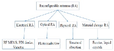
ISSN 2229-5518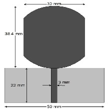
es, low power consumption, high secure and high reliable communication solutions.
Fig 8: Proposed UW B antenna [38].
Basically, the UWB range approved by FCC in 2002 (3.1GHz to 10.6GHz) covers the frequencies of Wi-Fi as well as Wi- MAX bands. While designing patch antennas if we want to avoid interference between these bands and UWB bands, we need to design UWB antennas with band notch characteristics. To perform band rejection function we need to introduce some specially designed slots onto the active patch. These slots can act as band notched or band rejection functions. The dimen- sions of the slots or strips depend upon the rejection bands which we want to reject [51, 52]. At the desired frequency, the length of the strip is about half or quarter of the guided wave- length.
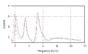
Fig 9: VSW R vs. frequency plot of the proposed UW B antenna with rejec- tion bands [51].
In modern wireless communication systems, an antenna with variable characteristics is required. For those applications re- configurable antennas are having huge demand. Patch anten- nas can be designed as reconfigurable in which the perfor- mance characteristics of the designed antenna will change ac- cording to the reconfiguration of the design. There are basical- ly four types of reconfigurable antennas [53] as shown in Fig
10. The performance characteristics may be frequency or ra- diation or polarization or any combination of this. Due to the reconfiguration, if resonant frequency is changing then the concerned antenna is known as frequency reconfigurable an- tenna. Similarly, if polarization is changing, then the antenna is known as polarization reconfigurable antenna.
Fig 10: Types of reconfigurable antennas [53].
There are many ways to reconfigure the design. Some of them are done by introducing switches like PIN diodes [54-
56], varactor diodes [57], RF-MEMS switches [58] or by alter- ing the structure of the design [59] or by using materials like ferrites or liquid crystals as substrate material. Another way of doing reconfiguration is by introducing switches of photocon- ductive elements [60].

Fig 11: Proposed reconfigurable microstrip antenna with PIN diodes [54].
In case of electrical reconfigurable antennas, reconfigurabil- ity is achieved by making switches ON and OFF [61]. Similar- ly, in case of optical reconfigurable antennas, the photocon- ductive switches made ON and OFF by exposing them to a laser light of proper wavelength. In physical or structural re- configurable antennas, the physical structure of the active patch changes according to the requirement of performance characteristics. In material change reconfigurable antennas case, dielectric substrates are fabricated by using smart mate- rials like ferrites or liquid crystals. The advantage of using these materials is that, the substrate relative permittivity and permeability can be varied by various methods. Once the sub- strate properties are varying means reconfigurability is achieved.
The main advantages of the reconfigurable antennas are fast tuning, low cost, time and space saving. However, they are having disadvantages like power consumption, non-linear effects of switches, interference and losses. Moreover, these antennas require biasing networks for activation or deactiva- tion of the switching elements which makes antenna design complex.
Patch antennas can also be designed in folded models so that they are useful in structures like flexible electronic sys- tems [62].
IJSER © 2015 http://www.ijser.org
International Journal of Scientific & Engineering Research, Volume 6, Issue 3, March-2015 1576
ISSN 2229-5518
In this section, we discuss various applications and softwares used for microstrip antennas.
Because of enormous advantages of patch antennas, they are widely used in many applications like Laptops, mobiles (for GSM [63-65], Wi-Fi [66, 67], GPS [68], Bluetooth [69] and Wi- MAX [70, 71]), ultra-wide Band [38-52], Satellite communica- tion, RF energy harvesting [72-75], MIMO, Cognitive radio [76-78], Radio frequency identification (RFID)[79], radar, body centric communication and so on.
We can model microstrip antenna designs for single as well as multiband operations. For example, we can design a mi- crostrip antenna for Wi-Fi application as wellas for Wi-Fi, Wi- MAX and GSM (multi bands) applications as shown in Figures
12 and 13.
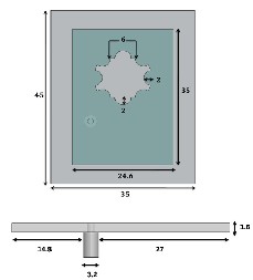
Fig 12: Proposed antenna for GSM, W i-Fi and W i-MAX applications [71].
All over the world, Wi-Fi applications cover two frequency bands. First one is 2.4GHz band (2.401GHz-2.484GHz) [80] and second one is 5GHz band [81]. There are almost five bands for Wi-MAX applications. Those are 2.3GHz, 2.5GHz,
3.3GHz, 3.5GHz and 5.8GHz bands [82, 83].
Fig 13: Simulated and measured return loss of proposed GSM, W i-Fi and
Wi-MAX antenna [71].
Main idea of RF energy harvesting is to save RF energy from radio environment. The harvested energy can be used for
small voltage electronic devices. Initially, to sense the RF ener- gy from the radio environment we need antennas like patches with ultra-wide band characteristics. However, narrow band antennas can also be used, but it depends upon the frequency bands which we are going to sense. For example, to sense GSM 900 frequencies we need an antenna with narrow band characteristics.
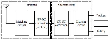
Fig 14: System of RF energy harvesting for electronic devices [74].
In order to enhance the performance characteristics of wire- less communication systems multiple input multiple output systems are employed. The MIMO systems uses multiple an- tennas at transmitting and receiving ends to increase the sys- tem coverage, QoS, capacity, and spectral efficiency. Because of their enormous advantages, microstrip antennas are widely used in MIMO applications.
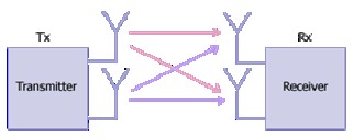
Fig 15: MIMO system.
Cognitive radio is a radio in which the licensed spectrum (utilized by primary user) is utilized by unlicensed user (sec- ondary user) when the channel is free. In this application, we need an UWB antenna to detect or to sense the spectrum hole (free channel) and another reconfigurable NB antenna for communication as shown in Fig 16.
Fig 16: Working flow of Cognitive radio system [84].
However, it is possible to integrate UWB and NB antennas
IJSER © 2015 http://www.ijser.org
International Journal of Scientific & Engineering Research, Volume 6, Issue 3, March-2015 1577
ISSN 2229-5518
into one antenna so that it is useful for spectrum sensing as well as for communication [85-87]. The integrated UWB and NB antennas are designed in such a way that the mutual cou- pling between them must be as low as possible.
Fig 17: Proposed dual port Integrated UW B and reconfigurable NB anten- na for cognitive radio (a) Top view (b) Bottom view [85].
For UWB as well as NB applications microstrip antennas
are extensively used because of their wide advantages.
• HFSS.
• FEKO.
• ADS.
• AWR.
• IE3D.
• CST- Microwave studio.
• Antenna Magus.
• AN-SOF.
• 4NEC2.
• MATLAB.
Nowadays, reconfigurable antennas are dominating be- cause of their huge advantages. But, they also require addi- tional hardware for activation and deactivation of switch- es.Sometimes, they need different voltage levels. In future, multiport antennas may play an important role because they support multiband and multiple applications. If we are able to achieve better isolation between the ports, then multiport an- tennas become the best solution for space, time and cost.
In this paper, we focus on the basic and important concepts of microstrip antennas. This paper also presents the gain en- hancement techniques and reconfigurable antenna types. We also discuss the current research applications of microstrip antennas. Finally, we can say that this paper covers all the as- pects of microstrip antennas.
[1] Constantine A. Balanis “A Book on Antenna Theory: Analysis and
Design (Third edition)”.
[2] Rachmansyah, Antonius Irianto, and A. Benny Mutiara, “Designing and manufacturing Microstrip antenna for wireless communication at 2.4GHz”, International Journal of Computer and Electrical Engineering, Vol. 3, No. 5, October 2011.
[3] Preet Kaur, Rajiv Nehra, Manjeet Kadian, Dr. Asok De, Dr.
S.K.Aggarwal, “Design Of Improved Performance Rectangular
Microstrip Patch Antenna Using Peacock And Star Shaped DGS”,
International Journal Of Electronics Signals And Systems (Ijess), Issn:
2231- 5969, Vol-3, Iss-2, 2013.
[4] Lalitha Koyya, Dr.Rajya Lakshmi Valluri, Dr.GSN Raju, “Optimization of Geometry of Microstrip patch antenna for Broadband applications”, International Journal of advance Research in Electrical, Electronics and Instrumentation Engineering Vol. 2, Issue7, July 2013.
[5] Alak Majumder, “Rectangular Microstrip patch Antenna Using Coaxial Probe Feeding Technique to operate in S-Band”, International Journal of Engineering Trends and Technology (IJETT)
– Volume 4, Issue 4, April 2013.
[6] M. Habib Ullah, M. T. Islam, M. R. Ahsan, J. S. Mandeep, and N.Misran, “A Dual Band Slotted Patch Antenna on Dielctric Material Substrate”, Hindawi Publishing Corporation, International Journal of Antennas and Propagation, Volume 2014, Article ID 258682, 7 pages.
[7] Patch dimension calculator.
http://www.everythingrf.com/rf-calculators/microstrip-patch- antenna-calculator.
[8] Fringing fields in patch antenna. http://fab.cba.mit.edu/classes/MIT/862.06/students/alki/GA.html.
[9] Effect of substrate dielectric constsant on radiation.
http://www.antenna-theory.com/antennas/patches/antenna.php. [10] Project thesis: A thesis on microstrip patch antenna.
http://ethesis.nitrkl.ac.in/1748/1/project_thesis.pdf.
[11] Marek Bugaj, Rafal Przesmycki, Leszek Nowosielski, and Kazimierz Piwowarczyk, “Analysis Different Methods of Microstrip Antennas feeding for their Electrical Parameters”, PIERS Proceedings, Kuala Lumpur, Malaysia, March 27-30, 2012.
[12] K. Praveen Kumar, K. Sanjeeva Rao, T. Sumanth, N. Mohana Rao, R.
Anil Kumar, Y.Harish, “Effect of Feeding Techniques on the
radiation Chaaracteristics of Patch antenna: Design and Analysis”,
International Journal of Advanced Research in computer and
communication Engineering Vol. 2, Issue 2, February 2013.
[13] Prof. Mahesh M. Gadag, Mr. Dundesh S. Kamshetty, Mr. Suresh L.
Yogi, “Design of Different Feeding techniques of rectangular
Microstrip Antenna for 2.4GHz RFID Applocations Using IE3D”,
Proc. of the Intl. Conf. on Advances in Computer, Electronics and
Electrical Engineering, ISBN: 978-981-07-1847-3, doi:10.3850/978-981-
07-1847-3 P1036.
[14] Dalia M. Elsheakh, Esmat A. Abdallah, “Different Feeding Techniques of Microstrip Patch Antennas with Spiral Defected Ground Structure for Size reduction and Ultra-Wide band Operation”, Journal of Electromagnetic Analysis and Applications,
2012, 4, 410-418..
[15] Microstrip line length and width calculator: http://www1.sphere.ne.jp/i-lab/ilab/tool/ms_line_e.htm. http://images.elektroda.net/100_1253249028.gif.
[16] Polarization concept:
http://www.antenna-theory.com/basics/polarization.php.
[17] Tazeen Shaikh and Rukhsana Khan, “Design of Compact Linearly Polarized Microstrip Patch antenna for Wireless Communication”, International Journal of Information and Education Technology, Vol.
2, No. 5, October 2012.
[18] Mi-ra Ryu, Jong-Myung Woo, Jung Hur, “Skimmer-shaped Linear Polarized Circular Microstrip Antennas for Miniaturization”, ISBN,89-5519–129–4–755-Feb.20-22, 2006, ICA0T2006.
IJSER © 2015 http://www.ijser.org
International Journal of Scientific & Engineering Research, Volume 6, Issue 3, March-2015 1578
ISSN 2229-5518
[19] Yun Xue XU, Shu Xi Gong, Ying Guan, “Design of a Double
Microstrip Patch antenna on a circular asymmetrical carrier”, 978-1-
4673-2185-3/12/$31.00 ©2012 IEEE.
[20] Muhammad Fahad Farooqui, and Atif Shamim, “ Inkjet Printed
Circularly Polarized antennas for GPS Applications”, 978-1-4799-
3540-6/14/$31.00 ©2014 IEEE 856 AP-S 2014.
[21] Tomoya Ijiguchi, Daisuke Kanemoto, Kuniaki Yoshitomi, Keiji Yoshida, Akira Ishikawa, Shugo Fukagawa, Noriyuki Kodama, Akihiro Tahira, and Haruichi Kanaya, “Circularly Polarized One- sided Directional Slot Antenna with Reflector Metal for 5.8-GHz DSRC Operations”, IEEE Antennas And Wireless Propagation Letters, Vol. 13, 2014.
[22] K. Fujita, D. Kanemoto, K. Yoshitomi, K. Yoshida, and H. Kanaya, “UWB Circularly Polarized Planar Antenna on Flexible Substrate”,
2013 IEEE MTT-S International Microwave Workshop Series on RF
and Wireless Technologies for Biomedical and Healthcare
Applications (IMWS-BIO), 978-1-4673-6096-8/13/$31.00 ©2013 IEEE.
[23] M.Z.A. Abd. Aziz, N.A.A. Mufit, M.K. Suaidi, M.A. Othman, M.F.
Johar, N. Hassan, M.K.A. Rahim, “Investigation of Single Stub on
Circular Polarized Patch Antenna At 2.4GHz”, 978-1-4673-5517-9
©2013 IEEE.
[24] Prathiba Sekra, Sumita shekhawat, manoj Dubey, D. Bhatnagar, V. K.
Saxena And J. S. Saini, “Design of circularly Polarized edge truncated
elliptical patch antenna with improved performance”, Indian Journal
of Radio & Space Physics, Vol 40, August 2011, pp 227-233.
[25] V. Priyashman, M. F. Jamlos, H. Lago, M. Jusoh, Z. A. Ahmad, M. A.
Romli, M. N. Salimi, “Elliptical Shape Microstrip Patch antenna
without Dots”, 978-1-4673-2210-2/12/$31.00 ©2012 IEEE.
[26] Definition of Axial ratio:
http://www.antenna-theory.com/definitions/axial.php.
[27] Kharade A.R., Patil V.P., “Enhancement of Gain of rectangular Microstrip antenna Using Multilayer Multidielctric Structure”, IOSR Journal of Electronics and Communication Engineering (IOSRJECE), ISSN : 2278-2834 Volume 2, Issue 6 (Sep-Oct 2012), PP 35-40.
[28] Neeraj Rao and V. Dinesh Kumar, “Gain and Bandwidth Enhancement of a MicrostripAntenna Using Partial Substrate Removal in Multiple-layer Dielectric Substrate”, Progress In Electromagnetics Research Symposium Proceedings, Suzhou, China, Sept. 12-16, 2011.
[29] Jun Kamiya, Kenichi Shirota, Takahiro Yagi, Tetsuo Nakazawa, “Study of EBG Structures Using Metamaterial Technology”, OKI Technical Review, April 2012 / Issue 219 Vol. 79, No.1.
[30] Alka Verma, “EBG structure and its recent advances in Microwave antenna”, International Journal of Scientific Research Engineering & Technology (IJSRET) , Volume 1, Issue 5 , pp 084-090, August 2012, www.ijsret.org , ISSN 2278 – 0882.
[31] Fan Yang, and Yahya Rahmat-Samii, “Microstrip Antennas Integrated with Electromagnetic Band Gap (EBG) Structures : A Low Mutual Coupling Design for Array Applications”, IEEE TRANSACTIONS ON ANTENNAS AND PROPAGATION, VOL. 51, NO. 10, OCTOBER 2003.
[32] Halim Boutayeb, and Tayeb A. Denidni, “Gain Enhancement of a Microstrip Patch antenna using a Cylindrical Electromagnetic Crystal Substrate”, IEEE Transactions On Antennas And Propagation.
[33] R. Dhanalakshmi, Santhosh Kumar, R. Srinivas, “Gain Enhancement of Slotted Microstrip Patch antenna using EBG”, The International Journal of Engineering And Science (IJES), || Volume || 3 || Issue
|| 6 || Pages || 53-57 || 2014 || , ISSN (e): 2319 – 1813 ISSN (p):
2319 – 1805.
[34] Z. Duan, D. Linton, W. Scanlon, G. Conway, “Using EBG to improve antenna Efficiency in Proximity to the Human Body”.
[35] Sohaib Abbas Zaidi and M.R. Tripathy, “Design and simulation Based study of Microstrip E-shaped Patch Antenna Using Different substrate Materials”, Advance in Electronic and Electric Engineering, ISSN 2231-1297, Volume 4, Number 6 (2014), pp. 611-616.
[36] Jorge Sosa-Pedroza, Sergio Peña Ruiz, and FabiolaMartínez-Zúñiga, “A 2.4GHz Cross Rhombic Antenna for A cube Satellite Application”, International Journal of Antennas and Propagation, Volume 2014, Article ID 268151, 10 pages.
[37] I. Balakrishna, M. Suresh kumar, S. Raghavan, “CPW-fed Semi Circle
Patch Antenna for 2.4GHz WLAN Applications”, 978-1-4577-0240-
2/11/$26.00 ©2011 IEEE.
[38] Mohammed Al-Husseini, Ali El-Hajj, and Karim Y. Kabalan, “A 1.9-
13.5 Low-Cost Microstrip Antenna”, 978-1-4244-2202-9/08/$25.00 ©
2008 IEEE.
[39] Sherif R. Zahran, Omar H. El Sayed Ahmed, Ahmed T. El-Shalakany, Sherif Saleh, Mahmoud A. Abdalla, “B10. Ultra Wode Band Antenna with Enhancement Efficieency For High Speed Communications”,
978-1-4799-3821-6/14/$31.00 ©2014 IEEE..
[40] Hui Zhao, Fushun Zhang, Chunyang Wang, and Jiangang Liang, “A Compact UWB Diversity Antenna”, Hindawi Publishing Corporation, International Journal of Antennas and Propagation, Volume 2014, Article ID 805853, 6 pages.
[41] Lise Safatly, Mario Bkassiny, Mohammed Al-Husseini, and Ali El- Hajj, “Cognitive Radio Tranceivers: RF, Spectrum Sensing, and Learning algoritums Review”, Hindawi Publishing Corporation, International Journal of Antennas and Propagation, Volume 2014, Article ID 548473, 21 pages.
[42] Anil Kamma, G. Shrikanth Reddy, Rajesh singh Parmar and Jayanta
Mukherjee, “Reconfigurable Dual-Band Notch UWB Antenna”, 978-
1-4799-2361-8/14/$31.00 ©2014 IEEE.
[43] Mohammed Al-Husseini, Youssef Tawk, Ali El-Hajj, and Karim Y.
Kabalan, “A Low-Cost Microstrip Antenna for 3G/WLAN/WiMAX
and UWB Applications”, 978-1-4244-3834-1/09/$25.00 © 2009 IEEE.
[44] Mohammed al-husseini, Ali ramadan, Youssef tawk, ali el-hajj, karim y. kabalan, “Design and ground plane optimization of a CPW-fed Ultra-Wideband Antenna”, Turk J Elec Eng & Comp Sci, Vol.19, No.2, 2011, ©TUBITAK, doi:10.3906/elk-1001-360.
[45] Basil K Jeemon, Shambavi K., Zachariah C Alex, “Design and
Analysis of a Multi-fractal Antenna for UWB Application”, 978-1-
4673-5036-5/13/$31.00 © 2013 IEEE.
[46] Chirag Gupta, Divyanshu Maheshwari, Ritesh Kumar Saraswat, Mithiles Kumar, “A UWB Frequency-Band Reconfigurable Antenna Using Switchable Slotted Ground Structure”, 978 – 1 – 4799 – 3070 – 8
/ 14 $31.00 © 2014 IEEE, DOI 10. 1109 / CSNT. 2014. 13.
[47] Vivek Kumar, Bharat Gupta, “Swastika Slot UWB Antenna for Body- worn Application in WBAN”, ISMICT 2014 1569883139.
[48] Purna B. Samal, Ping Jack Sohand Guy A. E. Vandenbosch, “UWB All-Textile Antenna With Full Ground Plane for Off-Body WBAN Communications”, IEEE Transactions On Antennas And Propagation, Vol. 62, No. 1, January 2014.
[49] Shuai Zhang, Zhinong Ying, Jiang Xiong and Sailing He, “Ultrawideband MIMO/Diversity Antennas With a Tree-Like Structure to Enhance Wideband Isolation”, IEEE Antennas And Wireless Propagation Letters, Vol. 8, 2009.
[50] Z. N. Low, J. H. Cheong, and C. L. Law, “Low-Cost PCB Antenna for UWB Applications”, IEEE Antennas And Wireless Propagation Letters, Vol. 4, 2005.
[51] Chaabane Abdelhalim and Djahli Farid, “A Compact Planar UWB Antenna with Triple Controllable Band-Notched Characteristics”, Hindawi Publishing Corporation, International Journal of Antennas and Propagation, Volume 2014, Article ID 848062, 10 pages.
[52] Ronghua Shi, Xi Xu, Jian Dong, and Qingping Luo, “Design and Analysis of a Novel Dual Band-Notched UWB Antenna”, Hindawi Publishing Corporation, International Journal of Antennas and Propagation, Volume 2014, Article ID 531959, 10 pages.
[53] Christos G. Christodoulou, Youssef Tawk, Steven A. Lane, and Scott R. Erwin, “Reconfigurable Antennas for Wireless and Space Applications”, 0018-9219/$31.00 ©2012 IEEE.
[54] Alaa A.Yassin, Rashid Saeed, “Reconfigurable Dual Band Antenna for 2.4 and 3.5GHz using PIN diode”, 978-1-4673-6232-0/13/$31.00
©2013 IEEE.
[55] M. T. Ali, N. Ramli, M. K. M.Salleh and M. N. Md.Tan, “A Design of
Reconfigurable Rectangular Microstrip Slot Patch Antennas”, 978-1-
4577-1255-5/11/$26.00 ©2011 IEEE.
[56] Sonia Sharma and C.C.Tripathi, “Design of Frequency Reconfigurable Antenna for Multi Standard Mobile Communication”, International Journal of Emerging Trends in
IJSER © 2015 http://www.ijser.org
International Journal of Scientific & Engineering Research, Volume 6, Issue 3, March-2015 1579
ISSN 2229-5518
Electrical and Electronics (IJETEE– ISSN: 2320-9569), Vol. 6, Issue. 2, Aug-2013.
[57] Dr. S. Arivazhagan, R. Ahila Priyadharishini, D. M. Shermiln Reena, “Design and Simulation of Reconfigurable Yagi-Uda Antenna for Cognitive Radio”, 978-1-4673-4922-2/13/$31.00 ©20 13 IEEE.
[58] Insu Yeom, Junghan Choi, Sung-su Kwoun, Byungje Lee, and Changwon Jung1, “Analysis of RF Front-End Performance of Reconfigurable Antennas with RF Switches in the Far Field”, Hindawi Publishing Corporation, International Journal of Antennas and Propagation, Volume 2014, Article ID 385730, 14 pages.
[59] Imen Ben Trad, Jean Marie Floch, Hatem Rmili, Mohamed Drissi, and Fethi Choubani, “A Planar Reconfigurable Radiation Pattern Dipole Antenna with Reflectors and Directors for Wireless Communication Applications” , Hindawi Publishing Corporation, International Journal of Antennas and Propagation, Volume 2014, Article ID 593259, 10 pages.
[60] Arismar Cerqueira Sodré Junior, Igor Feliciano da Costa, Leandro Tiago Manera, and José Alexandre Diniz, “Optically Controlled Reconfigurable Antenna Array Based on E-Shaped Elements”, Hindawi Publishing Corporation, International Journal of Antennas and Propagation, Volume 2014, Article ID 750208, 8 pages.
[61] Preet Kaur, Asok De and S. K. Aggarwal, “Design of a Movel Reconfihurable Fractal Antenna for Multi-Band Application”, International Journal of Advance Science and Technology, Vol. 62, (2014), pp.103-112.
[62] Rafal Lech, Wojciech Marynowski, Adam Kusiek, and Jerzy Mazur, “Coplanar Waveguide-Fed Broadband Microwave Devices with (or without) a Thin Dielectric Substrate for Use in Flexible Electronic Systems”, Hindawi Publishing Corporation, International Journal of Antennas and Propagation, Volume 2014, Article ID 379379, 9 pages.
[63] Vivek Singh Rathor, Jai Prakash Saini, “A Design of Swastika Shaped Wideband Microstrip Patch Antenna for GSM/WLAN Application”, Journal of Electromagnetic Analysis and Applications, 2014, 6, 31-37.
[64] Desai Kunj Jigish, “Wide Bandwidth Triangular Patch Antenna for GSM Application”, International Journal of Electronics Signals and Systems (IJESS) ISSN: 2231- 5969, Vol-1 Iss-3, 2012.
[65] Roshni.S.Babu, P.Sampath, “Design Of 4x4 Rectangular Microstrip Phased Array antenna for GSM application”, International Journal of Latest Research in Science and Technology, Vol.1, Issue 4 :Page No.403-407 ,November-December (2012).
[66] Sung Min Kim, Ji Myoung Son, Hyuck Jin Kim, Woon Geun Yang, “Design and Implementation of Dual-Band Square Patch Antenna for Wireless LAN of 2.4GHz and 5.7GHz” .
[67] Mrs. Priti N.Bhagat, Prof. V. B. Baru, “Slotted Patch Antennas with EBG Structure for ISM Band”, 2012 International Conference on Communication, Information & Computing Technology (ICCICT), Oct. 19-20, Mumbai, India , 978 – 1 – 4577 – 2078 – 9 /12 /$26.00 ©
2011 IEEE.
[68] E Alboni, M. Cerrtelli, “Microstrip Patch Antenna for GPS
application”.
[69] S.Atchaya, N.Dhanalakshmi, R.Veeramani, “A Compact Design of Multiband Microstrip Patch Antenna for GSM, Bluetooth and WiMAX Applications”, International Journal of Communication and Computer Technologies, Volume 02-No.1 Issue: 04 April 2014, ISSN NUMBER : 2278-9723.
[70] Ms. Dipika S. Sagne, Dr. N. K. Choudhary, Mr. Prasanna L. Zade, “Broadband Equilatral Triangular Microstrip Antenna for Wi-Max Application”, 978-0-7695-4692-6/12 $26.00 © 2012 IEEE, DOI
10.1109/CSNT.2012.9.
[71] S. Muzahir Abbas, Rana Liaqat Ali, Hamza Nawaz, Arslan Kiyani, Ilyas Saleem, Shahid A. Khan, “A Compact Microstrip Patch Antenna with Circular Snipped Slot for GSM, Wi-Fi and WiMAX Applications” , 978-1-4577-0768-1/11/$26.00 ©2011 IEEE.
[72] T.Suganthi, Dr.S.Robinson, G.Kanimolhi, T.Nagamoorthy, “Design and Analysis of Rectangular Microstrip Patch Antenna for GSM Application”, IJISET - International Journal of Innovative Science, Engineering & Technology, Vol. 1 Issue 2, April 2014, ISSN 2348 –
7968.
[73] Naimul Hasan, Santu Kumar Giri, “Design of low power RF to DC
generator for energy harvesting application”, Int. Journal of Applied
Sciences and Engineering Research, Vol. 1, Issue 4, 2012, ISSN 2277 –
9442.
[74] Chang-Jun Ahn, “Development of RF Energy Harvesting and Charging Circuits for Low Power Mobile Devices”, Recent Researches in Circuits, Systems, Control and Signals ,ISBN: 978-1-
61804-035-0.
[75] Sika Shrestha, Sun-Kuk Noh, and Dong-You Choi, “Comparative Study of Antenna Designs for RF Energy Harvesting”, Hindawi Publishing Corporation, International Journal of Antennas and Propagation, Volume 2014, Article ID 385260, 10 pages.
[76] Prof. M.S. Narlawar, Dr. S. L. Badjate, “A Circular Monopole with a
Rectangular Microstrip Antenna for Cognitive Radio Applications”.
[77] H. F. AbuTarboush, S. Khan, R. Nilavalan, H. S. Al-Raweshidy and D. Budimir, “Reconfigurable Wideband Patch Antenna for Cognitive Radio”.
[78] Harbinder Singh, Ranju Kanwar, Malika Singh, “Steering Wheel Shaped Frequency reconfigurable Antenna for Cognitive radio”, Harbinder Singh et al Int. Journal of Engineering Research and Applications, ISSN : 2248-9622, Vol. 4, Issue 5( Version 1), May 2014, pp.138-142.
[79] M. R. Zaman, R. Azim, N. Misran, M. F. Asillam, and T. Islam, “Development of a Semielliptical Partial Ground Plane Antenna for RFID and GSM-900”, Hindawi Publishing Corporation, International Journal of Antennas and Propagation, Volume 2014, Article ID
693412, 7 pages.
[80] 2.4GHz Wi-Fi ISM band channels:
http://www.moonblink.com/store/2point4freq.cfm. [81] 5GHz Wi-Fi band:
http://bradsfavorite.com/avoid-interference-5-ghz-wifi-5-8-ghz- cordless-phones/
[82] Wi-MAX bands: http://www.eetimes.com/document.asp?doc_id=1275032. http://www.wireless-home-network-made-easy.co m/wimax-
spectrum. html.
http://www.tra.gov.eg/presentations/WIMAX%20Spectrum.pdf. [83] Wi-MAX bands from country to country:
http://www.radio-electronics.com/info/wireless/wimax/frequencies- spe ctrum.php.
[84] Y. Tawk, M. Bkassiny, G. El-Howayek, S.K. Jayaweera1 K. Avery, C.G. Christodoulou, “Reconfigurable front-end antennas for cognitive radio applications”, IET Microw. Antennas Propag., 2011, Vol. 5, Iss. 8, pp. 985–992.
[85] P. S. Hall and E. Ebrahimi, “Combined Wideband and Narrowband Antenna for Cognitive Radio Applications,” UK patent application GB0816755.3.
[86] Elham Ebrahimi, James R. Kelly, and Peter S. Hall, “Integrated Wide- Narrowband Antenna for Multi-Standard Radio”, IEEE Transactions On Antennas And Propagation, Vol. 59, No. 7, July 2011.
[87] Donya Jasteh, Peter Gardner, Peter S. Hall, “Isolation Enhancement in a Dual Port Antenna’’, 2013 Loughborough Antennas & Propagation Conference 11-12 November 2013, Loughborough, UK.
[88] Harshal Nigam, Mithilesh Kumar, “Design and Performance Analysis of UWB MIMO OFDM System Using Microstrip Antennas”, ISBN 978-89-968650-3-2, February 16-19, 2014, ICACT 2014.
[89] Terence S. P. See and Zhi Ning Chen, “An Ultrawideband Diversity Antenna”, IEEE Transactions On Antennas And Propagation, Vol. 57, No. 6, June 2009.
[90] Zhao Yuanqing, Qiu Jinghui, and WangWei, “Design of Monopole Antenna Based on Fractal Geometry” , Hindawi Publishing Corporation, International Journal of Antennas and Propagation, Volume 2014, Article ID 352126, 7 pages.
[91] Feng Zhou, Zuping Qian, Tingting Liu, Jiwei Han, and Chuan Peng, “Design of Diversity Antenna for Ultra-Wideband Applications”,
978-1-4244-5306-1/10/$26.00 ©2010 IEEE.
[92] Libiao Liu, Haiping Zhao, Terence S. P. See, Zhi Ning Chen, “A Printed Ultra-Wideband Diversity Antenna”, 1-4244-0102- X/06/$20.00 ©2006 IEEE.
IJSER © 2015 http://www.ijser.org
International Journal of Scientific & Engineering Research, Volume 6, Issue 3, March-2015 1580
ISSN 2229-5518
[93] Md. Saad-Bin-Alam and Sanjida Moury, “Conversion of an Ultra- Wide-Band (UWB) Antenna to Dual-Band Antenna for Wireless Body Area Network (WBAN) Applications” , 978-1-4799-5180-
2/14/$31.00 ©2014 IEEE.
[94] Donya Jasteh, Peter Gardner, Peter S. Hall, “Isolation Enhancement in a Dual Port Antenna”, 978-1-4799-0091-6/13/$31.00 ©2013 IEEE.
[95] Raquel Serrano, Santiago Capdevila, Albert Aguasca, Jordi Romeu, Lluis Jofre, “Multiport Multiband Decoupling Optimization for Miniature Antennas” , Radio engineering, Vol. 18, No. 4, December
2009.
[96] D. Heberling, Ch. Oikonomopoulos-Zachos, “Multiport Antennas for
MIMO-Systems”, 978-1-4244-2721-5/09/$25.00 ©2009 IEEE.
[97] Chi-Yuk Chiu and Ross D. Murch, “Reconfigurable Multi-port
Antennas for Handheld Devices” , 978-1-4244-3647-7/09/$25.00 ©2009
IEEE.
[98] Wen Piao Lin, Dong-Hua Yang, and Zong-De Lin, “Compact Dual- Band Planar Inverted-e-Shaped Antenna Using Defected Ground Structure”, Hindawi Publishing Corporation, International Journal of Antennas and Propagation, Volume 2014, Article ID 937423, 10 pages.
[99] Syeda Areeba Nasir, Sana Arif, Muhammad Mustaqim, Bilal A.
Khawaja, “A Log-Periodic MicrostripPatch Antenna Desin for Dual
Band Operation in Next Generation Wireless LAN applications”,
978-1-4799-3457-7/13/$31.00 ©2013 IEEE.
[100]Yosuke Sato, Hirokazu Sawada, and Shuzo Kato, “High Gain Beam- forming Antenna with Two-Layer Super Gain Antennas for 2.4GHz Wireless LAN”, Proceedings of APMC 2012, Kaohsiung, Taiwan, Dec. 4-7, 2012.
[101]Gaojian Kang, Kun Lan, Zhengwe Du , Rui Song, “Compact 2.4GHz- Band Diversity Antenna for Mobile Terminals”, 978-1-4673-5689-
3/13/$31.00 ©2013 IEEE.
[102]Sachin S.Khade, Dr.S.L.Badjate, “A Spatial Diversity MIMO Antenna for Wi-max Application”, 2013 Annual IEEE India Conference (IN- DICON), 978-1-4799-2275-8/13/$31.00 ©2013 IEEE.
IJSER © 2015 http://www.ijser.org