Inte rnatio nal Jo urnal o f Sc ie ntific & Eng inee ring Re se arc h, Volume 3, Issue 2, Fe bruary -2012 1
ISS N 2229-5518
Design and Implementation of a 16-Bit Microprocessor Based Power Recorder Husnain-Al-Bustam
Abs tract— In this paper w e present the R and D w ork of making a 16 bit microprocessor based pow er recorder w hich can keep the record of the line voltage f or tw enty four hours at an interval of one minute. The sensor is used in the design is “variac” w ith half w ave rectif ier. A 16 bit Microprocessor Learning/Development System using Intel 8086 Architecture have been used f or interf acing the circuit. It can sense the line voltage f rom 0-250V.
Inde x Term- Pow er Recorder, 16 bit Microprocessor, 8086 Architecture, variac, ADC
———————— ——————————
I. INT RODUCT ION
Pow er r ecor der is electronic equipment that is used for measur ement of AC line voltage. W e have designed the whole system consider ing the situation of our country, Bangladesh. In Bangladesh the AC line to line voltage is
220V and fr equency is 50 Hz. This is the ideal case but
normally the lines have voltages above or below this
level. Besides some lines ar e defective and have differ ent
types of distor tions like sag, sw ell, under voltage, over voltage, pow er failur e, black outs, spikes due to lightening etc. ar e found her e. The tr ue fact is that these defective lines ar e very harmful for electr onic devices and instruments. Some lines have mor e distortions some have
less and some ar e distortion fr ee. So for the safety of our electr onic device w e need some extr a safety devices which ar e used for their pr otection. For example, distortion is voltage is harmful for computer s which slowing down the speed of the computer s and data loss may occur , so for the safety w e need the UPS for its pr otection[1]. In some lines due to over voltage and under voltage no instrument or device will oper ate. And for the pr oper operation of the devices and instr uments w e need voltage stabilizers. But these extra pr ecautions take lot of money and w e ar e not able to spend so much money for every line. So w e have to impr ove the pow er quality which is the term used to descr ibe a w ide range of electrical power measur ement and oper ational issues. The impr ovement of Pow er Quality depends very much on the identification of the natur e of disturbances, their dur ation, the fr equency of occurr ence and ultimately the impact on the end-user equipment[3]. This is why w e need to know what is the condition of AC line is. So w e have designed and implemented an instr ument for this pur pose which is called AC line pow er r ecor der , AC line voltage r ecor der etc.

Husnain-Al-Bustam is currently pursuing bachelor degree program in electric and electronic engineering in Islamic University of Technology, Bangladesh, PH:+8801713075575 . E-mail: husnailb@gmail.com
1
It is a Intel 16-Bit 8086 Micr opr ocessor based system, designed to monitor and r ecor d the voltage of 220/230
VAC and 50 Hz single phase supplies for voltage fluctuations in r ange 10~250 V r ms. This system samples the voltage waveform at 27,900 samples/second and generated the rating of the AC line voltage.
II. WORKING P RINCIP LE AND SYST EM ARCHIT ECT URE
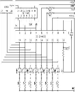
The line voltage sensor is used her e is half-wave r ectifier at the output of variac. High valued r esistant is used at the output of the r ectifier as it can sense any change at the line voltage. This r ectifier gives the dc value which is pr oportional to the ac line voltage. The r ectifier is connected to the analog input of the ZN448 ADC. The variation of line voltage is sensed by the voltage sensor and thr ough the ADC it is converted to digital fr om analog [6]. The char acter istic of the input curve is linear . After conversion the digital output enters into the 16 -Bit Micr opr ocessor Lear ning/Development System using Intel 8086 Architectur e. This system is actually a single boar d microcomputer which is based on Intel 16 bit 8086 micropr ocessor . This boar d has eight seven segment display units, tw o sets of keypads each of sixteen keys. One is the hex keypad and another is contr ol keypad. For the inter facing this development system has thirty four pins and via these it communicates with the r est of the wor ld. These pins r epr esent the thr ee I/O ports of 8255 IC, Port A, Port B -and Port C. Pow er Supply Unit consists of (+5V, +12V, -12V, BZC, PZC, NZC and LVAC). Ther e is
2Kb RAM and pr ovision for RAM extension for writing
softwar e and stor ing the data. In the ROM the monitor pr ogram of the computer is stor ed. Ther e is a 4K EPROM wher e a lookup table in the softwar e has been stor ed. A single bit data fr om the Port A contr ols the write signal of the ADC. The digital signals fr om the output of ADC enter into the accumulator thr ough the Port B and stor ed in the RAM [6,7,9]. At the same time the equivalent line
Inte rnatio nal Jo urnal o f Sc ie ntific & Eng inee ring Re se arc h, Volume 3, Issue 2, Fe bruary -2012 1
ISS N 2229-5518
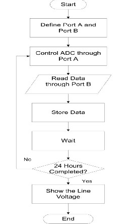
voltage in hexadecimal value is displayed in the display unit. The subsequent data ar e stor ed in the RAM and displayed in the display unit in the same way.
Fig.3. Schematic Diagr am of AC Line Voltage r ecorder
III. EXP ERIMENT AL DAT A
Tab le – I Voltage acr oss t he differ ent point of the Sensor
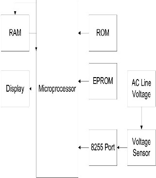
Fig. 1 Flowchart of Pow er Recor der
Table-II Line voltage value and pr oportion al ADC input value
Fig.2. Block diagram of Micr opr ocessor based Pow er
Recor der .
2
Inte rnatio nal Jo urnal o f Sc ie ntific & Eng inee ring Re se arc h, Volume 3, Issue 2, Fe bruary -2012 1
ISS N 2229-5518
Table – III Line voltage and pr oportional Hexadecimal value
Line vo ltage (Vac ) in vo lt | He xadec imal o utput o f ADC | Dec imal value o f the he xade c imal in vo lt | Line vo ltage (Vac ) in vo lt | He xadec imal o utput o f ADC | Dec imal v alue o f the he xade c imal in vo lt |
245V | F4 | 244 V | 210V | D2 | 210V |
240V | F1 | 241 V | 205V | CE | 206V |
235V | EB | 235 V | 200V | C8 | 200V |
230V | E7 | 231 V | 195V | C3 | 195V |
220V | DC | 220V | 185V | B8 | 184V |
Table – IV
Line voltages incr easing and decr easing dur ing the variac us ed exper iment and the corr esponding hexadecimal values are stor ed in the memory locations
(0-250) (incr easing); (250-0) (decr easing)
Me mo ry loc atio n | He xadec i mal Data | Me mo ry loc atio n | He xade c imal Data | Me mo ry loc atio n | He xadec imal Data | Me mo ry loc atio n | He xadec imal Data |
1201 | 00 | 1214 | 21 | 1224 | C4 | 1235 | 75 |
12007 | 00 | 1217 | 2A | 1227 | DC | 1238 | 4B |
1208 | 02 | 1218 | 2A | 1228 | E6 | 1239 | 42 |
1209 | 02 | 1219 | 33 | 1229 | ED | 123A | 35 |
120A | 03 | 121A | 39 | 122A | EC | 123C | 1A |
120B | 04 | 121B | 3B | 122B | EE | 123D | 1A |
120C | 07 | 121C | 3F | 122C | EC | 123E | 14 |
Table –V Recor ding line voltage dir ectly w ithout variac
Me mo ry loc atio n | He xadec i mal Data | Me mo ry loc atio n | He xadec i mal Data | Me mo r y loc atio n | He xadec imal Data | Me mo ry loc atio n | He xadec imal Data |
1200 | 00 | 1220 | ED | 1237 | 02 | 1262 | 77 |
1201 | 00 | 1221 | ED | 1238 | 01 | 1263 | 5B |
1202 | DD | 1222 | EE | 1239 | 00 | 1264 | 45 |
1203 | EC | 1223 | ED | 123A | 00 | 1265 | 35 |
. | . | 1224 | EE | . | . | 1266 | 28 |
. | . | 1225 | EE | . | . | 1267 | 1E |
1209 | EC | 1226 | EE | . | . | 1268 | 17 |
120A | ED | 1227 | EE | 1242 | 00 | 1269 | 11 |
120B | ED | 1228 | CF | 1243 | ED | 126A | 0D |
. | . | 1229 | 9F | 1244 | EE | 126B | 09 |
. | . | 122A | 78 | . | . | 126C | 07 |
A. Result Analysis and Discussion
The Pow er Recor der keeps r ecor d of tw enty four hours and is able to the show voltages fr om 190V-250V. It keeps a r ecord of 1240 r eadings. It can give r eading up to two
decimal digits. Our system is capable of measur ing line voltage at any place.
3
Inte rnatio nal Jo urnal o f Sc ie ntific & Eng inee ring Re se arc h, Volume 3, Issue 2, Fe bruary -2012 1
ISS N 2229-5518
IV. CONCLUSION
At pr esent this system is a dedicated inter face cir cuit but w e can design it for the commer cial purpose for stor ing various line voltage data which will be handy portable. Since it is a local pr oduct, it w ill cost lesser than the impor ted ones.
REFERENCES
[1] S tuart R. Ball, “Embe dde d mic ro processo r syste ms: re al wo rld de sig n”, 3rd wd., Else v ie r Scie nce , IS BN : 0 -75006-7534-9, pp-121-129.
[2] Intel Microprocessor Reference Guide, April 2002. (http://www.inte l.co m/pressroo m/kits/quic kre f.htm)
[3] Tre de nnic k, Nic k. Microprocessor-Ba sed Computers for
Professiona ls. Oc to be r 1996, Vol. 29 , No. 10 pg . 27-36
[4] http/w.w.w. futurlec .co m/Me mo ry /2732.shtml.
[5] Priv ate Doo r Ope ne rs. 2006. “Priv ate Doo r Info rmatio n”.
Lo mbard, IL. http://www.priv ate doo r.co m.
[6] Hall, Do ug las V . 1991. Mic ro proce sso rs and Inte rfac ing Prog ramming and Hardware . 2nd e ditio n. Gregg Co llege Div isio n: Ne w Yo rk, NY.
[7] A. P. Gupta. TimingVerifica tion of Microprocessor-ba sed Designs.
PhD
the sis, ECE De partme nt, Carneg ie Me llo n Unive rsity , 1994.
[8] Ontario Hy dro , Ontario Po we r Ge nratio n Hy dro o ne e ne rgy e ffic ie ncy g uide -Po we r Quality .
[9] Mic ro proce sso r Data Boo k S.A Mo ney T.Eng (CEI) MITE, Farne l Se mico nduc to r Data CD -ROM, Issue 7 January 2000, Datashee t 2143, PDF. 7805 IC
[10] http://www.upde sig ns.co m/
[11] http://www.mic ro proce sso r-de sig n.co m/
[12] http://e n.wikiboo ks.o rg/wiki/Mic ro processo r_Desig n
[13] http://www.inte l.co m/e duc atio n/de sig n/
4