International Journal of Scientific & Engineering Research, Volume 6, Issue 4, April-2015 1012
ISSN 2229-5518
Design and Automation of IGBT Test Fixture
Using PLC
Savitha Pareek#, Ritesh Singh^, John Paul! , Hitesh Dhokiya*
# M.Tech Scholar, Manipal University Jaipur
^ Assistant Professor, Department of EEE, Manipal University Jaipur
! Senior Manager Schneider Electric India Pvt ltd
* AGM Schneider Electric India Pvt ltd
—————————— ——————————
HE static and dynamic characterisitics of insulated gate bipolar transistor (IGBTs) play an important role in ana-
2. It has dedicated electrical connections conform to
OUTPUTS with exclusive OUTPUT number
lyzing the behavoiur of parallel current IGBTs. Over the
past few decades, developments in power semiconductor have
led to fast advance of high power IGBTs [1]-[5]. Although the
output current is very high it finds application in high power
industrial application such as inverters, pulse regulators and
frequency regulator drivers. In order to understand the char-
acteristics parameters these IGBT have to be tested each time
in a controlled environment. Traditional measurement system such as oscilloscopes and meters do provide a high resolution and accuracy, but when it comes to implement such a system in a production or industrial assembly line where harsh envi-
3. A controller that is as simple as a computer.
PC C-RIO
TESTER/
TEST CIRCUIT
ronment persist it leads to limitations such as stability, inaccu- racy in measurements and high cost. Also manual testing of IGBTs was time consuming and tedious as it involved human resource and slowed the process. In order to reduce and re- move such constraints posed by these system, we have de- signed an automated tester using PLC (programmable logic controller).
PLC
FIXTURE
DISPLAY
IGBT
We have used PLC as a choice of automation as it was rug- ged enough to perform reliability in the plant floor environ- ment with extreme temperature and humidity, airborne dust and particulates. Another significant feature involved its straight forward connection between the host and the com- puter. The tremendous success of PLC’s is because of its pro- gramming language chosen i.e. relay ladder logic. The close correspondence of ladder logic to relay circuits was the main reason for the PLC to be chosen for the IGBT test fixture as it provided the pictorial programming interface with graphical representations with relay and switches.
Apart from the most complex PLC every other PLC have some common components:
1. It has dedicated electrical connections conform to IN- PUTS with exclusive INPUT number
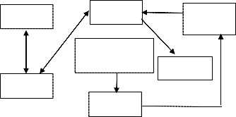
The above block diagram shows the entire test set-up fixture which consist of a PLC (Schneider PLC), National instrument’s C-RIO, Fuji IGBT which has been used for the experimental purpose, Pc for displaying the measurement values.
In this set-up the IGBTs are tested by placing the IGBTs in the fixture which is pneumatically controlled by the PLC via the pressure signal and component detect sensor, while the meas- urement signal are measurement by the C-RIO based on the test circuit designed to measure the various parameter under the controlled environment .
C-RIO- A Compact real I/O system (C-RIO) is rug- ged hardware architecture includes I/O modules, a
IJSER © 2015 http://www.ijser.org
International Journal of Scientific & Engineering Research, Volume 6, Issue 4, April-2015 1013
ISSN 2229-5518
reconfigurable FPGA chassis, and an embedded con- troller for communication and processing, and real time deterministic data acquisition. By the use of em- bedded controller good execution for the Real-Time application is possible. The user-programmable FPGA, hot –swapped I/O modules for data acquisi- tion and control, and graphical Lab VIEW software for rapid Real-time, Windows and FPGA program- ming is mounted on the reconfigurable chassis.
IGBT Module- the IGBT’s used in the testing process is a Fuji V-series Module, having 1200V/600A/1 in one package. Having the feature of high speed switching, voltage driver and low inductance module structure.
Pneumatic controls are very common in industrial use, primarily for applications that require a fixed distance travel of or reciprocation of objects. Examples include transfer of materials between conveyors, clamping objects for assembly or testing, punch presses etc. Compressed air is used to gener- ate the actuating action.
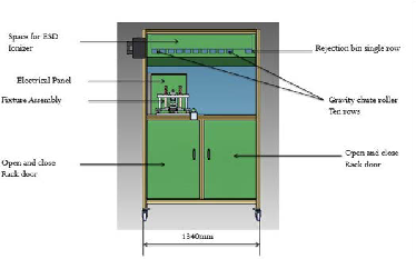
Manually placing the component on the sliding fixture and manually sliding the fixture under the pneumatic cylinder. The distance between the component and the pneumatic cyl- inder attached with the Derlin pad will be approximately
10mm. When the component is pressed to bottom which has spring loaded electric probes at the bottom touches the com- ponent and the signal is given to the PLC then the signal is received by NI from the PLC the test is performed. If the com- ponent is ok then the pneumatic cylinder moves up and the component comes up as it has spring loaded electric probes. And the component along with the sliding fixture moves back to the initial stage manually and the component is removed manually. If the part is not ok then the pneumatic cylinder does not move up at that point of view we need to click the acknowledgment switch and make the pneumatic cylinder move up. And then the component has to be placed in the re- jection bin until and unless the rejected component is not
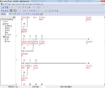
The Plc circuit is designed for the movement of the jig up- wards and downwards such that it provides the connection establishment between the IGBT and the Test Circuit (De- signed for the static Parameter Measurement of IGBT) with the help of pogo pins and power probes.The input and the output signals are shared between the plc and C-RIO.
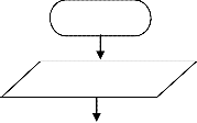
Start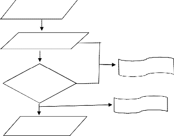
Machine Ready
Contact- Established
Cycle start
Test incomplete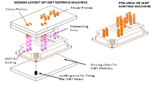
placed in the rejected bin the machine does not allow testing the next component.
hine does not allow testing the next component.
Test No
Completed
Yes
Test completed
Contact
De-established
Stop
IJSER © 2015
International Journal of Scientific & Engineering Research, Volume 6, Issue 4, April-2015 1014
ISSN 2229-5518
The Machine ready signal is set to initiate the system start, this signal is set when the control on signal is given from the C- RIO and there is no emergency stop is switched. Once the ma- chine is ready with all the initial settings the position of the jig is monitored for its position (whether it is in top or in contact with IGBT) Top Position Sensor is set once the machine is ready and an acknowledgement signal is received from C-RIO and reset is not activated.
3 major Constraints are checked to stop the system operation i.e.., safety, part presence and cycle start.All the three are monitored by providing the time delay (ON DELAY TIMERS are used).If the safety switch input is not provided from the crio or If Igbt is not detected else the top position sensor is not set then the system is interrupted from the operation.
Once the system is started i.e.., the connection is established the cycle start signal is sent so that the jig is not disturbed such that the static characteristic parameters of IGBT are measured. The safety switch is strictly monitored since a high current is flowing in the circuit.
Once the cycle has started and the results of parameters are drawn a signal is generated indicating whether the test is suc- cessful are not. If it is successful then the contact is released by making the higher position sensor to be on otherwise contact is not disturbed and a fresh cycle start is initiated on a manual demand.
IJSER © 2015 http://www.ijser.org
International Journal of Scientific & Engineering Research, Volume 6, Issue 4, April-2015 1015
ISSN 2229-5518
Sr.NO | Parameter | Semi- automated system | Traditional system |
1. | Reliability | high | low |
2. | Labor | low | high |
3. | Process Time | low | high |
4. | Amount of production | high | low |
5. | safety | high | low |
Conventional Test platform | Cost in INR | C-RIO platform | Cost in INR | Difference |
High End oscilloscope | 9,21,000 | NI-922 AI- Module | 72,300.00 | 9,19,795 |
Switch Con- trol Unit | 2,25,540 | NI 9774 | 19,500 | 2,06,040 |
FPGA Con- troller and multicore processor | NA | NI 9068 | 2,64,000 | 2,64,000 |
In this paper we have presented a complete designing of IGBT test fixture based on PLC and C-RIO platform. The au- tomation system provided here enables maximum number of IGBT to be tested for its characteristics evaluation and gives an excellent performance within the controlled environment. The use of PLC for the controlling action of the system efficiently results in good production for the high power industrial ap- plication.
The application can be extended for testing the IGBTs using the IGBT Test Fixture under high controlled environment. Al- so the entire process can be made fully automated without the interruption of human.
We are thankful to Schneider Electric India Pvt ltd for their valuable concepts of the project and technical support during the entire project phase. We are grateful to Prof. (Dr.) Shara- van Kr Jhajharia, HOD EEE department Manipal University Jaipur for his kind support and guidance.
[1] Xuesong Wang, Zhengming Zhao and Liqiang Yuan,12-
16 September 2010 “Current Sharing of IGBT Modules
in Parallel with Thermal Imbalance,” IEEE
[2] Romeo Letor .Mar/Apr 1992 “Static and dynamic be- havior of paralleled IGBT’s,” IEEE Trans. Ind. Applica- tion., vol. 28, no. 2, pp. 395-402
[3] S. Brown "FPGA architectural research: A survey", IEEE Des. Test. Computing., vol. 13, no. 4, pp.9 -15
[4] S. Nabi , M. Balike , J. Allen and K. Rzemien,2004 "An overview of hardware-in-the-loop testing systems at visteon", Proc. SAE Conf., pp.13 -22
[5] National Instruments” NI cRIO-9068: Performance and
Throughput Benchmarks” white paper
[6] P. Hofer-Noser and N. Karrer, “Monitoring of paral- leled IGBT/diode modules,” IEEE Trans. Power Elec- tron., vol. 4, no. 3, pp. 438–444, May 1999.
[7] P. Hofer-Noser, N. Karrer, and C. Gerster, “Paralleling intelligent IGBT power modules with active gate- controlled current balancing,”in Proc. 27th IEEE Power Electron. Spec. Conf., 1996, vol. 2, pp.1312–1316.![]()
IJSER © 2015 http://www.ijser.org