International Journal of Scientific & Engineering Research, Volume 6, Issue 4, April-2015 439
ISSN 2229-5518
Design Model of Built-up-Stiffened Column Base under Large Eccentric Load
Biswajit Som1, Sandip Maity2, Gokul Ch. Mondal3 and Satchidananda Sur4
ABSTRACT: Design of Column base connection is more complex than other steel to steel connection in a structura l system due to its concrete interface. Till recent past, column base connection was least studied structural connection. Analysis and design concept of steel column bases are changing rapidly in recent years. Ongoing experimental research and studies show that the column base behavior changes significantly beyond the elastic regime and its design limit state shall be derived based on actual failure state of a column base connection. Recent publication of codes and design guides in European Union, United States and Japan on column base depicts some major changes from traditional concept and practical design approach. However recent research on the column base is more concentrated on unstiffened base rather than stiffened column base connection subjected to very large moments. In practical design, for a heavily loaded moment resisting frame, large stiffened base connection is unavo idable. In this paper a brief review of new concept of column base behavior have been validated by finite element simulation. Here an attempt has been made to develop a suitable design model by flow chart and numerical example of built-up stiffened base subjected to large eccentric load with appropriate detailing for practical design purpose.
KEYWORDS: Steel Structure, Rigidity, Column Base, Stiffened, Built-up, Plastic, Failure Mode
1.0 INTRODUCTION
olumn base connection of any steel frame structure is fundamentally different from other connections of a structural system due to its critical interface with less ductile foundation material like concrete/grout. Experience shows building collapse resulted from failure at the column base connection in many cases under wind and earth quake load. Base failure of a steel frame column may lead to a complete collapse of the structural system as there are least chances to have any other parallel path to transfer the load to its foundation. Apart from the total failure, the column base connection has a countless effect on the performance of a frame structure. Practicing structural engineers sometime overlook the major significance of this connection from design, detailing and constructability point of view. Unfortunately, a standardized or codified design model is not always available to practicing engineers in India and many other countries. Sometimes structural engineers are to rely upon the available text book where also design concept and detailing varied considerably from author to author [32,33,34,35,36,37] Generally in practical design, column bases are modelled as fixed or hinged but in real world situation it is neither fully fixed nor fully hinged. It is somewhat between these two extreme [26]. Decision and planning regarding the support system (condition of restraint) in modelling of a steel frame is actually the start of column base design. This design decision depends on various factors starting from foundation capacity to frame demand for a particular building structure.
___ _ _ _ _ _
1Director, EISPE, Structural Consultant, & Guest Faculty, Department of Construction Engineering, Jadavpur University
2Design Engineer, EISPE, Structural Consultant
3Associate Professor, Department of Construction Engineering, Jadavpur University
4Fellow, Institute of Structural Engineers, London, & Consulting
Engineer
In recent time it is established that earthquake load demands
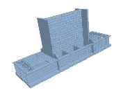
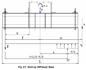
more rigidity of the column base connection as also recommended in IS 800-2007 to withstand more (plastic) deformation before failure [38]. Rigidity of column base connection and its high rotational stiffness demand can only be achieved by appropriate detailing of stiffening components with plastic potential. A more rigid base detail other than ordinary stiffened (gusseted) base, may be termed as built-up stiffened base which is an acceptable solution to the problem. A typical built-up stiffened column base is shown in Fig.-1.
Fig.-1: Built-up Stiffened base
2.0 MODERN CONCEPT OF COLUMN BASE DESIGN
Recently some significant advancement has been made in
experimental research and numerical study of column base
connection. On the onset LRFD/Limit state design method and use of SMRF (special moment resisting frame) in seismic zone gave impetus on this research area. Philosophy of limit state of failure prompted the structural engineer to understand the actual failure mode of this connection beyond elastic range to assess the plastic capacity of the connection. Formation of plastic hinge in different components of connection and inelastic response become an important consideration for safe and economic design of the connection. Practical Design procedure of stiffened column base is still not widely available in international code and literature. However the basic overall behaviors of stiffened and unstiffened base are similar but the practical design approach considering the inelastic behavior of stiffened base
IJSER © 2015 http://www.ijser.org
International Journal of Scientific & Engineering Research, Volume 6, Issue 4, April-2015 440
ISSN 2229-5518
requires more experimental and numerical verification. Basic design approach as practiced in major countries in the world in recent time has been briefly presented here.
a) European approach: European approach of design is
based on recently published EN 1993-1-8. The design of
exposed unstiffened column base is included in this standard. This approach is based on decomposition of individual failure modes of components comprising the whole connection. For design resistance of column base considered as i) Base plate and concrete block in compression ii) Base plate in bending and anchor bolt in tension iii) column web in shear and flange in compression and tension iv) Anchor bolt and shear key in shear. European approach also considers flexible behavior of plate by equivalent rigid plate area concentrated mainly under the footprint of the flange of a column (I-section) and the distribution of concrete stress underside of the base is rectangular. Concept of ‘T Stub’ component consists of column flange or web and under lying base plate as T-element included in this approach considering stiffer concrete response than plate. This approach emphasize on the quality of concrete and grouting work for overall stiffness of column base component.
b) US approach Design procedure of column base in US upgraded rapidly. AISC Design Guide-1[27] First edition published in 1990 revised in 2006[28] as second edition where triangular stress block (TSB) concept has been revised to rectangular stress block (RSB) concept. Further a report on extensive research has been presented to AISC by University of California and Stanford University in 2010[29] with necessary update of AISC Guide -1(2006). This show how fast the new concept on column base design is emerging. It shows through large number of experiment, the initiation of failure stage after formation of plastic hinge on the compression side of base plate, anchor bolt strength becomes independent of concrete bearing stress. Formation of plastic hinge in tension side leads to final collapse of the system by formation of mechanism. The flexibility of the base plate is practically ignored by considering a minimum concrete strength under full width of the base plate. The minimum concrete strength has been modified by ratio of loaded base area and concrete foundation to avoid bursting failure of the concrete pedestal due to un-confinement of the stress bulb at the underside of the base. It also shows that the chance of concrete bearing failure is very low as the flexibility and ductility response of the plate is a reality. Before crushing of the base concrete the plate will yield and proceed towards formation of plastic hinge.
c) Indian approach- IS 800-2007: Limit state code published in 2007 has presented a very brief outline for slab (unstiffened) and gusseted (stiffened) base. Flexibility of base plate and equivalent rigid concept of base under axial load have been incorporated. Categorical recommendation on the shape of concrete stress block is not available. Column base with
eccentric loading has been referred to as ‘special literature’ [38]. So design guideline of column base in Indian code is highly inadequate.
d) Concept of Strength Prediction of column base

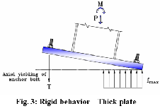
Adequate rigidity of base plate is a basic requirement for intended design performance of any moment resisting frame structure. Thickness of the base plate, is one of the most significant parameters that affects the response of such steel connections [5]. In traditional design, triangular stress distribution on concrete base is considered and the plate is assumed as remain plain under applied moment which is not consistent with actual ductile behaviour of plate leading to concrete bearing failure as shown in Fig.-2. It is considered and adopted by many international codes that the stress distribution at concrete and plate contact area can be assumed as rectangular. Ductility response of the steel plate towards inelastic regime is more emphasised in new strength evaluation concept. Steel is more ductile than concrete. Steel plate deformed (bend)
more than the
concrete. Steel plate bends and plastic
hinge is formed
in
Fig. 2: Triangular Stress Block (TSB)
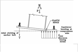
compression side leaving the concrete unyielding. This is established by experimental research. Tradition concept of rigid plate behaviour (see Fig.-3) does not conform to actual behaviour. Moreover formation of plastic hinge in compression side only does not produce a mechanism of failure (See Fig.4).
Failure
mechanism requires another component or part to reach its yielding state for e.g. anchor bolt yielding in tension or another plastic hinge in tension side (See Fig.5). This behaviour of column base has been studied by Finite Element Simulation of model with magnified deformation diagram.
3.0 FINITE ELEMENT ANALYSIS OF COLUMN BASE
IJSER © 2015 http://www.ijser.org
International Journal of Scientific & Engineering Research, Volume 6, Issue 4, April-2015 441
ISSN 2229-5518
3.1Modelling:
Finite element method is now widely used and is a well- accepted tool for accurately simulating complex structural systems, FE analysis have been done by STAAD V8i, Bentley structural analysis and design software. Finite Element model for column base plate simulated on the basis of the following:
General behaviour of the column base in the 2D plate finite element model depicts some important fact as summarized below:
Fig.-4: Plastic Hinge on Compression side
To achieve the actual behavior of the base connection, the continuous support on concrete have been ignored and discretization of continuous plate to finite element mesh has
Fig. 5: Flexible behavior - Thin plate mechanism
Fig.-6 Thinner Plate: Low base contact
i) Traditional approach of design of axially loaded column base (pinned) considered as rigid and distribution of pressure under base is uniform over concrete pedestal/grout. But in case of a flexible plate the pressure concentrated around the foot print of column section. This occurs due to the lifting of plate through bending around the column section. The saucer shape of the plate under axial load can be found in Fig.-6, for thin plate. This conforms to the equivalent rigid region of the plate under active compression. This actual behaviour of unstiffened base under axial load is codified in different code including the IS: 800-2007.
ii) It is found from the Fig.-7, with the increase of thickness of base plate the lifting of plate is reduced and thereby contact
between the concrete/grout and the plate increased which shows the rigidity of base plate is an important consideration with thickness of plate or stiffness of plate.
been done to make the nodes as support by applying spring constant concrete with assumed E=25000N/mm² (M25) (K =
1650 Ton/m). Reaction from concrete base is simulated as
‘compression only’ (unidirectional spring) has been generated
and had been assigned at each node except the anchor bolt position.
Axial elongation of anchor bolt is ignored. Column, base
plate and stiffeners connections considered as rigid connection at nodal points to simulate the real behaviour of the connection.
3.2 FE Analysis:
Following base connections have considered for analysis
Base plates with compression only shows the plate behaviour and its flexibility with plate thickness and stiffened condition.
Stiffened Base with compression and large moment-a)
Wide plate b) Long built up base
Fig.-7 Thicker Plate: Base contact increased
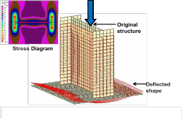
iii) Figures 8a & 8b show if the base is stiffened, rigidity of the plate is increased further.
In fig. 8a finite element model of stiffened (gusseted) column
base under axial compression and heavy moment with wide
base configuration is shown. It is found in fig. 8b that the contact area of base and concrete/grout becomes ineffective across the width of the plate even though it is stiffened. In tension zone more number of anchor bolts can be geometrically accommodated, but due the ineffective area of
IJSER © 2015 http://www.ijser.org
International Journal of Scientific & Engineering Research, Volume 6, Issue 4, April-2015 442
ISSN 2229-5518
base plate across width makes the exterior bolt less loaded and redundant. AISC Guide -1 assumed a moment line as shown in Fig.8c for economic and effective shape of baseplate trial size.
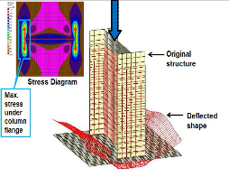
iv) Fig. 9a & 9b show FEM of stiffened (built-up) column base
with axial compression and heavy moment with long
(moment along major axis of column) base configuration.
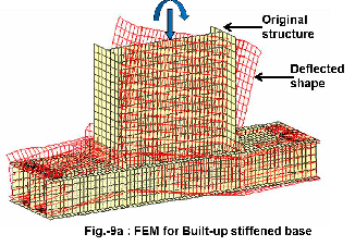
It is found that the contact area of base and concrete/grout becomes effective across the width (smaller) of the plate. Plate projection all along the width is stiffened by providing built- up beam section with wide flange joist and channel and partial top and bottom plate [See Detailed Sketch]. In tension zone less number of anchor bolts is used and the effective area of base plate across the width makes all the bolt carry nearly equal tension. Moreover it can also be observed that rotational stiffness of the column section is adequately increased if compared with unstiffened or single plate stiffened base [Gusseted].
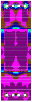
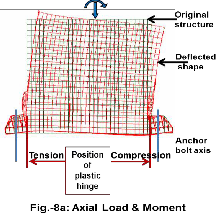
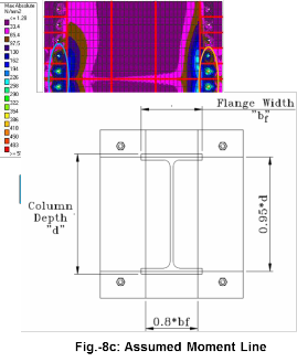 Fig.-9b : Stress Diagram
4.0 FLOW CHART FOR DESIGN MODEL OF BUILT-UP STIFFENED BASE
IJSER © 2015 http://www.ijser.org
International Journal of Scientific & Engineering Research, Volume 6, Issue 4, April-2015
ISSN 2229-5518
443
Based on findings of FEM of column base especially for stiffened built up base and the modern concept of strength prediction of column base a design process in line with present AISC approach can be presented as Design Model in the form of a flow chart.
r---------------------------5-.-0-D-E--S-IG-N--M-O--D-E-L-(EXAMPLE) OF COLUMN
( Approach as per AlSC Design Guide-12nd edition, 2006 }

Design Data
•Column Axial load, Moment (M u}, Base Shear
•Column Size
•Character istic strength of concrete (f'*) and grout.
• Concrete pedestal area (A2).
•Coeff icient of friction ht} between steel base and concrete
•Yield stress and ultimate tensile stress of steel and fasteners
(Fvf F,jFvJFubl·
Fi x Assumed Moment
line Select trialsize of base plate based on
column dimension & Moment line
z0
'::
• Determine maximum bearing stress I
minimum Strength on concrete ( fp(max.) }
• Determine maximum bearing force per mm width of plate (qmaxJ
Large moment
Nominal anchor rod required
Case not detailed. Only large moment considered.
Determine:
• Anchor rod tension (T,od ).
• Moment at bearing interface
( M oompressioJ •
• Moment at tension
( Mt•nsion ·
Determine number of anchor Bolt
If No
Stiffened/Built-up column base
Design Given in Example form
Check minimum strength of base by choosing maximum of
Mcompression and Mtension and calculate thickness (tp} of unstiffened
column base
Design complete
Go for Stiffened/
built-up base
Ill
Ql
>
If No
BASES WITH LARGE MOMENTS: (In accordance with Design Model Flowchart)
IJSER ©2015
http://www ijser ora
International Journal of Scientific & Engineering Research, Volume 6, Issue 4, April-2015 444
ISSN 2229-5518
Design Philosophy:
Rectangular stress block (RSB) method of design has been adopted considering the inelastic behavior of the system. Different failure modes of the column base have been identified and are checked in the course of design.
Failure mode 1: Yielding of base plate on the compression
side and tension side whichever occurs early.
Failure mode 2: Yielding of base plate on the tension side
and axial yielding of anchor bolt whichever occur early
Failure mode 3: Axial Yielding bond failure of anchor rods and yielding of base or stiffeners.
Design Parameters
Grade of conc. = M25, Depth of col. = 890mm Width of col.
=300mm, Thk. of web =16mm Thickness of flange =30mm,
Class of bolt =8.8
fyb =640N/mm2, fub =800N/mm2, ftb = 576N/mm2
fvb =369.5N/mm2, Bond stress =1.4N/mm2 , fy =250N/mm2, fu =410N/mm2
Dbolt =36mm
Tensile stress area of bolt =817 mm2
Standard clearance =3mm
γm0 =1.1 γm1 =1.25
Factored axial load, Pu =187.5T
Factored moment, Mu = 412.5Tm
e =2200mm
Trial 1.Unstiffened Base: Assume: width =1000mm Length =1300mm
Concrete area supporting base plate: Width =1100mm
Length =1400mm
fp(max.) = (0.45 x fc' ) x √(A2/A1) = 12.24N/mm2 (Refer IS:456-
2000 Clause 34.4)
qmax. = fp(max.) x width of base plate = 12240N/mm
ecrit. =(L/2)-(Pu/2*qmax.) = 573.41mm<2200mm
Large moment
Y= 434.34 mm, Real solution of Y exist.
Base plate size ok.
Anchor rod tension, Tu =qmax. Y - Pu = 344.13 T
No. Of 36mm diameter bolts required = 8
No. Of bolts is high which produces uneven tension in bolts. Long base preferred.
Mcomp. = 0.09 T-m/mm Mtens. = 0.03 t-m/mm tp(reqd.) = 126.12 mm
Very high thickness, adopt stiffened base.
Trial 2. Stiffened Long base:
From calculation, stiffened long base is found unsuitable to high demand of cantilever moment in tension and
compression side. Stronger cantilever sections like built-up box with compact or plastic local capacity is preferred.
Trial 3. Built-up stiffened base:
Size: L = 3000 mm, B = 700 mm , Depth of box section
(cantilever) = 630 mm (Assumed)
Concrete area supporting base plate : Width =800 mm
Length =3100 mm (See E1 and Design Sketch). fp(max.) = (0.45 x fc' ) x √(A2/A1) = 12.23 N/mm2 qmax. = fp(max.) x width of base plate = 8561 N/mm ecrit. =(L/2)-(Pu/2*qmax.) = 1390.49 mm
f =L/2-(edge distance) =1380 mm
(f+L/2) = 2880mm
(f+L/2)2 = 8294400mm2
2*Pu(e+f)/q(max.) = 1568157.93mm2
Check if:
(f+L/2)2>2*Pu(e+f)/q(max.)
8294400 >1568157.93
The inequality is satisfied and a real solution for Y exists
Y = (f+L/2)+ √((f+L/2)^2-(2*Pu(e+f)/q(max.)) =5473.5mm
>3000mm, which is invalid.
Y = (f+L/2)- √((f+L/2)^2-(2*Pu(e+f)/q(max.)) = 286.5mm.
Hence Ok
Anchor rod tension, Tu =qmax. Y - Pu =57.77T
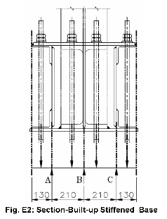
Local strength check for individual component of stiffener:
(See Fig.E2)
Local bending strength is checked considering the top cap plate as a continuous beam with anchor rod tension as concentrated load and vertical components of built-up base as support.
Width of top cap plate at anchor bolt position =200mm
Thickness of top cap plate at anchor bolt position =20mm
Concentrated load =57.77T
Bending moment:
Support moment at A = 1.01T-m Support moment at B = 0.09T-m Support moment at C =1.01T-m
IJSER © 2015 http://www.ijser.org
International Journal of Scientific & Engineering Research, Volume 6, Issue 4, April-2015 445
ISSN 2229-5518
Span moment between A-B =0.277T-m
Span moment between B-C =0.277T-m
Thickness required at A & C : ZpxFy/γm0 = 10100000Nmm trequired = 30mm
Thickness of plate required = trequired - Leg thk. of angle
=18mm< 20 mm (tprovided) HENCE OK
Thickness required at B : ZpxFy/γm0 = 900000Nmm trequired = 9 mm< 20 mm (tprovided)
HENCE OK
Thickness required at due to span moment: ZpxFy/γm0
=2770000Nmm
trequired =16 mm< 20 mm (tprovided) HENCE OK Check for local buckling of stiffener under shear Total Shear force at A = 24.35 T
Total Shear force at B = 9.06 T Total Shear force at C = 24.35 T
Shear area provided at A & C =11920 mm2
Shear area provided at B = 7670mm2
Shear area required at A & C = (VA x √3 x γm0)/Fy
= 1855.72 < 11920 mm2, HENCE OK Shear area required at B = (VB x √3 x γm0)/Fy
= 690.46 < 7670 mm2 HENCE OK
Note: Chance of early Local failure of bottom plate in
compression side due to the local bending moment is less
Strength check of the built up base
i) At face of column
Plastic section modulus, Zp= 19098764.44mm3
At bearing interface:
Moment at compression side, Mcompbase
= 2.291E+09 N mm
Design bending strength = βbxZpxfy/γmo
= 434.06 T-m > 229.08 T-m HENCE OK
At tension interface:
Bending moment at the tension side due to tension in anchor rods, Mtensbase = 5.4E+08 N-mm
Design bending strength = βbxZpxfy/γmo
= 434.06 T-m > 54.01 T-m HENCE OK
ii) At end of top cap plate
Plastic section modulus, Zp = 13946147.07 mm3
At bearing interface:
Moment at compression side, Mcompbase
= 1.923E+09 N mm
Design bending strength = βbxZpxfy/γmo
= 316.96 T-m > 192.29 T-m HENCE OK
At tension interface:
Bending moment at the tension side due to tension in anchor rods, Mtensbase =4.53E+08 N-mm
Design bending strength = βbxZpxfy/γmo
= 316.96 T-m > 45.35 T-m HENCE OK
Check for shear at critical section:
Shear force at Tension interface = 57.77 T
Shear force at Bearing interface = (12.23*286.5*700)/10^4 =
245.27 T
Maximum Shear at critical section = 245.27 T Shear area provided = 31510 mm2
Design shear strength = Vd = (Av.fyw)/(√3.γm0) = 413.46 T
0.6 x Vd = 248.076 T > 245.27 T
No reduction in moment capacity required
Determination of anchor rod size and embedment length of
anchor stud-sleeve:
Edge distance for bolts =120mm
Anchor rod tension, Tu = 57.77 T
Provide 4 numbers of bolts on the each side of column flange
Net area of bolts required = (57.77 *10^4)/ 576 = 1002.95 mm2
Net area of each bolt = 1002.95 / 4 =250.74mm2
Provide 36 mm dia bolt each giving net area = 817mm2 >
250.74 mm2 HENCE OK Embedment Length of anchor stud-sleeve:
Length of each pipe sleeve = (( 57.77 / 4)*10^4)/(3.14* 76.1 * 1.4
) = 431.7mm. (See HD bolt detail in page 8).
Provide 500mm length of anchor pipe sleeve. (Using pipe
sleeve anchor bolt embedded length is reduced). Note:
Determination of frictional resistant and shear key required for lateral shear is not included in this design model but it is preferred, shear key if required by design shall be provided under the base plate at two column flange locations.
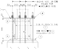
A general arrangement and detailed design sketch is
developed on the basis of the above calculation given below.
IJSER © 2015 http://www.ijser.org
International Journal of Scientific & Engineering Research, Volume 6, Issue 4, April-2015 446

ISSN 2229-5518
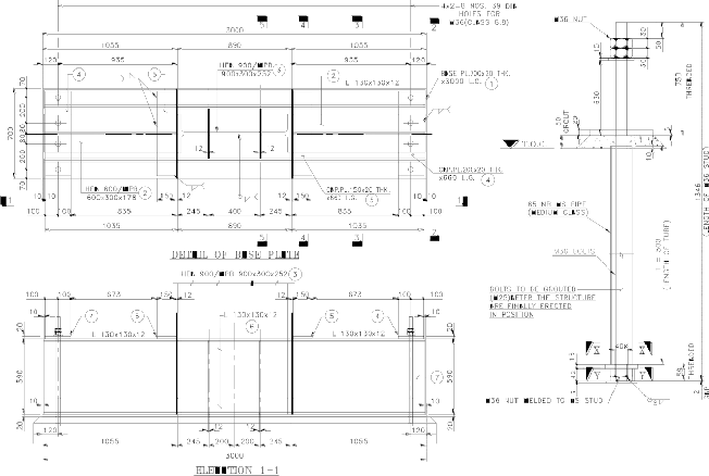

GENERAL ARRANGEMENT & DETAIL OF BUILT-UP STIFFENED BASE

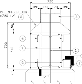

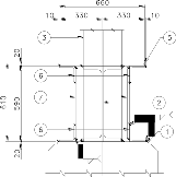

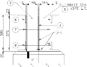


NOTES:
1. ALL DIMENSIONS ARE IN MM.
2. ALL WELD SHALL BE SHOP WELD.
3. GRADE OF STEEL Fe-410.
4. ANCHOR BOLT DETAIL SH ALL BE USED IN CIVIL DRAWING.
5. NON-SHRINK PREMIX GROUT OF COMPRESSIVE STRENGTH

NOT LESS THAN 25 N/MM² OR AS PER STANDARD DESIGN SPECIFICATION.
6.0 SUMMARY & FINDINGS

6.1Modern concept: The recent change in design concept of column base can be summarised as below.
IJSER © 2015 http://www.ijser.org
International Journal of Scientific & Engineering Research, Volume 6, Issue 4, April-2015 447
ISSN 2229-5518
i) In contrast to the elastic design the compressive bearing stresses are characterized by the rectangular stress distribution as against triangular stress distribution.
ii) The maximum bearing stress is determined as the
minimum of the bearing strength of the concrete foundation
and the bearing strength of the grout pad which is a function of base plate size and concrete pedestal/footing size supporting the base plate.
iii) The tensile capacity of anchor bolt, flexural and shear
capacity of stiffener and base plate are determined using the
ultimate material strength.
iv) A mechanism-based approach is adopted such that the
base connection strength capacity is controlled by the formation of a plastic mechanism of different component like base plate, anchor bolt, stiffeners etc.
6.2Built-up Stiffened base:
i) It is found that built-up stiffened column base is suitable for very large moment and axial load. In practice, this high eccentric load in column is generally found in large moment resisting frame for wind and earthquake condition.
ii) For very large moment, unstiffened base plate thickness becomes very high which sometime are uneconomic and unavailable.
iii) Under heavy moment, arrangement of base plate shall be such that the lever arm of bolt is higher so that the tension of
the bolt can be reduced to avoid early yielding and bond failure between bolt and concrete.
iv) For larger lever arm of anchor bolt, the base plate size shall be long enough and to make the long cantilever length stiffer against tension and compression side bending. This requires heavily built-up stiffened base.
v) As shown in detailed drawing and in FEM deformation diagram (Fig-9a) the rotational stiffness of column is increased due to raised anchor bolt and double plate arrangement.
vi) Less number of anchor bolt shall be used to achieve the effective utilization of all the bolts. If number of bolts is high
and placed much outside the assumed moment line, the exterior bolt may be underutilized and there may be a chance of overloading of interior bolts. This requires long plate with lesser width as feasible in design (refer design example).
vii) It is observed from the numerical example that the strength of base in compression side governs the design. Possible location of first plastic hinge will form at compression side which is favourable as far as the deformation of the plate is concerned.
7.0 CONCLUSION & LIMITATION OF STUDY:
On review of literature, codes and standards with development of basic design and model of built up stiffened base can give an acceptable solution of rigidity and strength
requirement for moment resisting column base with appreciable inelastic response. It is true that some practical difficulty may arise to accommodate such big exposed column base on floor. This can be addressed by encasement of the base by concrete (RCC) if required. This will further enhance the strength and rigidity of the base. Present paper is dealing mainly with the exposed base scenario and hence encasement and composite behaviour of column base is not reviewed here. Future work on encased composite stiffened-built base may be studied experimentally and analytically to obtain actual knowledge on the behaviour of the same. The design model developed here is based on the modern emerging concept of column base behaviour and failure mode. However, for practical design more study and experimental research is required for this type of column base subject to primarily bending action. In our opinion a special project may be undertaken in India based on general approach of IS 800-2007 and other international literature, code and standards to develop a comprehensive ‘design guide’ on column base (both stiffened / unstiffened and exposed/encased) through extensive experimental and analytical research. This paper can be regarded as an introductory thought in this direction.
REFERENCES
1. František Wald, Zdeněk Sokol & Jean-Pierre Jaspart. “Base plate in bending and Anchor bolts in tension”. HERON JOURNAL Vol. 53 (2008) No. 1/2
2. Martin Steenhuis, František Wald, Zdeněk Sokol, & Jan Stark. 2008, “Concrete in compression and base plate in bending”. HERON JOURNAL Vol. 53 (2008) No. 1/2
3. František Wald, Zdeněk Sokol & Martin Steenhuis. 2008.
“Component method for steel column bases”. HERON
JOURNAL Vol. 53 (2008) No. 1/2
4. Steenhuis C. M., Wald F. Sokol Z, Stark J. W. & B.
“Resistance and Stiffness of Concrete in Compression and
Base Plate in Bending”. J C S R in printing, 2003
5. Ch. C. Baniotopoulos, Z. Sokol, F. Wald. “Column base
connections”.
6. Jean-Pierre Jaspart, František Wald, Klaus Weynand, Nol
Gresnigt. “Steel column base classification”. HERON JOURNAL Vol. 53 (2008) No. 1/2
7. Massimo Latour; Vincenzo Piluso; Gianvittorio Rizzano,
2013. “Column-base plate joints under monotonic loads:
theoretical and experimental analysis”.
8. DeWolf J.T., Sarisley E.F. (1980). “Column Base Plates with Axial Loads and Mo-ments”, Journal of the Structural Division, ASCE
9. Jorge E. Grauvilardell, Daeyong Lee, Jerome F. Hajjar &
Robert J. Dexter: 2005 University of Minnesota “Synthesis of
design, testing and analysis research on steel column base plate connections in high-seismic zones”
IJSER © 2015 http://www.ijser.org
International Journal of Scientific & Engineering Research, Volume 6, Issue 4, April-2015 448
ISSN 2229-5518
10. Ali Karbakhsh Ravari, Ismail Bin Othman, Zainah Binti Ibrahim, 2010. “Finite element analysis of bolted column base connection without and with stiffeners”.
11. Dae-Yong Lee, Subhash C. Goel, Bozidar Stojadinovic,
2008. “Exposed Column-Base Plate Connections Bending
About Weak Axis: I. Numerical Parametric Study”.
12. Abubakar Idris and Ahmad Ibrahim Umar, 2007.
“Reliability Analysis of Steel Column Base Plates”
13. Holger Eggemann. “Simplified Design of Composite
Columns, Based on a Comparative Study of the Development
of Building Regulations in Germany and the United States”.
14. T.Yamanishi & K. Kasai Innovative, T.Takamatsu. 2012
“Innovative Column Base detail… “
15. Syed Firoz, S.Kanakambara Rao. “Modelling Concept of
Sustainable Steel Building by Tekla Software”.
16. Masahiro Kurata,2004. “effects of column base behavior on the overall response of steel moment frames”.
17. Charles Clifton, 2013. “Design of Moment Resisting System Column Bases to Remain Elastic under Severe Earthquake Loading: Draft Design Procedure”.
18. Victoria-elena roşca, Elena-carmen & Teleman, Elena Axinte & Georgeta băetu,2013. “Design of steel column base connections for large eccentricities”.
19. Satoshi Yamada. “Influence of the elasto-plastic behavior
of column bases on the ultimate earthquake resistance of
multi-story steel Moment frames”.
20. Ady Aviram Bozidar Stojadinovic, Armen Der Kiureghian.
“Performance and Reliability of Exposed Column Base Plate
Connections for Steel Moment-Resisting Frames”.
21. Finley Charney; Amber Verma; Maninder Bajwa; Cris
Moen. “The influence of true base connection stiffness on the computed drift of metal building frames”.
22. A. M. Kanvinde, D. A. Grilli, S. and F. Zareian. “Rotational Stiffness of Exposed Column Base Connections: Experiments and Analytical Models”.
23. M. Latour, V. Piluso & G. Rizzano Salerno, “Rotational behaviour of column base plate
Connections: experimental analysis and Modelling”
24. Abdollahzadeh, G.R. and Ghobadi, F. 2014
Mathematical Modeling of Column-Base Connections under
Monotonic Loading
25. M. R. Shafieifar & S. V. Khonsari. “Studying the
Behaviour of Base Plates with High Degree of Rigidity ”.
26. Murat Eröz, Donald W. White and Reginald DesRoches.
“Direct Analysis and Design of Steel Frames Accounting for
Partially Restrained Column Base Conditions”.
27. John T. DeWolf 7 Devid T. Becker “AISC Design Guide -1
Column Base Plate”, First Ed.1990
28. JAMES M. Fisher, and LAWRENCE A. Kloiber, “AISC
Design Guide – 1 Column Base Plate” Second Ed.2006.
29. Ivan Gomez, Amit Kanvinde, Gregory Deierlein, 2010.
“Exposed column base connections subjected to axial
compression and flexure”.
30. A.M.Kanvinde, D.A.Grill & F.Zareian “Rotational Stiffness of exposed column base connection: Experiment and analysis model”
31. Eurocode 3: Design of steel structures - Part 1-8: Design of
Joints, 2003.
32. M.R. Shiyekar, 2013. “Limit State Design in structural steel”.(book)
33. N.Subramanian. “Design of Steel Structures”.(book)
34. Edwin H. Gaylord, Jr., Charles N. Gaylord and James E.
Stallmeyer,2010. “Design of steel structures”.(book)
35. M L Gambhir. “Fundamentals of structural steel design”.
(book)
36. N.S. Trahair, M.A. Bradford,
D.A. Nethercot, and L. Gardner. “ The Behaviour and Design
of Steel Structures to EC3” (book).
37. Giulio Ballio, Federico M. Mazzolani
“Theory and Design of Steel Structures”- (book)
38. IS 800 : 2007 Indian Standard General Construction in
Steel-Code of Practice
IJSER © 2015 http://www.ijser.org