International Journal of Scientific & Engineering Research, Volume 4, Issue 8, August-2013 1990
ISSN 2229-5518
Design, Apllication and Result Analysis of
Geothermal Ventilation System
Mr.Pravin M.wale, Dr. A.C. Attar.
Abstract— Geothermal ventilation system, also called ground tube heat exchangers, is in interesting technique to reduce energy consump- tion in a building. They can cool or heat the ventilation air, using cold or heat accumulated in the soil.
The utilization of geothermal energy to reduce heating and cooling needs in buildings has received increasing attention during the last years. An earth tube is a long, underground metal or plastic pipe through which air is drawn. As air travels through the pipe, it gives up or receives some of its heat to/from the surrounding soil and enters the room as conditioned air during the cooling and heating period.
In this research work, study the parameters used in design, design a ventilation system to a building, experimental application of geothermal ventila- tion system to building. Result analysis of cooling effect is carried out.
Keywords: - cooling effect, Design Considerations, Economics, Geothermal ventilation system, Implementation.
Index Terms— cooling effect, Design Considerations, Economics, Geothermal ventilation system, Implementation, Fan Chamber, Exhaust fan.
1 INTRODUCTION
—————————— ——————————
The use of the geothermal energy re- traces to the most ancient populations, mainly in the regions where the telluric heat reaches the sur- face or in the severe climate places and was main- tained in different times of history and different parts of the world. Underground houses in villag- es and communities were also built in the Medi- terranean region and its applications in the mod- ern days have been described in many papers. It has been applied in
Buildings aimed at recreational use and constitute a good example of environmental sus- tainability.
A motor-driven compressor and a motor- driven fan are normally used in residential air conditioning systems both of them consume
Electricity is the primary power for building cooling. The electricity bill may be several times higher during summer months due to the electrici- ty consumption of the building cooling system. The electrical motor makes noise. The heat rejected to the outside pollutes the environment as well.
Earth tubes are tubes buried in the ground deep enough to take advantage of the more even year round temperature at depth. Air from outside the house is run through the earth tubes to heat or cool it before it is intrduced into the house. In the summer, the earth is cooler that the outside air temperature and the air will be cooled as it goes
————————————————
• Author name is Pravin Wale currently pursuing masters degree program in Construction Management in RIT Islampur, India,.
E-mail: pravinwale@yahoo.com
• Co-Author name is Dr.A.C.Attar Proffesor in RIT, Islampur , Countr-Indiay,. E-mail: abdulra- shid.attar@ritindia.edu
through the tubes, and the opposite in the winter Renewable energy, such as solar and geothermal energy, may provide solutions to our modern socie- ty problems. The geothermal energy may be used to provide cooling to building without use of elec- trical compressor. In fact underground soil temper- ature is much closed to supply air temperature for the building cooling. For example, the average soil temperature is about 12 ºC (53 ºF) while the cooling design outside air temperature is about 33 ºC (92
ºF) .To use underground soil as the cooling source, a cooling tube can be buried underground as a soil- air heat exchanger. The air is cooled down when it passes through the tube.

Earth cooling tubes (cool tubes) are used to cool a space by bringing outdoor air into an interior space through underground pipes or tubes. The air is cooled (and possibly dehumidified) as it travels. The cooling effect is dependent upon the existence of a reasonable temperature difference between the outdoor air and the soil at the depth of the tube. A
IJSER © 2013 http://www.ijser.org
International Journal of Scientific & Engineering Research, Volume 4, Issue 8, August-2013 1991
ISSN 2229-5518
cool tube can be used to temper incoming air when
the soil temperature is below outdoor air tempera- ture, or to provide actual space cooling effect if soil temperature is below the intended room tempera- ture. A cool tube can also be used to temper out- door air in the winter, but it will not provide any space heating effect.
In an open-loop configuration air exiting a cool- ing tube is introduced directly into an interior space (usually with the assistance of electric fans). In Figure 4.186 stack ventilation is being used, in addition to a fan, to draw cool air from the earth tube into and through the interior space.
In a closed-loop configuration room air is circu- lated through the tubes and back into the occupied spaces. The use of an electric fan makes the exam- ple in Figure 4.186 a hybrid system (as opposed to a fully passive system). In either open- or closed- loop mode, the cooling effect of the earth tubes is commonly used to reduce overall space cooling load rather than to attempt to cool a space solely with cool tubes. The cooling (or heating) contribu- tion is often focused upon cancelling the outdoor air (ventilation) load. Cooling a building exclusive- ly using earth tubes is rarely cost-effective because of the large quantity of very long tubes required to do the job. Material and installation cost would likely be prohibitive—unless there is a mitigating factor such as easy or cheap excavation.
1.1 Methods
1.1.1 Closed and Open Loops
There are two basic types of loops: closed and open. Open loop systems are the simplest.
Used successfully for decades, ground water is drawn from an aquifer through one well, passes through the heat pump's heat exchanger, and is discharged to the same aquifer through a second well at a distance from the first. Generally, two to three gallons per minute per ton of capacity are necessary for effective heat exchange. Since the temperature of ground water is nearly constant throughout the year, open loops are a popular op- tion in areas where they are permitted.
Open loop systems do have some associat- ed challenges: Some local ground water chemical conditions can lead to fouling the heat pump's heat exchanger. Such situations may require precau- tions to keep carbon dioxide and other gases in solution in the water. Other options include the use of cupronickel heat exchangers and heat exchang- ers that can be cleaned without introducing chemi- cals into the groundwater
Increasing environmental concerns mean that local officials must be consulted to assure compliance with regulations concerning water use and acceptable water discharge methods. For example, discharge to a sanitary sewer system is rarely acceptable.
A closed loop system is being used for the Finger Lakes Institute. Closed loop systems are becom- ing the most common. When properly installed, they are economical, efficient, and reliable. Water (or a water and antifreeze solution) is circulated through a continu- ous buried pipe keeping. The closed loop system is envi- ronmentally friendly because water in the loop prevents contamination to the external environment.
The length of loop piping varies depending on ground temperature, thermal conductivity of the ground, soil moisture, and system design.
1.1.1.1 Horizontal Loops
Horizontal closed loop installations are gener- ally most cost-effective for small installations, particu- larly for new construction where sufficient land area is available. These installations involve burying pipe in trenches dug with back-hoes or chain trenchers. Up to six pipes, usually in parallel connections, are buried in each trench, with minimum separations of a foot be- tween pipes and ten to fifteen feet between trenches.
1.1.1.2 Vertical Loops
Vertical closed loops are preferred in many situations. For example, most large commercial build- ings and schools use vertical loops because the land area required for horizontal loops would be prohibitive. Ver-
IJSER © 2013 http://www.ijser.org
International Journal of Scientific & Engineering Research, Volume 4, Issue 8, August-2013 1992
ISSN 2229-5518

tical loops are also used where the soil is too shallow for trenching. Vertical loops also minimize the disturbance to existing landscaping. For vertical closed loop a sys- tem, a U-tube (more rarely, two U-tubes) is installed in a well drilled 100 to 400 feet deep. Because conditions in the ground may vary greatly, loop lengths can range from 130 to 300 feet per ton of heat exchange. Multiple drill holes are required for most installations, where the pipes are generally joined in parallel or series-parallel configurations.
1.1.2 Solar chimney
A Solar chimney can serve many purposes. Di- rect gain warms air inside the chimney causing it to rise out the top and drawing air in from the bottom. This drawing of air can be used to ventilate a home or office, to draw air through a geothermal heat exchange. Natural ventilation can be created by providing vents in the up- per level of a building to allow warm air to rise by convection and escape to the outside. At the same time cooler air can be drawn in through vents at the lower level. Trees may be planted on that side of the building to provide shade for cooler outside air.
This natural ventilation process can be augmented by a solar chimney. The chimney has to be higher than the roof level, and has to be constructed on the wall facing the direction of the sun. Absorption of heat from the sun can be increased by using a glazed surface on the side facing the sun. Heat absorbing material can be used on the opposing side. The size of the heat-absorbing sur- face is more important than the diameter of the chimney. A large surface area allows for more effective heat ex- change with the air necessary for heating by solar radia- tion. Heating of the air within the chimney will enhance convection, and hence airflow through the chimney. Openings of the vents in the chimney should face away from the direction of the prevailing wind.
1.2 Key Architectural Issues
Earth cooling tubes need to be constructed from a durable, strong, corrosion- resistant, and cost- effective material such as aluminum or plastic. Ac- cording to the U.S. Department of Energy (USDOE), the choice of material has little influence on thermal performance although thermal conduc- tivity is to be valued and thermal resistance avoid- ed. While PVC or polypropylene tubes have been used, these materials may be more prone to bacte- rial growth than other materials.
The diameter of earth cooling tubes is typically between 6 and 20 in. [150–500 mm] depending up- on tube length. Larger diameter tubes permit a greater airflow, but also place more of the air vol- ume at a distance from the heat exchanging surface
IJSER © 2013 http://www.ijser.org
International Journal of Scientific & Engineering Research, Volume 4, Issue 8, August-2013 1993
ISSN 2229-5518
of the tube. The length of the tubes is a function of the required cooling capacity, tube diameter, and site factors that influence cooling performance such as:
• local soil conditions
• soil moisture
• tube depth
• Other site-specific factors (such as vegetation or evaporative cooling).
To optimize cooling performance tubes should be buried at least 6 ft [1.8 m] deep. When possible the tubes should be placed in shady locations.
modify the header or footer on subsequent pages.
IJSER staff will edit and complete the final for- matting of your paper.
2 DESIGN CONSIDERATIONS
Design parameters that are well documented in the literature are:
1. Tube material
This is actually of little importance from a thermal point of view, as the conductivity of the soil surrounding the pipe is the limiting factor. PVC or concrete have been used. The material has to be strong enough to withstand crushing when the pipe is buried. Corrugation (as in corrugated PVC) gives a stronger structural strength but should be avoided as it traps water in the pipes. The pipes should not be perforated so that water does not seep through.
2. Length
Length can typically range from 10 to 100 m. Longer tubes correspond to more effective sys- tems, but the required fan power and the cost also increase.
3. Diameter
Smaller diameters are preferred from a thermal point of view, but they also correspond (at equal flow rate) to higher friction losses, so it becomes a balance between increasing heat transfer and low- ering fan power. Typical diameters are 10 cm to 30
cm but can be as large as 1 m for commercial build- ings.
4. Spacing
Spacing should be large enough that tubes are thermally independent, typically at least 1 m apart. Tubes can also be placed in a radial pattern.
5. Number of tubes
The number of tubes is dictated by air flow re- quirements, the length of the tubes and the re- quired thermal performance.
6. Soil type
Wet soil is preferable to dry soil because of bet- ter thermal conductivity; peat and dry sand should be avoided. Some authors suggest surrounding the pipes with compacted clay to ensure good thermal contact between the pipes and the earth.
7. Depth
Deeper positioning of the tubes ensures better performance. Typical depths are 1.5 to 3 m. The tubes can be positioned under the building or in the ground outside the building foundation.
8. Flow rate
Lower flow rates are beneficial to achieve high- er or lower temperatures, and also because they correspond to lower fan power. However, a com- promise has to be made between pipe diameter, desired thermal performance, and flow rate.
9. Controls
The system should be bypassed when the out- side temperature is typically between 15 and 22 °C (one can also take the earth temperature into ac- count to decide when to turn the system off). Win- dows need to be closed for the system to contribute properly to the heating or air conditioning of the building.
Due to the complex mechanisms occurring around the earth tube, several simplifying assump- tions were made and are described below:
• Convection flow inside the pipe is hydro dy- namically and thermally developed.
IJSER © 2013 http://www.ijser.org
International Journal of Scientific & Engineering Research, Volume 4, Issue 8, August-2013 1994
ISSN 2229-5518
• Soil temperature in the pipe vicinity can be calculated using the soil model discussed below beyond a particular distance from the center of the pipe (thickness of the annulus).
• The temperature profile in the pipe vicinity is not affected by the presence of the pipe. As a result, the pipe surface temperature is uniform in the axial direction.
• The soil surrounding the pipe is homogene- ous and has a constant thermal conductivity.
• Pipe has an uniform cross sectional area in the axial direction.
2.1 Potential Problems
Earth cooling tubes are likely to perform poorly in hot, humid areas, because the ground does not remain sufficiently cool at a reasonable depth dur- ing the summer months. Moreover, dehumidifica- tion, another equally important aspect of cooling, is difficult to achieve with earth cooling. Mechani- cal dehumidifiers will most likely be necessary.
The dark and humid atmosphere of the cooling tubes may be a breeding ground for odor- producing molds and fungi. Furthermore, conden- sation or ground water seepage may accumulate in the tubes and encourage the growth of bacteria. Good construction and drainage could eliminate some of these problems.
Insects and rodents may enter the tubes of an open-loop system. You should install a sturdy grille and insect screen at the tube inlet to deter potential intruders.
2.2 Economics
Earth cooling tube systems can be very expen- sive. Considering current electric power rates and the cost of materials and labor, it is unlikely that an earth cooling tube installation can be justified on economic grounds alone.
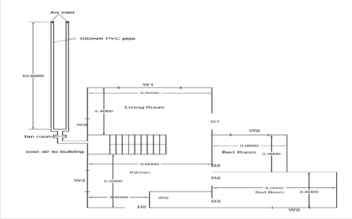
3. DESIGN FOR RESIDENTIAL BUILDING:-
1) Total area of building 815 sqft or 76sqmt
2) Volume of building 76 X 3.1=235Cubmt
3) Number of persons in building = 4
4) Direct Sunrays On South-West side per day= 5 hr/day
3.1 Design of Exhaust fan
Volume of building = 235Cubmt
As per thumb rule, take 20% of total volume
= 47cubmt or 1660 cubft
Assume 30 min for air change
CFM required = 1660/30 = 55 CFM Siracco CBR 04fan which has 58 CFM
So one fan requires for residential building
Plan of residential Building
International Journal of Scientific & Engineering Research, Volume 4, Issue 8, August-2013 1995
ISSN 2229-5518
Item no. | Description | Quantity | Rate | Amount |
1 | Escavation for pipe laying and fan room in hard murum including removal of excavated material up to 50m | 14 | Rs 100/cum | Rs 4000 |
2 | Brick wall for fan room | 0.48 cum | Rs- 3750/cum | Rs 500 |
3 | 110mm PVC pipe for earth tube | 20m | Rs 600/6m | Rs 2000 |
4 | 190mm PVC pipe for main pipe | 3m | Rs 1200/6m | Rs600 |
5 | 100 mm PVC bend in 90 degree | 2 no | RS-150/no | Rs-300 |
6 | Exhaust fan size-6” | 1 | Rs 1300 | Rs 1300 |
| | | TOTAL | Rs 8700 |
3.2 Details Of Other Parameters
Estimate of geothermal ventilation for residential building
Condensation or groundwater seepage can cause water to ac-
cumulate in the tubes exacerbating the problem. If the tubes
1) Deeper positioning of the tubes ensures better perfor- mance. Typical depths are 1.5 to 3 m. Depth of pipe be- low ground - 2m.
2) Length can typically range from 10 to 100 m. Longer tubes correspond to more effective systems. Length of one pipe - 10 m
3) Number of pipes – 2
4) Smaller diameters are preferred from a thermal point of
view, but they also correspond to higher friction losses.
Typical diameters are 10 cm to 30 cm. Diameter of pipe
– 100 mm
4. EXPERIMENTAL IMPLEMENTATION
4.1 Implementation Considerations
Earth cooling tubes will not perform well as a source of cooling unless the soil temperature is decidedly lower than the desired room air temperature. Tempering of outdoor air, how- ever, simply requires that the soil temperature surrounding the earth tubes be reasonably lower than the outdoor air tem- perature. Over the course of the cooling season, the soil sur- rounding earth tubes will warm up from its normal tempera- ture condition due to the transfer of heat from the tube to the soil. This tends to degrade performance over time during a cooling or warming season. Although condensation in earth tubes is possible, dehumidification of outdoor air is usually difficult and may require the use of mechanical dehumidifiers or passive desiccant systems.
A major concern with cooling tubes is that the tubes can become a breeding ground for mold, fungi, and/or bacteria.
cannot be easily monitored and/or cleaned it might be wise to
consider an indirect approach whereby cooling effect is trans-
ferred from “tube air” to another independent air stream prior
to entry into the building. This will, however, decrease system
capacity. Grilles and screens are advisable to keep insects and
rodents from entering occupied spaces from the exterior through the tubes.
4.2 Work done on site:-
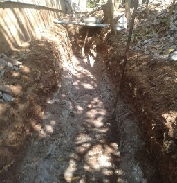
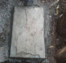
4.2.1 Excavation:-
Manually excavation has been done of size 1m wide, 10m in
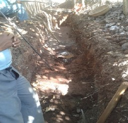
length and 1.2m deep as shown in Fig.1
IJSER © 2013 http://www.ijser.org
International Journal of Scientific & Engineering Research, Volume 4, Issue 8, August-2013 1996
ISSN 2229-5518
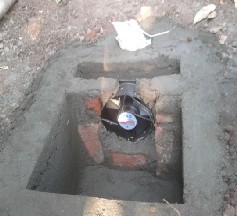
4.2.3 Construction of fan chamber :-
Fan room is constructed of size 60cm in length, 45cm in width and 22cm in height. Then fan is installed in the fan room of diameter 15cm and of CFM 78. Two pipes of diameter
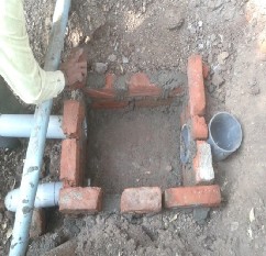
110mm are installed at inlet of fan room and a pipe of 150mm diameter installed at outlet of fan room. To avoid air loss top of fan room is covered by shahabadi tile of size 70 X 50 cm.
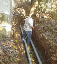
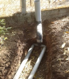
4.2.2 Placing of pipes:-
After excavation, pipes are placed of diameter 110mm
and length of 10m.
IJSER © 2013 http://www.ijser.org
International Journal of Scientific & Engineering Research, Volume 4, Issue 8, August-2013 1997
ISSN 2229-5518
4.2.4 Cool air outlet in building:-
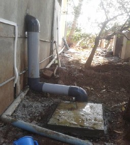
140mm PVC pipe inserted in the building one end is connected to fan room.
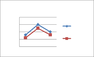
March 2013
40
35
30
25
20
20/03/2013
10am 2pm 5pm
Tem- pera- ture read-
ings on
19and
20
Ventilation system off
Ventilation system on

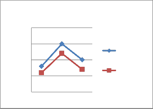
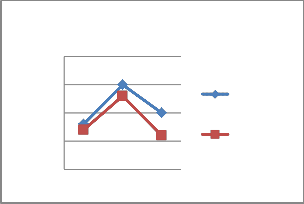
Temperature readings on 19and 21 march 2013
Temperature readings on 19and 21 march 2013
5. RESULTS
Temperature readings are taken on 19 March 2013 at that time ventilation system off and after that temperature readings are taken on 20,21,22, March 2013 during ventilation system on.
21/03/2013
40
35
30
25
Ventilation system off
Ventilation system on
IJSER © 2013 http://www.ijser.org
20
10am 2pm 5pm
International Journal of Scientific & Engineering Research, Volume 4, Issue 8, August-2013 1998
ISSN 2229-5518
8. The experimental data and calculations results indi- cate that geothermal ventilation system is an energy saving solution.
7 ACKNOWLEDGEMENTS
22/03/2013
40
35
30
25
20
10am 2pm 5pm
Ventilation system off
Ventilation system on
I must mention several individuals and organizations that were of enormous help in the development of this work. Pro- fessor Dr. Mr. A.C.Attar My supervisor, philosopher and per- sonality with a Midas touch encouraged me to carry this work. His continuous invaluable knowledgably guidance through- out the course of this study helped me to complete the work up to this stage and hope will continue in further research.
I also very thankful to Dr.Mrs.S.S.Kulkarni for their valuable sugg`estions, critical examination of work during the progress, I am indebted to them.
I am very thankful to Architect Mr.PramodChougule for giving his valuable time and suggestions for my project.
In addition, very energetic and competitive atmos- phere of the Civil Engineering Department had much to do with this work. I acknowledge with thanks to faculty, teaching and non-teaching staff of the department, Central library and Colleagues.
6 CONCLUSIONS
1. The parameters such as length, diameter, spacing, depth etc. have been studied.
2. The design for residential building in R.K.Nagar, Kolhapur and new library building in RIT Sakharale is done.
3. The Geothermal ventilation system is implemented in residential building in Kolhapur. For 235 cum only
12sq.m open space is used. By having open areas around building we can easily implement ventilation system. For implementation, we can use the regular labors. Special skills are not required.
4. After implementation of geothermal ventilation sys- tem in residential building, the energy use for cooling is reduced by 1.56 KWh per day and cost saving per month is Rs-327/- in summer days.
5. After implementation of geothermal ventilation sys- tem in residential building, the temperature inside the building is reduced by 1.62°C.
6. Reduction in temperature has increased the thermal comfort of the occupants with less use of electrical en- ergy.
7. Geothermal ventilation system is good option for conventional ventilation systems with one time in- vestment and less maintenance cost.
Isincerely thank to Dr.Mrs.S.S.Kulkarni,for support- ing me to do this work and I am very much obliged to her.
Last but not the least;M.G.Walemy father, S.M.Walemy mother, constantly supported me for this work in all aspects
8 REFERENCES
Journal Papers
[1] Vikas Bansal , Rohit Misra, Ghanshyam Das Agrawal,
Jyotirmay Mathur Performance analysis of earth–pipe–air heat
exchanger for summer cooling, Energy and Buildings 42 (2010)
645–648
[2] A. Khalil Zaki, Al-musaed Amjad, Asaad Almssad Cooling
by underground earth tubes” 2nd PALENC Conference and
28th AIVC Conference on Building Low Energy Cooling and
Advanced Ventilation Technologies in the 21st Century, Sep-
tember 2007, Crete island, Greece
Books
[1]Alison G.Kwok, AIA and Walter T. Grondzik,The Green
Studio Handbook .
Proceedings Papers
[1] goswami and k.m. biseli, Use of underground air tunnels
for heating and cooling agricultural and residential buildings.
By. university of Florida
[2] Girja Sharan Performance of Single Pass earth-Tube Heat
Exchanger: An Experimental Study by Indian Institute of
Management ,Ahmedabad and Ratan Jadhav
[3]Miroslaw Zukowski, Beata Sadowska,Assessment of the
cooling potential of an earth-tube heat exchanger in residential
buildings, Wieslaw Sarosiek environmental engineering The
IJSER © 2013 http://www.ijser.org
International Journal of Scientific & Engineering Research, Vo lume 4, Issue 8, August-2013
ISSN 2229-5518
1999
8th International Conference .May 19-20, 2011, ISBN 978-9955-
28-828-2
IJSER lb)2013
http://www.ijserorq