International Journal of Scientific & Research, Volume 5, Issue 5, May-2014
ISSN 2229-5518
882
Denoising of Complex Signals using Multi band
Complex Wavelets with Improved Thresholding
G.Chandraiah, Dr T.Sreenivasulu Reddy, and Prof G. Ramachandra Reddy
Abstract –– The dual-tree complex wavelet transform (DT-CWT) which utilizes two 2- band discrete wavelet transform (DWT) was recently extended to M- band. In this paper we provide a simple construction method for an M-band DT- CWT, with M = rd where r, d Z. In particular, we show how to extend a given r- band DT-CWT to an rd – band one. For convenience, the case where r = 2, d = 2 is considered. However, the scheme can be extended to general {r, d} pairs straightforwardly .There are so many methods to denoise complex noisy signals, but this paper proposes an improved threshold method (soft thresholding with improved thresholding rule) used with M-band DTCWT to Denise the complex signals. Finally, the results obtained using the proposed algorithm is compared with the 2-band DTCWT algorithm.
Index Terms –– Wavelets, complex wavelets, 2- band dual- tree, M-band dual tree, Hilbert transform pairs, thresholding, Improved thresholding method.
—————————— ——————————
I. INTRODUCTION
The discrete dual-tree complex wavelet transform (DT-CWT) [1] provide approximate shift- invariance and directionality. The DT-CWT achieves these properties by employing two discrete wavelet associated with second DWT is the Hilbert transform of the first. This scheme was extended to M-band orthonormal wavelet bases in [2], the transform in [2] employs two M-band discrete wavelet transforms where the wavelet associated with the two transforms from Hilbert transform pairs.
It is well known to extend a 2-channel perfect reconstruction (PR) filter bank (FB) into an M- channel PR FB using tree structured FB (with M = 2d). A tree- structured FB also allows one to extend a 2- band DWT into an M-band DWT; M-band wavelet
transforms of that type are often called wavelet packets [3].
This construction can be extended to other {r, d} values straightforwardly.
This paper is organized as follows. In section II, implementation of the 2-Band DTCWT based on complex wavelets is provided. In section III, the necessary and sufficient condition to implement 4- Band DTCWT is discussed. In section IV, the complex signal denoising methods and the proposed improved thresholding methods are discussed. In section V, experimental results are given. At last, section VI, gives some conclusions.
II. THE 2-Band DUAL-TREE CWT
The 2-Band dual tree CWT employs two real DWTs as shown in Figures 1(a) and 1(b); the first DWT gives the real part of the transform while the second DWT gives the imaginary part.
However, it is not previously known how to
Let h0 (n) , h1 (n)
denote the low pass, high pass filter
properly extend a 2- band DT-CWT (with M = rd). In particular, it will be shown how to obtain an FIR 4- band DT-CWT from an FIR 2-band DT-CWT).
pair for the upper synthesis FB and let g0 (n) ,
g1 (n) denote the low pass and high pass filter pair for the lower synthesis FB.
IJSER © 2014 http://www.ijser.org
International Journal of Scientific & Research, Volume 5, Issue 5, May-2014
ISSN 2229-5518
883
Where denotes a direct sum of the vector spaces. The 2- band dual complex wavelet transform asks for
a second set of approximation spaces '
and the
associated orthogonal wavelet spaces w' , such that the wavelets (t) and ' (t) form a Hilbert transform pair.
Similarly, the M-band wavelet transform employs approximation spaces vi satisfying.
' M 1
vi vi1 w i1 .... wi1
(3)
Fig 1(a) Analysis FB for the 2 band DT-CWT
The M-band DT-CWT is constructed [5,6] by finding
a second set of approximation spaces v '
and wavelet
spaces w' k
such that the associated wavelet
functions k (t) and ' k (t) from Hilbert transform
pairs, for
k {1,2,....M-1} . In the following, we will
demonstrate how to construct an rd -band DT- CWT given an r-band DT-CWT. For convenience we will concentrate on the {r = 2, d = 2} case, yielding a 4- band DT-CWT, but the procedure can be easily adapted to general {r, d} pairs.
Fig 1(b) Synthesis FB for the 2 band DT-CWT
The inverse of the dual-tree CWT is as simple as the forward transform. To invert the transform, the
Suppose we are given a 2-channel orthonormal filter bank { h(2) (n), h(2) (n) } and its associated scaling function ( 2) (t) and wavelet ( 2) (t) . Suppose we are also given a second 2- cannel filter
bank { ' (2) ' (2)
inverse of each of the two real DWTs are used to
h0 (n), h1
' ( 2)
(n) } and its associated scaling
' (2)
obtain two real signals. These two real signals are then
function
(t)
and wavelet
(t) , where
averaged to obtain the final output.
' (2) (t) is the Hilbert transform of ( 2) (t) , i.e.
To overcome the DWT disadvantages the filters in one
' (2) ()
j sgn() (2) ()
(4)
tree must provide delays that are half a sample
different (at each filter’s input rate) from those in the opposite tree [4].
Where ‘sgn’ denotes the signum function. That is, we are given a 2-band ‘dual-tree’ complex wavelet
transform where the complex wavelet
g0 (n) h0 (n 0.5)
g (t) H { h (t)}
(1)
(2) (t) j ' (2) (t) is analytical.
III. THE 4-Band DUAL-TREE CWT
It is well known that 2-band wavelet bases
Now we would like to construct a 4-band complex wavelet transform. To that end, suppose that
f (n), f (n)is another 2-channel orthonormal filter
employ approximation spaces
vi which can be 0 1
decomposed into a higher level approximation space
bank. We can then obtain a 4-channel orthonormal
filter bank. Our aim is to construct a second wavelet
vi 1 and a detail space
wi 1 as
packet transform so that the wavelets (associated with
vi vi1 wi1
(2)
IJSER © 2014 http://www.ijser.org
International Journal of Scientific & Research, Volume 5, Issue 5, May-2014
ISSN 2229-5518
884
the two wavelet transforms) from Hilbert transform
SUFFICIENCY CONDITIONS FOR THE 4-BAND DT-CWT
filter banks so that the associated wavelets form Hilbert transform pairs. The 4-band DT-CWT developed here satisfies these conditions.
+
2 h1(n)
2 f0(n)
+
2 f1(n)
2 0(n)
2 h0(n)
+
2
+
Where
H ' (e
j )
e jk ( ) H
(e j )
+
2 1(n)
2 f0(n)
+
2 0(n)
+
2
1.5
if 0, / 2
2 f1(n)
()
1.5
for 0, / 2
and
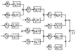
Fig 2 (b) Synthesis FB for the 4 band DT-CWT
() 0.5 0.5
k
for 0, , k 1, 2, 3
Thus, the new wavelets from Hilbert pairs if we set
These are exactly the sufficiency conditions
f ' (n)
f (n) for k {0,1}.Consequently, the dual of
for Hilbert transform pairs of wavelets for the 4-band case, provided in [6].
h0(n) 2
k k
the tree is obtained by simply replacing h (n) by h' (n) . This method generates a 4-band dual- tree complex wavelet transform. Here we are using q-
shift filters [7] of length 14 are used as
'
h0(n)
2
h1(n) 2
hk (n) and hk (n) ,
k {0,1}.
fk (n) is set equal to
hk (n) for
h1(n)
f0(n) 2
2
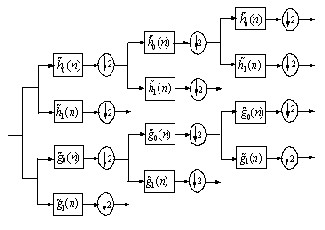
IV. SIGNAL DENOISING
f1(n) 2
Having a sampled noisy complex signal
N
0(n) 2
0(n) 2
s (s1, s2 ,...., sN ) C
given by
1(n) 2 f0(n) 2
sn f (xn ) zn n 1, 2,...., N
(5)
1(n) 2
Where the
zn z1n
iz2n
are identically and
f1(n) 2
Fig 2 (a) Analysis FB for the 4 band DT-CWT
independently distributed standard complex Gaussian
random variables. Their distribution is (z1n , z2n ) ' ~ Normal(0,1) .
We use the generalized hard thresholding
function to complex values as:
IJSER © 2014 http://www.ijser.org
wj ,
j
0,
 wj
wj 


wj
(6)
International Journal of Scientific & Research, Volume 5, Issue 5, May-2014
ISSN 2229-5518
885
The generalized soft thresholding function to complex values is:
thresholding could be regarded as a compromising between the hard- and soft- thresholding.
So the improved thresholding de-noising method presented in this paper could choose


sgn(w ) w
j
,


wj
(7)
appropriate β by trial-and-error to satisfy the request


0, wj
of de-noising.

Where is the threshold, ˆ 2 log N
is the
V. EXPERIMENTAL RESULTS
threshold. The robust estimate of the noise level ˆ on
In this paper, at first, the complex test signal is

is given by ˆ median wn n 1, 2,..., N
0.6745
are detail coefficients at the finest level
2 ; here w
generated by using two real test signals with “Heavy sine” signal as real part and ‘’Doppler signal’’ as imaginary part. This complex test signal is intercepted
A. .The Defects of Wavelet Thresholding Methods.
Hard and soft thresholding methods have got
better results in de-noising, but they also have some defects:
1) In the hard-thresholding case, the estimated wavelet coefficients wˆ are not continuous at position . It may lead to oscillation of the reconstructed signal.
2) In the soft-thresholding case, when  w
w , there are constant deviations between wˆ and w , which reduces the amplitudes of the reconstructed signal.
B. Improved Wavelet Thresholding Denoising Method
To overcome the defects of hard- and soft-
thresholding de-noising methods, an improved thresholding is defined in this paper as follows:
to be the original test signal. The length of the original test signal (i.e., the number of the sample points) is N = 512 (See Fig. 2(a)). Complex Gaussian white noise is added to the original test signal at random. So the noisy test signal with SNR of 10 dB is obtained and shown in Fig. 2(b). The test signal is processed using two different algorithms, respectively (1) Complex data is processed using traditional 2 band DT CWT and (2) Complex data processed using
4 band DT CWT.
For the both DT CWT algorithm Hilbert transform pairs of wavelet bases with 14 coefficients are used (generated with parameters K=4 and L=3). The both DT CWT are performed with hard- thresholding, soft-thresholding and improved thresholding respectively to denoise the noisy test signal. In the two algorithms with improved
w j


( w ( j w j ) ),


w
thresholding, the coefficient β is chosen as β =1.

j j j j
(8)
The denoised test signals by using the universal
DI (w) w j
0,


w j j
threshold selection with hard and soft thresholding along with the improved threshold de-noising with
Where
R and β > 1,
wj are the wavelet
three methods are shown in Fig. 2(a)-2(h).

coefficients at level j. Because of the magnitudes of the wavelet coefficients are related to the Gaussian white noise, decrease as the scale j increases, we chose
j

2 log N / log( j 1)
(9)
Equation (8) will be equivalent to hard- thresholding when β →∞ and will be equivalent to soft-thresholding when β→1. Therefore, the improved
IJSER © 2014 http://www.ijser.org
International Journal of Scientific & Research, Volume 5, Issue 5, May-2014
ISSN 2229-5518
886
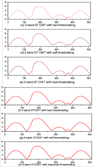
TABLE 1
SNR OF DENOISED TEST SIGNALS USING DIFFERENT DENOISING METHODS
Thresholding | Threshold selection rule | 2 band DT CWT | 4 band DT CWT |
Hard | Rigrsure | 22.03 | 23.23 |
Hard | Heursure | 22.21 | 23.28 |
Hard | Sqtwolog | 22.67 | 23.56 |
Hard | Minimaxi | 22.34 | 23.39 |
Soft | Rigrsure | 22.10 | 23.40 |
Soft | Heursre | 22.23 | 23.54 |
Soft | Sqtwolog | 22.92 | 23.66 |
Soft | Minimaxi | 22.98 | 23.87 |
Improved | Improved | 23.12 | 24.18 |
VI. CONCLUSION
Fig 2. Denoised test signals by using different de-noising methods
From Fig. 2(h), it is clear that the improved thresholding de-noising method using 4 band DT CWT is giving better results.
Table 1 gives the SNR of denoised signals by using different de-noising methods. It can be found that the denoised signal obtained using 4 band DT CWT has higher SNR than the 2 band DTCWT with the improved thresholding has the highest SNR among all methods and is more similar to the original test signal.
We have proposed an extension of existing works on Hilbert transform pairs of dyadic orthonormal wavelets to the M-band case. The 2 band DT CWT with the traditional thresholding methods and the 4 band DT CWT with the improved thresholding proposed in this paper are superior to other several traditional thresholding de-noising methods in many aspects, such as smoothness, remaining the geometrical characteristics of the original test signal. Although the coefficient β could be chosen flexibly, it must be chosen by trial-and- error according to the needs of practice. So it is valuable to study how to find appropriate coefficient β rapidly and exactly.
VII. ACKNOWLEDGMENT
We would like to thank Department of Science andTechnology (DST) for providing financial assistance and also National Atmospheric Research Laboratory (NARL),Gadanki for providing technical assistance.
IJSER © 2014 http://www.ijser.org
International Journal of Scientific & Research, Volume 5, Issue 5, May-2014
ISSN 2229-5518
887
REFERENCES
[1] Ivan.W. Selesnick, Richard G. Baranuik and N.G. Kingsbury, “The Dual-Tree Complex wavelet Transform,” IEEE Signal Processing Magazine, pp. 123–151, November
2005.
[2] I. Daubechies, “Orthonormal bases of compactly supported wavelets,” Commun. Pure Applied Math., vol. XLI, no. 41, pp.
909–996, Nov. 1988.
[3] S. Mallat. A Wavelet Tour of Signal Processing. Academic
Press, 1998.
[4] I.W. Selesnick, “Hilbert transform pairs of wavelet bases,”
IEEE Signal Processing Lett. vol. 8, no. 6, pp. 170–173, June
2001
[5] C. Chaux, L. Duval, and J.-C. Pesquet. Hilbert pairs of
M-band orthonormal wavelet bases. In Proc. Eur. Sig. and
Image Proc. Conf., 2004.
[6] C. Chaux, L. Duval, and J.-C. Pesquet. Image analysis using a dual-tree M-band wavelet transform. IEEE Trans. on Image Processing, 15(8):2397–2412, August 2006.
[7] N. G. Kingsbury. Design of q-shift complex wavelets for image processing using frequency domain energy minimization. In Proc. IEEE Int. Conf. on Image Processing (ICIP), 2003.

G. Chandraiah received the B.Tech degree in ECE from Jawaharlal Nehru Technological University in 2005 And M.Tech in Electronics Instrumentation and Communication Systems from Sri Venkateswara University College of Engineering, Tirupati in 2011.

T. Sreenivasulu Reddy received the B.Tech. Degree in ECE from Sri Venkateswara University, Tirupati, India, in 1990, the M.Eng. Degree in Digital Electronics from Karnatak University, Dharwad, India, in 1996 and Ph.D. degree in Radar Signal Processing
from Sri Venkateswara University, Tirupati. He is currently an Associate Professor with the Department of Electronics and Communication Engineering, College of Engineering, Sri Venkateswara University. His research interests include radar and image signal processing. Mr. Reddy is a Fellow of the
Institution of Electronics and Telecommunication Engineers and a member of the Indian Society for Technical Education.

G. Ramachandra Reddy received theM.Sc. and M.Sc.(Tech.) degrees from theBirla Institute of Technology and Science,Pilani, India, in 1973 and
1975,respectively, and the Ph.D. degree fromthe Indian Institute of
Technology,Madras, India, in 1987. In
1976, he joined the Department of Electrical and Electronics Engineering, ollege of Engineering, Sri Venkateswara University, Tirupati, India, and worked till 2010. He is currently Senior Professor in VIT University, Vellore. Also, he is holding the position of dean for the School of Electronics Engineering and Accreditation and Academic Committee. From February 1989 to May 1991, he was with the Department of Electrical and Computer Engineering, Concordia University, Montreal, QC, Canada, as a Visiting Scientist. Dr. Ramachandra Reddy is a Fellow of the Institution of Electronics and Telecommunication Engineers and a member of the Indian Society for Technical Education.
.
IJSER © 2014 http://www.ijser.org