International Journal of Scientific & Engineering Research, Volume 4, Issue 10, October-2013 560
ISSN 2229-5518
Digital Eye for Coach Guidance Automation
Syed Ahamed, M. Vijaya Kumar, V. Samson Deva Kumar
Abstract— This paper describes implementation of a system to get exact order of the coaches of the train approaching the station using the RFID Technology. In this system each coach is attached with an RFID Tag, which is read by the RFID reader placed at the outskirts of the station and after being detected, the data is sent by the RF Transmitter to the control room. Here, there will be no human interference in the transmission of data from station outskirts to the control room. In the station receiving module receives the data sent from the transmitter and then it is sent to the station master’s pc, where the actual platform is decided to display the order of the coaches using LCD displays. The system is implemented using AT89S52 microcontroller and Keil micro vision software’s.
Index Terms— RFID Tags, RF Reader, LCD, RF Transmitter, RF Receiver, Encoder, Decoder.
—————————— ——————————
1 INTRODUCTION
HE automation is playing an important role in every sector. But, in today’s railways the passengers are fac- ing a lot of problem in finding the exact coach number

which was already mentioned to them by the reservation department at the time of getting a reserved ticket. As a re- sult, of which sometimes they are missing their train that is due to the occurrence of irregular order of the coaches at station. In Indian railways when the train has left from one station to the other station, then a person from that station has to intimate the next station operator regarding the order of the coaches of the respective approaching train by mes- sage or call. Then the person from operator room intimates to a person in the control room and that person will moni- tors the coach number display on LCD screen which are pre- sent on the platform. This involves a lot of manual work and sometimes it may also get corrupted. So, in order to over- come this problem we have acquired an embedded technol- ogy [1] i.e., using the required RFID Technology for the pro- ject. To make this, manual process atomized we are using RFID passive tags, Radio-frequency identification (RFID) is the wireless non-contact radio system to transfer data from a tag attached to an object, for the purposes of identification and tracking [2] and [3].
2 DEGA SYSTEM
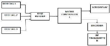
The DEGA system consists of two sections named as trans- mitter and receiver. The transmitter section is located in the outskirts of the station and the receiver is placed inside the station’s control room. Each coach in the train consists of an RFID tag attached to its number plate and RFID reader is attached to the signal post. Whenever the train passes to the signal point the RFID Tag on the coach will be detected and will be sent to the control room. Once all the coach numbers are sent then platform will be decided to display on the LCD displays placed on the platforms,[4].
inside the tag. That data is received by the reader by EM waves and sends to the microcontroller. Then controller identifies whether the tag (valid/invalid) is scanned and sends the related information to thes encoder as well as LCD display to display whether that card is valid or not. If valid card enters then it display’s the coach numbers in sequence order. If not it shows an “invalid card” message. If card is valid then related information is sends to the HT12E encoder by the microcontroller. Encoder is used to convert the paral- lel data to serial data. HT12E encoder has 4 data lines (pins
10, 11, 12, 13) and one Tx line (pin 17). The information is send through the RF transmitter. The RF transmitter has 4 lines (data, antenna, VCC , GND). The data from the encoder is connected to the data pin of RF transmitter and the infor- mation is transmitted through RF antenna to the RF receiver. Both the RF transmitter and receiver are tuned to the same frequency of 433MHZ. The additional block in transmitter is MAX232 is used at the initial stage to load the RF tag infor- mation. The MAX232 is used to convert the TTL voltage lev- els to PC voltage levels.
The various components in the block diagram are
AT89S52 Microcontroller
16x2 Liquid Crystal Display (LCD)
RFID Tag RFID Reader RF Module
HT12E Encoder
HT12D Decoder
2.1 Transmitter Section
The RFID reader is a device used to read the tag information. The reader has an antenna that emits radio waves, the tag responds by sending back its data, which is stored in a chip
IJSER © 2013 http://www.ijser.org
International Journal of Scientific & Engineering Research, Volume 4, Issue 10, October-2013 561
ISSN 2229-5518
Fig 1: Block Diagram of Transmitter Section
2.3 RFID System
An RFID system uses wireless radio communication tech- nology to uniquely identify tagged objects or people. There are three basic components to an RFID system are
1. A tag (sometimes called a transponder), which is com-
posed of a semiconductor Chip, an antenna, and sometimes a battery
2. An interrogator (sometimes called a Reader), which is composed of an antenna, an RF electronics module, and a control electronics module.
3. A controller (sometimes called a host), which most often takes the form of a PC or a workstation running database and control (often called middleware) software.
PASSIVE TAGS: Also called as ‘pure passive’ or ‘beam pow-
ered. Obtains operating power from reader. The reader
sends electromagnetic waves that induce current in the tags antenna, the tag reflects RF signal transmitted and adds in- formation by modulating reflected signal.
2.4 RFID Reader
An RFID interrogator acts as a bridge between the RFID tag and the controller. Read the data contents of an RFID tag. Write data to the tag (in the case of smart tags).Relay data to and from the controller. Power the tag (in the case of passive tags).Data encryption to protect the integrity of data.
2.5 RF Module

The RF module, as the name suggests, operates at Radio Frequency. The corresponding frequency range varies be- tween 30 kHz & 300 GHz. In this RF system, the digital data is represented as variations in the amplitude of carrier wave. This kind of modulation is known as Amplitude Shift Key- ing (ASK).Transmission through RF is better than IR (infra- red) because of many reasons. Firstly, signals through RF can travel through larger distances making it suitable for long range applications. Also, while IR mostly operates in line-of- sight mode, RF signals can travel even when there is an ob- struction between transmitter & receiver. Next, RF transmis- sion is more strong and reliable than IR transmission. RF communication uses a particular or specific frequency unlike IR signals which are affected by other IR emitting sources. This RF module comprises an RF Transmitter and an RF Re- ceiver. The transmitter/receiver (TX/Rx) pair operates at a frequency of 434 MHz RF transmitter receives serial data and transmits it wirelessly through RF. The transmission occurs at the rate of 1Kbps - 10Kbps.The transmitted data is received by an RF receiver operating at the same frequency as that of the transmitter.
2.6 HT12E Encoder
The HT 12E Encoder ICs are series of CMOS LSIs for Remote Control system applications. They are capable of Encoding information of 12 bits which consists of N address bits and
12-N data bits. Each address/data input is externally trinary
programmable if bonded out.
2.7 HT12D Decoder
The HT 12D ICs are series of CMOS LSIs for remote control system applications. These ICs are paired to each other. For proper operation a pair of encoder/decoder with the same number of address and data format should be selected. The Decoder receive the serial address and data from its corre- sponding decoder, transmitted by a carrier using an Re- transmission medium and gives output to the output pins after processing the data.
2.8 Receiver and Display Section
The RF receiver receives the information through the anten- na. The RF receiver consists of 8 lines. Here we are using 4 lines for required performance. The received data is in paral- lel form. So, we have a decoder HT12D is for converting the serial data to parallel form. There pin (pin no14) in HT12D is used to receive the data from RF receiver and the 4 data lines of decoder (pin no’s:10,11,12,13) are connected to the micro- controller. Here, the receiver consists of two AT89S52 micro- controllers. One microcontroller is considered as main mi- crocontroller and other one is used to drive the 3 LCDs. The main microcontroller is used to receive the parallel data from decoder. From the main micro-controller the data is stored into the personal computer in the control room and as well as to the other microcontroller to display the coach numbers individually on the LCD screens. The connection between two microcontrollers is established through a switch SW2. For resetting the content in the main microcon- troller, SW1 switch is used. When the valid information is received by main microcontroller then that data is simulta- neously transformed to the other microcontroller and also to the PC through MAX232 .The MAX232 is an integrated cir- cuit with 8 pins that convert signals from an RS-232serial port to signals suitable for use in TTL compatible digital log- ic circuits. To store the information in PC we are using HY- PER TERMINAL software program.
IJSER © 2013 http://www.ijser.org
International Journal of Scientific & Engineering Research, Volume 4, Issue 10, October-2013 562
ISSN 2229-5518
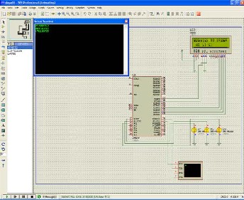
Proteus is used for microprocessor or micro controller simulation, schematic capture, and printed circuit board (PCB) design. In proteus, designing is done by collecting the components from the library. By drag and drop the components can be placed. The code is dumped into the controller and output is verified.
3.4 Schematic Diagrams
Fig 2: Receiver Section
3 IMPLEMENTATION
3.1 KEIL Software
Keil compiler is software used where the machine language code is written and compiled. After compilation, the machine source code is converted into hex code which is to be dumped into the microcontroller. It also supports C language code. It implemented the first C compiler designed from the ground up specifically for 8051 microcontroller. It provides broad range of development tools like ANSI C compiler, macro assembler, debuggers and simulators, linkers, IDE library managers, real time operating system & evaluation boards for 8051 &ARM families. [9]
3.2 Flash Magic Software
The flash magic software is one of the best known microcon- troller programs dumping software. It has the compatibility with the KEIL software. The HEX file generated by the KEIL is used by the FLASH MAGIC to program the microcontrol- ler. To dump the code program first the FLASH MAGIC has to be provided with necessary information about the target, the baud rate supported, the clock frequency, etc., and then the software checks for the device connected to the computer serial port. If the target is not connected, an error is generat- ed.
3.3 Proteus Software
Fig 3: Transmitter Module
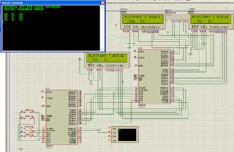
Fig 4: Receiver Module
4 MODULES FOR CODE DESIGN
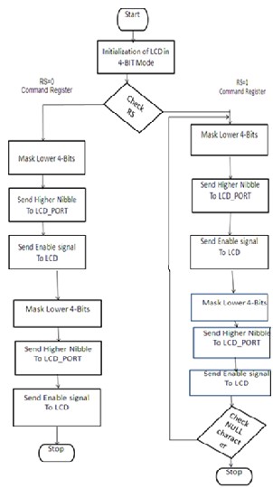
4.1 LCD Module
IJSER © 2013 http://www.ijser.org
Int 4, Issue 10, Octo
ISS

Fig 6: Flow Chart of the System
4.2 WORKING
Fig 5: Flow chart of the LCD Module
5 EXPERIMENTAL RESULTS
This paper gives a different way of approaching the prob- lem. The proposed system gives the exact display of the or- der of the coaches’ numbers in the LCD displays on the plat- form using the RF module for transmission and reception. By using the flow chart in figure 7, the source code is devel- oped. This source code is written in embedded C language
Whenever RFID Tags which are attached to the bogies are scanned for their unique ID by the RFID Reader at the signal post which is present at the outskirts of the station. Then the Reader checks whether the card scanned is valid or not. Once the card it is known as valid, it is transmitted to the controller from where they are transmitted using ASK mod- ulation technique and they are transmitted to the receiver section along with the display of the same data in a LCD display which is present in the Transmitter module. In the Receiver section, the data which is transmitted is received by the RF receiver and it is transmitted to the Micro controller (master), which is connected to the PC of the Station master. The whole order of the coaches of the train can be displayed on the PC, by which station master decides to select the re- spective platform using the switches which are present to select. Once the platform is selected, the controller (master) commands the slave controller to display the data in the LCD displays placed in the respective platforms. Then the order of the coaches can be displayed in the LCD displays of the platforms in the station.
and is tested on Proteus 7.2 platform. The hardware imple-
mentation of the Digital eye for coach guidance automation
is shown in figures.
IJSER © 2013 http://www.ijser.org
International Journal of Scientific & Engineering Research, Volume 4, Issue 10, October-2013 564
ISSN 2229-5518
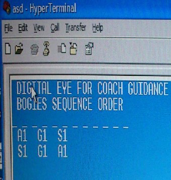
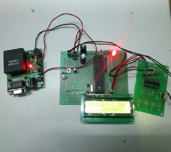
Fig 7: Transmitter Section
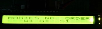
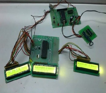
Fig 8: Transmitter Section with the display of the order of the coaches
Fig 10: Output Sequence of the bogies in the Hyper Terminal of the PC
of Station Master
Fig 9: Receiving Section
6 CONCLUSION
To reduce the manual process, we are using RFID passive tags, since Radio-frequency identification (RFID) is the use of a wireless non-contact radio system to transfer data from a tag attached to an object, for the purposes of identification and tracking. Thus the RFID plays a major part of operation for coach number display without any manuals work in railways. Thus the errors are reduced which occur while displaying the coach numbers. Since it is a demonstration unit, the frequency of RF antenna and Tag is limited to
434MHz. Because, in this project work a low power transmit-
ter is used and the limitation being the power transmitted by
the RF antenna. The proposed design can track the RFID signals within 2m range. However by increasing the power radiating capacity of the antenna the range can be increased and by using parallel readers tracking of the RF card is also possible.
ACKNOWLEDGMENT
I would like to thank our HOD sir- Dr. M. Kamaraju, M. Vi- jaya Kumar Sir-Assistant Professor, ECE Department, Gud- lavalleru Engineering College, Gudlavalleru. I also express my grateful thanks to principal-Dr. P. Nageswar Reddy; Gudlavalleru Engineering College. I would also like to thank Mr. V. Samson Deva Kumar, project manager, SCR.
IJSER © 2013 http://www.ijser.org
International Journal of Scientific & Engineering Research, Volume 4, Issue 10, October-2013 565
ISSN 2229-5518
REFERENCES
[1] Muhammad Naveed, WasimHabib, UsmanMasud, UbaidUllah, and Gulzar:”Reliable and Low Cost RFID Based Authentication System for Large Scale Deployment” International Journal of Network Se- curity, Vol.14, No.3,PP. 173{179, May 2012.
[2] Greg Goth:”RFID: Not Quite Prime Time, But Daw-
dle at Your Own Risk” IEEE DISTRIBUTED SYS- TEMS ONLINE 1541-4922 © 2005 Published by the IEEE Computer Society, Vol. 6, No. 2; 2005.
[3] Dhanalakshmi M, Uppala Mamatha:” RFID Based Library Management System “Proceedings of ASCNT – 2009, CDAC, Noida, India, pp. 227 – 234.
[4] V.SRIDHAR:”AUTOMATEDSYSTEM DESIGN FOR
METRO TRAIN” International Journal of Computer
Science Engineering (IJCSE), ISSN: 2319-7323Vol. 1
No.01 September 2012
[5] M.A.Mazdi “The 8051 Micro Controllers and Em- bedded Systems” Pearson Education, Asia, 2nd Edi- tion, India 2008
[6] http://www.ipic.co.jp/Pdffiles/ht12e.pdf
[7] https://courses.cit.cornell.edu/ee476/FinalProjects/s2
008/cl457_yft2/cl457_yft2/datasheets/HT12D.pdf [8] www.keil.com/dd/docs/datashts/atmelAT89S52 [9] http://www.keil.com/product/brochures/uv3.pdf
[10] http://www.atmel.com
IJSER © 2013 http://www.ijser.org