transmitted by the AOTF [7] can be express as:
International Journal of Scientific & Engineering Research, Volume 4, Issue 6, June 2013
ISSN 2229-5518 1482
Crosstalk Analysis of an Acousto-Optic Tunable Filter Based Optical Add/Drop Multiplexer for DWDM System
Md. Saiduzzaman, Imtiaz Ahmed, Kowshik Mushfiq-ur-Rahman
Abstract— Dense Wavelength Division Multiplexing (DW DM) system is limited by different impairments like optical attenuation, crosstalk, chromatic dispersion, polarization mode dispersion, Scattering etc. All of these impairments restrict the transmission distance and bandwidth. In the Present Scenario the DW DM system needs significant improvement, where analyzing the crosstalk of an Acousto-Optic Tunable Filter (AOTF) based Optical Add/Drop Multiplexer (OADM). This paper conducts a comprehensive study of DW DM system and extracts the optimum performance of the overall system by increasing the channel spacing of the AOTF with a significant improvement of signal to crosstalk ratio with channel spacing and reduced bit error rate as the bandwidth of the channel is increased accordingly.
Index Terms— Acousto-Optic Tunable Filter (AOTF), Bit Error Rate (BER), Crosstalk, Dense Wavelength Division Multiplexing (DW DM), Optical Add/Drop Multiplexer (OADM), Optical cross connect (OXC), Signal to Crosstalk Ratio (SCR), Wavelength Division Multiplex- ing (W DM)
—————————— ——————————
he popularity of Dense Wavelength Division Multiplexing (DWDM) is increasing extensively for long-haul optical communication due to its high cost effectiveness. Closely spaced channels within the same window makes the system easy to manage and provides increased flexibility, but the re- quirement of very narrow spectral-width laser sources, this technique also needs very low loss optical add/drop multi- plexer (OADM) with minimum fluctuations. Acousto-Optic Tunable Filter (AOTF) is a potential solution to this problem. Several papers have been published in the area of An OADM design based on fiber Bragg gratings [1], Interferometric cross talk-free OADM using cascaded Mach-Zehnder fiber gratings [2]. But most of these researchers have focused their work from the optical signal processing point of view and not from tunable MUX/DEMUX aspect, especially using acousto-optic concept. However several authors have discussed about acousto-optic wavelength tunable switches and filters (AOTF) but as a simple OADM with limited tenability. In this paper the basic concept and thorough analysis of an acousto-optic tunable filter based OADM system has been presented, where we simulated the filter transfer function from a very narrow channel spacing of 0.1nm up to as wide as 1nm, which shows a significant improvement of SCNR. Result also shows that increasing the bandwidth within the cost effective range of
10GHz to 250GHz causes a significant improvement in BER.
————————————————
• Md. Saiduzzaman has completed Bachelor degree program in Electrical and
Electronic Engineering, Dhaka, Bangladesh. Email: sonetshah@yahoo.com
• Imtiaz Ahmed has completed Bachelor degree program in Electrical and
Electronic Engineering, Dhaka, Bangladesh.
Email: imtiaz.ahmed_m@yahoo.com
• Kowshik Mushfiq-ur-Rahman has completed Bachelor degree program in
Electrical and Electronic Engineering, Dhaka, Bangladesh.
The main function of an optical multiplexer is to couple two or more wavelengths into the same fiber. If a demultiplexer is placed and properly aligned back-to-back with a multiplexer, it is clear that in the area between them, two individual wave- lengths exist.
This presents an opportunity for an enhanced function, one in which individual wavelengths could be removed and also inserted. Such a function would be called an optical wave- length drop and add demultiplexer/multiplexer-and for brev- ity, optical add/drop multiplexer. OADM is still evolving, and although these components are relatively small, in the future, integration will play a key role in producing compact, mono- lithic and cost-effective devices [3].
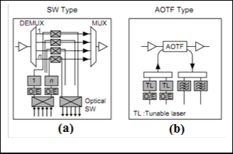
Regarding the architecture of dynamic OADM configurations, there are two types [4]. One is the SW type with a back-to-back multiplexer/ demultiplexer, and the other is the AOTF type. Figure 1 shows these configurations. One of the technical diffi- culties in using the SW type for OADM is that for limited channels in a WDM system, a non optical switch will be re- quired on the drop and add sides to accomplish a dynamic capability. This can be extremely expensive and cumbersome. Other problems such as channel passband narrowing due to concatenation of multiplexers/demultiplexers for a channel spacing of 0.8 nm or less can also create major problems in a long-distance network. The AOTF type holds a lot of promise for providing a cost-effective solution for a static as well as dynamic OADM and presents no passband narrowing prob-
IJSER © 2013 http://www.ijser.org
The research paper published by IJSER journal is about Crosstalk Analysis of an Acousto-Optic Tunable Filter Based Optical Add/Drop Multiplexer for DWDM System
ISSN 2229-5518 1483
lem. We have therefore been developing dynamic OADM sys- tems using AOTF.![]()
transmitted by the AOTF [7] can be express as:
sin 2 ((Π / 2) 1 + (2∆λ / ∆)2
T (λ) =
Here
1 + (2∆λ / ∆)2
(1)
∆λ = λ − λ0
∆ = λ2 / 1* ∆n
(2)
(3)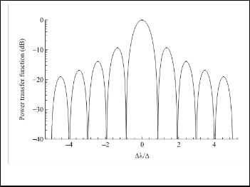
Fig.1: Shows the device configuration of SW and AOTF [5]
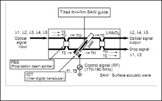
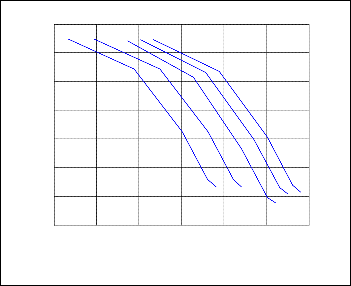
Fig.3: The Power Transfer Function of AOTF
Fig.2: Configuration of AOTF [5].
The Ratio between signal power and Crosstalk crosstalk pow- er is called signal to Crosstalk Ratio (SCR).
The acousto-optic tunable filter is a versatile device. It is prob- ably the only known tunable filter that is capable of selecting
SCR = ∑ Psig / ∑ PC
(4)
several wavelengths simultaneously. This capability can be used to construct an optical cross connect (OXC).
The theory is based on utilizing diffraction of light by the
The Ratio between signal power and to Crosstalk crosstalk power with noise power is called signal to Crosstalk Noise Ratio (SCNR).
refractive index gratings generated by the acoustic waves. The
SCNR = P
/ P + P
acoustic source which is usually an inter-digital transducer is
Sig c N
electronically controlled leading to an electronically tunable
= P / δ2
+ δ2
(5)
filter. An oscillating electric signal drives the transducer to vibrate, which creates sound waves in the glass. These can be
δ2 = δ2
sig C N
+ δ2
(6)
thought of as moving periodic planes of expansion and com-
N Shot Thermal
pression that change the index of refraction. Incoming light scatters off the resulting periodic index modulation and inter- ference occurs similar to in Bragg diffraction.
Changing the driving acoustic frequency changes the band
2
Shot
= Shot Noise
= 2eB(Rd * PSig )
(7)
of optical frequencies that the filter passes (selects). Changing the power of the acoustic wave changes the length required for complete diffraction of the input wave [6], [7].
The wavelength dependence of the fraction of the power
Rd = ηe / hf
= ηeλ0 / hc
δ2 = Thermal Noise = 4kTB / R
P = δ2 = Crosstalk Power
(8) (9)
IJSER © 2013 PSig =
The research paper published by IJSER journal is about Crosstalk Analysis of an Acousto-Optic Tunable Filter Based Optical Add/Drop Multiplexer for DWDM System
ISSN 2229-5518 1484
Signal Power
P = δ2 =
Noise Power
Here parameters have their usual meanings.
The bit error rate or bit error ratio (BER) is the number of bit errors divided by the total number of transferred bits during a studied time interval. BER is a unit less performance measure, often expressed as a percentage. The expression [8] can be ex- press as,
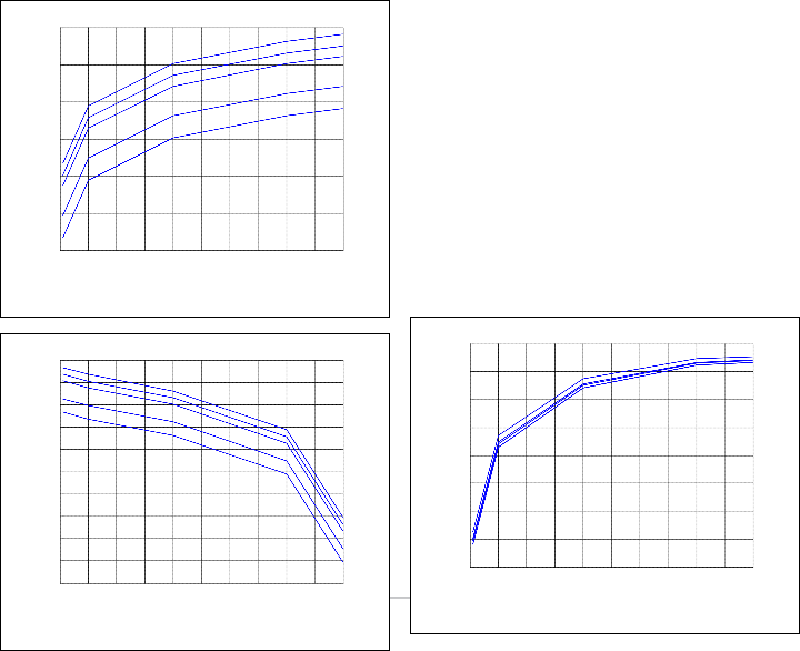
Plot of Crosstalk Power vs. Wave length Separation (∆λ) is shown in Fig. 5. From the fig, it is evident that the increase of
∆λ in the transmission line, Crosstalk Power decreases.
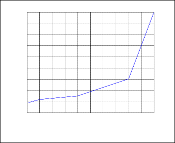
Plot of Signal to Crosstalk Ratio vs. Wave length Separation
(∆λ) is shown in Fig. 6. From the fig, it is evident that the in-![]()
BER = 1 erfc[
![]()
SCNR ]
(10)
crease of ∆λ in the transmission line, the SCR performance gets
2 2 2
Following the analytical approach presented in section 5, the Signal power, Cross-talk power, Signal to Crosstalk Ratio, Sig- nal to Crosstalk -Noise Ratio, Bit Rate Error and Power penal- ty results are evaluated
Plot of Signal Power vs. Wave length Separation (∆λ) is shown in Fig. 4. From the fig, it is evident that the increase of ∆λ in the transmission line, Signal Power increases.
better. That means the more we use spacing the more we get
SCR.
22
20
18
16
14
12
-60
10
-65 8
-70
6
4
0 0.1 0.2 0.3 0.4 0.5 0.6 0.7 0.8 0.9 1
-75
Wave Length Separation (m)
x 10
-10
-80
Fig.6: Signal to Crosstalk Ratio vs. Wave length Separation
-85
-90
0 0.1 0.2 0.3 0.4 0.5 0.6 0.7 0.8 0.9 1
Plot of Signal to Crosstalk Noise Ratio vs. Wave length Separa- tion (∆λ) is shown in Fig. 7. From the fig, it is evident that the increase of ∆λ in the transmission line, the SCNR performance gets better. That means the more we use spacing the more we
Wave Length Separation (m)
Fig.4: Signal Power vs. Wave length Separation
x 10
-10
get SCNR.
10
-65
5
-70
-75 0
-80 -5
-85
-90
-95
-100
-10
-15
-20
-105
-25
-110
-30
0 0.1 0.2 0.3 0.4 0.5 0.6 0.7 0.8 0.9 1
-115
0 0.1 0.2 0.3 0.4 0.5 0.6 0.7 0.8 0.9 1
R ©
Wave Length Separation (m)
x 10
-10
Wave Length Separation (m)
Fig.5: Crosstalk Power vs. Wave length Separation
x 10
-10
Fig.7: Signal to Crosstalk Noise Ratio vs. Wave length Separation
The research paper published by IJSER journal is about Crosstalk Analysis of an Acousto-Optic Tunable Filter Based Optical Add/Drop Multiplexer for DWDM System
ISSN 2229-5518 1485
TABLE 1
ASSUMPTION PARAMETERS
Plot of Bit Error Rate vs. Signal Power is shown in Fig. 8. From the fig, it is evident that the increase of Signal Power in the transmission line, Bit Error Rate decreases. That means we get more accurate data transmission through optical link. Also from the fig, we see that BER is decreasing with the increase of received power.
The Assumption parameters are as shown in Table 1
0
10
-2
10
-4
10
10-6 7 CONCLUSION
-8 OADM is essential part of DWDM system and for narrower
10
-10
10
-12
10
-14
10
-90 -85 -80 -75 -70 -65 -60
signalPower (dBm)
Fig.8: Bit Error Rate vs. Signal Power
Plot of Power Penalty vs. Wave length Separation (∆λ) is shown in Fig. 9. From the fig, it is observed that the increase of
∆λ in the transmission line, Signal Power decreases at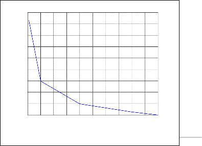
BER=10-9.
-3
x 10
10
9
8
7
6
5
4
3
2
channel spacing we use AOTF in the OADM instead of SW. But the main drawback in Acousto-Optic tunable Filter is the sec- ondary maxima (sidelobes) in its optical transmission spec- trum. This results in interchannel crosstalk in dense WDM systems which may lead to a bit error rate (BER) penalty. In this paper we are making sure that a narrow bandwidth was achieved and the sidelobe suppressed as far as possible. The sidelobes are suppressed by using optimum value of passband width.
Through the analysis we determined the performance of an Acousto-Optic Tunable Filter (AOTF) based optical add/drop multiplexer for DWDM system for different parameter values. We found that BER decrease with the increase of SCNR. Thus, from that figures, we can determine the value of BER for any giv- en SCNR. Now we can easily find out the received power, SCNR, input power, penalty power of a DWDM system. This will cer- tainly help us to designing a DWDM system.
AOTF - Acousto-Optic Tunable Filter
BER - Bit Error Rate
DWDM - Dense Wavelength Division Multiplexing
OADM - Optical Add/Drop Multiplexer
OXC - optical cross connect
SCR - Signal to Crosstalk Ratio
SCNR - Signal to Crosstalk Noise Ratio
WDM - Wavelength Division Multiplexing
1
0 0.1 0.2 0.3 0.4 0.5 0.6 0.7 0.8 0.9 1
Wave Length Separation (m)
Fig.9: Power Penalty vs. Wave length Separation
x 10
-10
The research paper published by IJSER journal is about Crosstalk Analysis of an Acousto-Optic Tunable Filter Based Optical Add/Drop Multiplexer for DWDM System
ISSN 2229-5518 1486
[1] Xuefang Zhou, Gongquan Liang, and Tianshu Wang, “An optical add-drop multiplexer design based on fiber Bragg gratings”, Elec- tronics and Optoelectronics (ICEOE), 29-31 July, 2011
[2] Mlzuochi T., and Kitayama T., “Interferometric cross talk-free optical add/drop multiplexer using cascaded Mach-Zehnder fiber gratings”, Optical Fiber Communication (OFC), 16-21 February, 1997
[3] Stamatios V. Kartalopoulos, “Introduction to DWDM technology:
data in a rainbow”, IEEE Press, NY, 1999
[4] Terumi Chikama, Hiroshi onaka, and Satoshi Kuroyanagi, “Photonic Networking Using Optical Drop Multiplexers and Optical Cross- Connects”, Fujitsu Sci. Tech. Journal, Vol. 35, no. 1, pp. 46-55, July,
1999
[5] T. Nakazawa, M. Doi, S.Taniguchi, Y. Takasu, and M. Seino, “Ti: LiNbO3 AOTF for 0.8nm Channel-Spaced WDM”, Optical Fiber Com- munication Conference, 22 February, 1998
[6] Jaafar M.H Elmirghani, “Technologies and Architectures for Scalable Dynamic Dense WDM Networks”, IEEE Communication Magazine, pp.58, February 2000
[7] Rajiv Ramaswami, Kumar N. Sivarajan, and Galen H. Sasaki, “Opti- cal-Networks”, 3rd Edition, pp.149-151, 2010
[8] John M. Senior, “Optical Fiber Communication”, 3rd Edition, pp.719,
2010-2011
IJSER © 2013 http://www.ijser.org