International Journal of Scientific & Engineering Research, Volume 4, Issue 6, June-2013 1081
ISSN 2229-5518
Construction of Solar Power Generating System through Free Space Satellites using Sputtering Technique-A Review Article
G S Ajay Kumar Reddy1, G Keerthy1*, D Sushma1*, U Ganag Raju2, V Manhar2, Ch Tarun2*, A Sai Ram2*, S Dileep Kumar2#
Abstract— This is a proposal for solar power generation in which the solar power is converted into microwaves through satellites called Solar Power Satellites (SPS) and it is received using a special type of antennae called rectenna, mounted on earth surface. The concept of free spac e power propagation is not a new concept and it is the topic of discussion for nearly four decades. In this paper we explain the same for the generation and reception of electrical power using the rectennas. Rectennas are special type of antennae that could convert the incoming microwave radiation into electricity and this electricity can be sent to grids for storage and future usage. The paper first discusses about the history of free space power transmission and gives a brief introduction to the rectenna concept. The important component of the rectenna, the schottky barrier diode is explained. Then the functional model for the Solar Power Satellite is explained. The importance of the solar energy is explained both in terms of the cost and its echo friendly nature. The paper is concluded explaining our model of a simple rectenna, which could be readily built using the components from the laboratory.
Keywords— Solar energy, Rectenna, Space Power Satellites, Schottky Diode, Spacetenna, Barrier, Micro W aves
—————————— ——————————
I. INTRODUCTION
Can’t we use solar power at the night? This question may look somewhat absurd since there is obviously no meaning of “Using solar power at night”! Now-a-days we are using the solar power to generate electricity by the solar panels mounted on the earth. But, in outer space, the sun always shines brightly. No clouds block the solar rays, and there is no night time. Solar collectors mounted on an orbiting satellite would thus generate power 24 hours per day, 365 days per year. If this power could be relayed to earth, then the world's energy problems might be solved forever.
The post-war history of research on free-space power transmission is well documented by William C. Brown, who was a pioneer of practical microwave power transmission. It was he who first succeeded in demonstrating a microwave powered helicopter in 1964. A power conversion device from microwave to DC, called a rectenna, was invented and used for the microwave- powered helicopter. The first rectenna was composed of 28 half-wave dipoles terminated in a bridge rectifier using point-contact semiconductor diodes. Later, the point contact semiconductor diodes were replaced by silicon Schottky-barrier diodes, which raised the microwave-to-DC conversion efficiency from 40 % to 84 %. The highest record of 84 % efficiency was attained in the demonstration of microwave power transmission in 1975 at the JPL Goldstone Facility. Power was successfully transferred from the transmitting large parabolic antenna dish to the distant rectenna site over a distance of 1.6 km. The DC
output was 30 kW. An important milestone in the history of microwave power transmission was the three year study program called the DOE/ NASA Satellite Power System Concept Development and Evaluation Program, started in
1977. The extensive study of the SPS ended in 1980, producing a 670 page summary document. The concept of the SPS was first proposed by P. E. Glaser in 1968 to meet both space-based and earth-based power needs. The SPS will generate electric power of the order of several hundreds to thousands of megawatts using photovoltaic cells of sizable area, and will transmit the generated power via a microwave beam to the receiving rectenna site. Among many technological key issues, which must be overcome before the SPS realization, microwave power transmission (MPT) is one of the most important key research issues. The problem contains not only the technological development microwave of power transmission with high efficiency and high safety, but also scientific analysis of microwave impact onto the space plasma environment.
II. RECTENNA
Rectenna is an acronym for RECTifying anTENNA. It is a special type of antenna that rectifies the incoming microwave radiation into DC current and hence the name Rectenna.
A rectenna comprises of a mesh of dipoles and diodes for absorbing microwave energy from a transmitter and converting it into electric power. Its elements are usually
IJSER © 2013 http://www.ijser.org
International Journal of Scientific & Engineering Research, Volume 4, Issue 6, June-2013 1082
ISSN 2229-5518
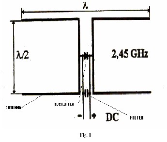
arranged in a mesh pattern, giving it a distinct appearance from most antennae. A simple rectenna can be constructed from a schottky diode placed between antenna dipoles as shown in Figure. 1. The diode rectifies the current induced in the antenna by the microwaves. Rectennae are highly efficient at converting microwave energy to electricity. In laboratory environments, efficiencies above 90% have been observed with regularity. In future rectennas will be used to generate large-scale power from microwave beams delivered from orbiting SPS satellites.
III. BRIEF INTRODUCTION OF SCHOTTKY BARRIER DIODE
A Schottky barrier diode is different from a common P/N silicon diode. The common diode is formed by connecting a P type semiconductor with an N type semiconductor, this is connecting between a semiconductor and another semiconductor; however, a Schottky barrier diode is formed by connecting a metal with a semiconductor. When the metal contacts the semiconductor, there will be a layer of potential barrier (Schottky barrier) formed on the contact surface of them, which shows a characteristic of rectification. The material of the semiconductor usually is a semiconductor of n-type (occasionally p-type), and the material of metal generally is chosen from different metals such as molybdenum, chromium, platinum and tungsten. Sputtering technique connects the metal and the semiconductor.
A Schottky barrier diode is a majority carrier device, while a common diode is a minority carrier device. When a common PN diode is turned from electric connecting to circuit breakage, the redundant minority carrier on the contact surface should be removed to result in time delay. The Schottky barrier diode itself has no minority carrier, it
can quickly turn from electric connecting to circuit breakage, its speed is much faster than a common P/N diode, so its reverse recovery time Trr is very short and shorter than 10 nS. And the forward voltage bias of the Schottky barrier diode is under 0.6V or so, lower than that (about 1.1V) of the common PN diode. So, The Schottky barrier diode is a comparatively ideal diode, such as for a 1 ampere limited current PN interface. Below is the comparison of power consumption between a common diode and a Schottky barrier diode:
P=0.6*1=0.6W P=1.1*1=1.1W
It appears that the standards of efficiency differ widely. Besides, the PIV of the Schottky barrier diode is generally far smaller than that of the PN diode; on the basis of the same unit, the PIV of the Schottky barrier diode is probably
50V while the PIV of the PN diode may be as high as 150V.
Another advantage of the Schottky barrier diode is a very low noise index that is very important for a communication receiver; its working scope may reach 20 GHz.
IV. DEVELOPMENT OF A FUNCTIONAL SYSTEM MODEL OF THE SOLAR POWER SATELLITE, SPS2000
SPS2000 is a straw man model of solar power satellites with microwave power output of 10 MW, which was proposed by the SPS working group of the Institute of Space and astronautically Science (ISAS). The primary objective of SPS2000 research is to show whether SPS could be realized with the present technology and to find out technical problems.
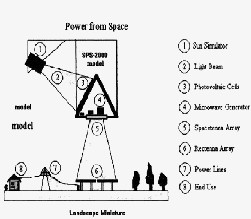
Figure.2: The general configuration of SPS2000
IJSER © 2013 http://www.ijser.org
International Journal of Scientific & Engineering Research, Volume 4, Issue 6, June-2013 1083
ISSN 2229-5518
The general configuration of SPS2000 has the shape like a triangular prism as shown in Figure 2. The prism axis
is in the latitudinal direction, perpendicular to the direction
of orbital motion. The power transmission antenna, spacetenna, is built on the bottom surface facing to the earth, and the other two surfaces are used to deploy the solar panels. SPS2000 moves on an equatorial LEO at an altitude of 1100km. The choice of the orbit minimizes the transportation cost and the distance of power transmission from space. The spacetenna is constructed as a phased- array antenna. It directs a microwave power beam to the position where a pilot signal is transmitted from a ground- based segment of power system, the rectenna. Therefore, the spacetenna has to be a huge phased-array antenna in size with a retro directive beam control capability.
So, microwave circuits are connected to each antenna element and driven by DC power generated in the huge solar panels. A frequency of 2.45 GHz is assigned to transmit power to the earth. Figure 2 also shows a scheme of microwave beam control and rectenna location. SPS2000 can serve exclusively the equatorial zone, especially benefiting geographically isolated lands in developing nations.
The Spacetenna has a square shape whose dimension is
132 meters by 132 meters and which is regularly filled with
1936 segments of sub array. The sub array is considered to be a unit of phase control and also a square shape whose edges are 3 meters. It contains 1320 units of cavity-backed slot antenna element and DC-RF circuit. Therefore, there will be about 2.6 million antenna elements in the spacetenna. Moreover, the pilot signal frequency and a frequency for the energy transmission are different from each other. Using two kinds of frequency for the power transmission and the pilot signal prevents each other from interfering and makes it possible to find out the accurate direction of a specified rectenna.
The Figure 4 illustrates a block diagram of the spacetenna. The spacetenna is composed of pilot signal receiving antennas followed by detectors finding out the location of the rectenna on the earth, power transmission antenna elements and phase control systems. The left and right hand sides in Fig.4 correspond to parts of power transmission and direction detection, respectively. The antenna elements receiving the pilot signal have a polarization perpendicular to the antenna elements used in the power transmission so as to reduce effectively interactions between both antenna elements.
V. SOLAR ENERGY-A LIMITLESS SOURCE OF ENERGY
The solar energy that reaches the Earth is about 10,000 time’s total human energy Production today and the energy available in near-Earth space is limitless. Research is being done on many different ways of using solar power economically on Earth, and many of these will be successful. Terrestrial solar energy is going to become a colossal business. However, sunlight is diffuse and not available continuously at the Earth's surface. So one additional possibility is to collect solar energy 24 hours per day in space, and transmit it as microwave beams to receivers on Earth. Compared to solar power collected at the Earth's surface, SPS faces the extra costs of space transportation and microwave power transmission.
But in order to supply continuous electric power, solar systems on Earth need much greater area for collection, large scale energy storage for supply during the night-time and when it's cloudy, and long-distance transmission from desert areas to population centres. Consequently, at the present state of knowledge we do not know that in future solar power from space could not compete with solar power collected on Earth. And so we believe that more research should be done on this possibility - and that SPS research should receive funding similar to other potential new energy sources. We support research efforts aimed at increasing the efficiency of energy use. But we also support efforts to demonstrate new, environmentally benign energy sources.
IJSER © 2013 http://www.ijser.org
International Journal of Scientific & Engineering Research, Volume 4, Issue 6, June-2013 1084
ISSN 2229-5518
VI. A MODEL OF RECTENNA
A simple rectenna that is helpful in understanding the principle is shown below:
Figure 5. A Typical Rectenna
Its operation follows: When the microwave source is turned ON, the electrons in the antenna are excited and they are made to oscillate at a frequency that is equal to the frequency of the microwave source. With this gained energy, the electrons pass through the schottky diode and due to the property of the diode; it will not allow the electrons in the reverse direction. So electrons accumulated at the other end of the diode should pass through the LED connected. In the practical rectenna circuits the LED is substituted by the path to the grid to store the electrical energy generated.
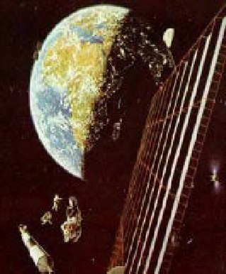
VII. MODEL FOR THE WHOLE SYSTEM
A Solar Power Satellite (SPS) with a thoroughly energized Earth in the background. One of the first things we will begin doing once we are using space resources is constructing a SPS, a vast solar array which gathers the constant solar power in orbit and beams energy to Earth in the form of a safe, low-density microwave beam. On Earth, the beam is intercepted by a rectenna several miles across, where it is converted back into electricity. The electricity is then rectified to AC, and fed into the power grid. This is shown in Figure 6. The goal is to generate undersell power by fossil fuels or nuclear energy.
The rectennas will be huge, but the land underneath need not go to waste. Since the array absorbs the microwaves, but allows sunlight and rainfall through, the land could be used for farming or ranching. Or, as in this case, the rectenna could be built as a vast set of greenhouses, feeding millions. This can be used for harvesting purposes also and establishing a green house system with millions of rectennas of schematically diagram of represented clearly in figure 7 and figure 8 below.

Figure 6: Reception by Rectenna
Figure 7: A Farm field with A Rectenna
IJSER © 2013 http://www.ijser.org
International Journal of Scientific & Engineering Research, Volume 4, Issue 6, June-2013 1085

ISSN 2229-5518
VI. ACKNOWLEDGEMENT
The authors are like to thank the honourable director of Lakireddy Balireddy Autonomous College of Engineering for providing the best facilities for our research work in the college and great full to the Asst. Prof Dr. T Satyanarayana, Dept. Of EIE for considering our idea and guiding us in all aspects and a special thanks to the G Keerthy, Asst. System Engineering in TCS, Bangalore section for providing for software facilities to us.
X. REFERENCES
Figure 8: A Green House with millions of Rectennas
V. CONCLUSION
One important consideration in planning space power is the expense of putting a satellite into orbit. One way to keep launch costs down is to use an inflatable structure as the solar collector. Doing so would maximize the collector's surface area--important to gathering the greatest amount of solar energy--without imposing a major weight burden on the launch vehicle. Deflated solar collectors could be folded into a compact space on board the spacecraft; once in orbit, gas from a pressurized container would inflate the structure. At first, the solar energy relayed from space would be used only to provide the minimal electrical power needed to run the electronics of the receiving station on the ground--much the way that line current powers conventional telephones. Ultimately, the satellites would beam down larger amounts of power, which could provide the megawatts of electricity that would contribute substantially to powering a village or even a city. However this technology is still under development and we hope for its prosperous future.
[1] Design of Low power rectenna for wireless power
transfer 3rd IEEE International Symposium on Microwave, Antenna, Propagation and EMC Technologies for Wireless Communications, 2009. ieeexplore.ieee.org
[2] Theodore S. Rapp port, “Wireless Communications”,
ISBN 81-7808-6484
[3] An Efficient analysis of Rectenna Circuit for 2.45 GHz wireless power transmission, sciacademypublisher.com
/journals/index.php
[4] A. Dolgo, R. Zane, Z. Popovic, Power Management
System for Online Low Power RF Energy Harvesting
Optimization, IEEE Transactions on Circuits and Systems I: Regular Papers, 57 (2010) 1802-1811.
[5] N. G. Hingorani, “High-voltage dc transmission: a power electronics workhorse,” IEEE Spectrum, vol. 34, no.
4, pp. 63-72, April 1996.
[6] Mohammod Ali, G. Yang, and R. Dougal, A new circu-larly polarized rectenna for wireless power transmission and data communication, IEEE Antennas and Wireless Propagation Letters 4 (2005), 205–208.
[7] Khan M. Z. Shams and Mohammod Ali, Wireless
power transmission to a buried sensor in concrete, IEEE Sensors Journal 7 (2007), no. 12, 1573–1577.
[8] Zhen Ning Low, Raul Andres Chinga, Ryan Tseng, and Jenshan Lin, Design and test of a high power high- efficiency loosely coupled planar wireless power transfer system, IEEE Transactions on Industrial Electronics 56 (2009), no. 5, 1801–1812.
[9] www.nss.org/ssp/rectenna/
IJSER © 2013 http://www.ijser.org
International Journal of Scientific & Engineering Research, Volume 4, Issue 6, June-2013 1086
ISSN 2229-5518

G S Ajay Kumar Reddy was graduating in Department of Electronics and Communication Engineering at Lakireddy BaliReddy Autonomous Engineering College, India. The author has attended for about 6 International/National conferences/Seminars/Workshops and he also published his research work in 3 papers in well repute international journals and oral presentations in many of the top most institutions in india like IIT kharaghpur, IIT Delhi, NIIT Tirchy and many of the private universities like BITS Pilani, DTU etc.., and he conquered his major research work in MEMS/NEMS technology from past three years.

G Keerthy was graduated in department of computer science engineering from Jawaharlal Technological University Kakinada, India and she is presently working as assistant system engineer in TCS, Bangalore section. She conquers her major research part for web development systems. The author has attended for about 3
International/National conferences/Seminars/Workshops/ Guest Lectures and The author also published her research work in 2 papers in well repute international journals and oral presentations in many of the top most institutions in India like IIT’S and IIIT’S and many of the private universities like BITS Dubai, VIT, SRM etc..,

D Sushma, graduated in Department of Electronics and Communication Engineering at Lakireddy Balireddy Autonomous Engineering College and presently working as Asst. Professor in the same college Attended for about 8
International/National conferences/Seminars/Workshops and the author also published her research work in 3 well reputed international journals.

U Gangaraju, Graduating in department of Electronics and Communication Engineering, Lakireddy Balireddy Autonomous Engineering College. He also published his research work in well reputed international journals and also had attented for 5 national seminars/workshops and doing research work in mems from two years.

V Manhar, Graduating in department of Electronics and Communication Engineering, Lakireddy Balireddy Autonomous Engineering College. He had attented for 3 national seminars/workshops and he conquer his research work in mems from two years.

Ch Tarun, Graduating in department of Electronics and Communication Engineering, Lakireddy Balireddy Autonomous Engineering College. He had attented for 3 national seminars/workshops and he conquer his research work in mems from two years.

A Sai Ram, Graduating in department of Electronics and Communication Engineering, Lakireddy Balireddy Autonomous Engineering College. He had attented for 3 national seminars/workshops and he conquer his research work in mems from two years.

S Dileep Kumar, Graduating in department of Electronics and Communication Engineering, SVIST. He had attended for 2 national seminars/workshops.
IJSER © 2013 http://www.ijser.org