
International Journal of Scientific & Engineering Research, Volume 6, Issue 4, April-2015 687
ISSN 2229-5518
Compensator for Optimum Hard Disk Drive
Read/Write Head Positioning and Control.
Christian C. Mbaocha, Alfred E. Onuora, Chimezirim O. Aliworom
Abstract— Most modern day digital computers possess high speed data storage and retrieval capabilities due to fast processing speed of the microprocessors. Internal and external data storage devices in such present time computers are expected to have a corresponding speed of operation to ensure optimum performance of the computer. One of the most important internal storage devices nowadays is the Hard Disk Drive. A Hard Disk Drive requires fast and accurate data reading and writing in order to meet the data storage requirements of a digital computer. This cannot be achieved without an accurate and suitable automatic control of the hard disk drive read/write head positioning system. This paper investigates the data storage precision and efficiency of a hard disk drive read/write head positioning system. An attempt has been made to design a suitable feedback control system for optimal performance. Moreover, an appropriate compensator that ensures an optimum control of the movements of a hard disk drive read/write head with 0.1 percent overshoot, 0.2 second settling time and a rise time less than 5 seconds to a unit step input has been achieved.
Index Terms— Compensator, Hard Disk Drive, Hard Disk Drive head control, Drive head positioning system, Optimum performance, Hard
Disk performance, MATLAB design.
—————————— ——————————
he modern hard disk drive (HDD) head positioning systems may be regarded as excellent example of mechatronics systems consisting of different components subsystems: electrical (driving motors actuators, flexible printed circuits, writing and reading heads etc.), mechanical (bearings, air bearings, swing arm, suspensions etc.) and electronics (power amplifiers, control system etc.) [9]. In a digital computer, especially a Personal Computer (PC), a Hard Disk Drive (HDD) is the mechanism that controls the positioning, reading, and writing of the hard disk, which
furnishes the largest amount of data storage for PC.
The glorious history of the Hard Disk Drive begins back in
1956 when IBM introduced RAMAC, a magnetic storage
media with an enormous, for the time, total capacity of 5
megabytes [6]. Hard Disk Drives have served as the primary
large data storage device in computers since IBM introduced
the model 3340 disk drive in 1973 [3]. Surprisingly, despite the significant technological improvements in storage capacity and operational performance, modern disk drives are based on the same physical and electromagnetic properties that were
first introduced by the RAMAC.
Functioning as an internal storage device, a Hard Disk
Drive allows a computer to house and execute important files
and programs, like the machine's operating system, and its
components work together to actively seek, read, and write
data on system and user-generated files [8]. Hard Disk Drives
contain round, mirror-like platters that are covered with a
delicate, magnetic material. The platters are usually made of
glass or aluminium, but they may appear shiny because of the polished magnetic material on their surfaces. The average modern Hard Disk Drive has several platters inside it; stacked one on top of the other. When it writes, the head causes
changes to the direction of the magnetic material on the platters to represent binary bits of data, which are saved and can then be read. In the recent years we may observe incredible increase of hard disk drive (HDD) capacity. This is defined by a fundamental factor called data areal density
which determines the amount of data possible to store on unit disk surface expressed in Gb/in2 (giga bits per square inch) [11]. The recent rapid growth of the information industry has strongly increased the demand for large capacity hard disk drives (HDD), and the improvement of HDD areal density has become an important technical challenge in HDD development [12]. The most significant trend in magnetic disk drives is that track density and storage capacity are increasing rapidly while access time is being reduced. This trend has led to the need for improved performance of the head-positioning servo system in order to accurately maintain the selected head position along the centre of the track and to provide rapid movement of the head from one track to another selected track [5].
The two main functions of the read/write head positioning servo mechanism in disk drives are Track Seeking and Track Following. Track seeking moves the read/write head from the present track to a specified destination track in minimum time using a bounded control effort. Track following maintains the head as close as possible to the destination track centre while information is being read from or written to the disk [10]. The continual increase of bit densities in computer disk drives requires ever-improving performance from the mechanical systems within the drives. The data storage industry is currently targeting disk drive bit densities of 1 terabyte per square inch (Tbpsi) [3]. The speed and positioning of the read/write head inside hard disk drive requires an accurate or optimal control in order to ensure high level performance of Hard Disk Drives. This research is professionally aimed at designing a suitable digital compensator that will improve the precision and efficiency of the Hard Disk Drive read/write head positioning system.
IJSER © 2015 http://www.ijser.org
International Journal of Scientific & Engineering Research, Volume 6, Issue 4, April-2015 688
ISSN 2229-5518
2 DESIGN OBJECTIVES
The major objective of this research is to design a digital compensator that will significantly improve the read/write head positioning system of a hard disk drive. For high speed data processing, storage and retrieval by the central processing unit (CPU) of a digital microcomputer, the Hard Disk Drive is expected to be fast and efficient as well. Furthermore, the read/write head positioning system of a Hard Disk Drive requires an optimum control system to preserve the data integrity of data/information stored in a Hard Disk Drive. The design of a suitable compensator for this purpose is achieved by using the Gc(s)-to-D(z) conversion and the Root Locus control system engineering methods. Illustrative and self-explanatory step response, Bode plots and root locus plots in both s-domain and z-domain are also included using MATLAB 2014.
The design specifications that are achieved in this paper using
MATLAB plot include the following:
a) Percentage overshoot less than 0.1% to a unit step
input.
b) Settling time less than 0.2 seconds to a unit step input. c) Damping ratio of 0.944.
d) Rise time less than 5 seconds to a unit step input.
Figure 1.0 shows the labelled diagram of the hard disk drive.
The label details of Figure 1.0 are given as follows
1. The actuator co-ordinates the movement of the read-write head.
2. Read-write arm swings read-write head back and forth across platter.
3. Central spindle allows platter to rotate at high speed.
4. Magnetic platter stores information in binary form.
5. Plug connections link hard drive to circuit board in personal computer.
6. Read-write head is a tiny magnet on the end of the read-write arm.
7. Circuit board on underside controls the flow of data to and from the platter.
8. Flexible connector carries data from circuit board to read- write head and platter.
9. Small spindle allows read-write arm to swing across platter.
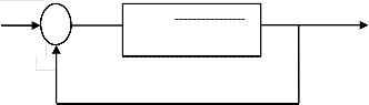
A schematic diagram of a hard disk drive head position compensator can be drawn as shown in figure 2.0
Compensator
From the diagram in figure 2.0, the read/write head model of a hard disk drive can be derived as follows
![]()

𝑑2𝜃
J
𝑑𝑡 2
![]()
𝑑𝜃
C
𝑑𝑡
+ K𝜃 = Kii ……………………….…………... 1.0
Where J = inertia of head assembly, C = viscous damping coefficient of the bearings, K = Return spring constant, Ki =
motor torque constant, 𝜃 = the angular position of the head.
Taking the Laplace transform of equation 1.0, equation 2.0 is
obtained as
J𝜃𝑠2+ C𝜃𝑠+ K𝜃 = Kii ……..………………….………… 2.0
IJSER © 2015 http://www.ijser.org
International Journal of Scientific & Engineering Research, Volume 6, Issue 4, April-2015 689
ISSN 2229-5518
𝜃 (J𝑠2 + C𝑠+ K )= Kii ………..…………………….……. 3.0
D(z) for a given sampling time Ts. Given that the Transfer
![]()
![]()
𝜃 = 𝐾𝑖
………………….………………………. 4.0
Function Gp(s) in equation 7.0
9
𝑖 𝐽𝑠 2+𝐶𝑠 +𝐾
𝜃
𝑠 2+ 0.85𝑠 + 788
![]()
………………………..……… 7.0
Since Gp (s) =
equation 5.0
![]()

G (s) = 𝐾𝑖
![]()
, the Transfer Function Gp (s) is shown in
𝑖
…..………………………………… 5.0
The Step Response for Gp(s) using MATLAB is shown in figure
4.0.
𝐽𝑠 2+𝐶𝑠+𝐾
Substituting the standard parameter values of a typical Hard Disk
Drive J = 1.0 Kgm2, C = 0.85Nm/ (rad/sec), K = 788Nm/rad, Ki
= 9.0 Nm/rad, the Transfer Function Gp (s) in equation 2.0 now leads to equation 6.0
𝐘(𝐬) 9
![]()
![]()
Gp (s) = 𝐑(𝐒) = 𝑠2 + 0.85𝑠 + 788 …………..…………... 6.0
Using MATLAB, the Transfer Function (Gp(s) ) can be derive
as follows
J = 1.0; C = 0.85; K = 788; Ki = 9.0;
num = Ki;
den = [J C K];
Gp(s) = tf (num, den)
The above MATLAB code produces the following result: Transfer function:
9
-------------------- s^2 + 0.85 s + 788
The unity feedback control system diagram of the hard disk drive head positioning system with a compensator is shown in figure 3.0
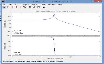
The design of the controller Gc (s) is achieved by using MATLAB to create a Bode Plot of Gp(s). Then a suitable controller Gc (s) for the stated Performance Criteria is designed and converted to Digital Compensator D(z). The Bode Plot for Gp(s) using MATLAB is shown in Figure 5.0.
R(s)
+
E(s)
Gp(s) =
9
𝑠2 + 0.85𝑠 + 788
Y(s)
Positioning System.
The Bode Plot of Gp(s) using MATLAB.
4 G C (S)-TO-D(Z) CONVERSION METHOD OF DESIGNING A DIGITAL COMPENSATOR D(Z)
This method involves the design of the controller Gc (s) for
Gp (s) in figure 3.0 and then converting the controller to
Figure 5.0 shows that a compensator is required to stabilized the performance of the Hard Disk Drive. Therefore the Bode Plot can be tuned using MATLAB control toolbox to get a suitable Lead compensator as shown in figure 6.0
IJSER © 2015 http://www.ijser.org
International Journal of Scientific & Engineering Research, Volume 6, Issue 4, April-2015 690

ISSN 2229-5518
Zero/pole/gain:
26.839 (z-1.014)
-------------------- (z-1.084)
Sampling time: 0.01
Therefore, the Digital Compensator is
![]()
G(z) = 26.839 (𝑧− 1.014)
𝑧− 1.084
……..………………. 15.0
From the MATLAB tuned diagram in figure 6.0, the Phase Gain is 9.710 at a frequency of 46.6 rad/sec. In order to achieve a phase lead of ɸ m = 450 at a crossover frequency of Wc = 3.3251 rad/sec, the Pole-Zero ratio α is given as
α−1
In MATLAB, the Transfer Function Gp(s) in equation 11.0 above can be converted to z-domain with the code below
G(z) = c2d (Gs, 0.01 , 'zoh') Transfer function:
Sine ɸm =
α+1
![]()
……………………………………………8.0
0.0004458z + 0.0004445![]()
Sine 450 = α−1
α+1
…………………………….……………9.0
-----------------------
z^2 - 1.914 z + 0.9915
Solving for α in equation 9.0, α = 5.8289
A suitable controller of the form given equation 10.0 can
be gotten as follows
𝑠 + 𝑎
Sampling time: 0.01
The code for Root locus of G(z) is![]()
Gc (s) = K
𝑠 + 𝑏
…………………………..…………..…. 10.0
rlocus(Gz)![]()
![]()
b = Wc √α … …………………..……………..… 11.0
= 3.3251 √5.8289; b = 8.0275
a = b/ α ………………………………..……….. 12.0
= 8.0275/5.8289; a = 1.3772
Since K = 26.839, Equation 10.0 now changes to
26.839 (𝑠 + 1.3772)
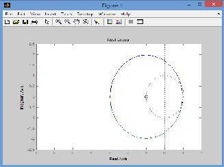
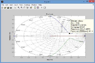
The Root locus of the control system is shown in figure 7.0
Gc (s) =
𝑠 + 8.0275
![]()
…………………..……………. 13.0
A Digital Compensator D(z) is of the form in equation 15.0 can now be derived from equation 13.0 using MATLAB
as follows
𝑧 −𝐴
![]()
G(z) =C
𝑧−𝐵
Ts=0.01;
……………………………………….. 14.0
Gc = zpk (1.3772, 8.0275, 26.839);
Dz = c2d (Rs, Ts, 'zoh')
IJSER © 2015 http://www.ijser.org
International Journal of Scientific & Engineering Research, Volume 6, Issue 4, April-2015 691
ISSN 2229-5518
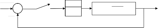
The Closed loop control system with digital compensator is shown in figure 8.0
From figure 9.0, the open-loop gain is K = 443. The closed-loop step response is
R(s)
+
-
E(s)
Ts = 0.01
E*(s)
ZOH
Gc(s)
9
Gp(s) =
𝑠2 + 0.85𝑠 + 788
Y(s)
Therefore, a lead compensator with some zeros need to be introduced with the format in equation 15.0.
𝒛−𝒂
cloop = feedback (oloop, K);
step (cloop)
𝒛−𝒃
![]()

………………………………………………. 15.0
If we choose a = -0.9863 and b = 0, D(z) is obtained using the
MATLAB code below
Dz = zpk (0.85,0,1,Ts) Zero/pole/gain:
(z-0.9863)
-------------- z
Sampling time: 0.01
The open-loop Transfer Function now becomes oloop = Gz * Dz
The Root Locus given by
rlocus(oloop);
zgrid
![]()
𝟒𝟒𝟒 (𝒛−𝟎.𝟗𝟗𝟗𝟒)
𝒛
………………………………... 16.0
The most desired features of Hard Disk Drives in this present age of computers are very high speed data storage/retrieval and Reliability (data integrity preservation). In order to meet the information/data storage requirements of this modern age, a significantly high level performance is the main goal of every Hard Disk Drive. It can be inferred from equations 13.0 and 15.0 that a design of an effective compensator to eliminate the inadequacies of the Hard Disk Drive Read/Write Head positioning system for improved performance has been achieved.
IJSER © 2015 http://www.ijser.org
International Journal of Scientific & Engineering Research, Volume 6, Issue 4, April-2015 692
ISSN 2229-5518
[1] JianbinNie (2011). Control Design and implementation of
Hard Disk Drive servo. University of Califonia, Berkeley.
[2] K. Aruga, M Suwa, K Shimizu (2007). A study on positioning error caused by flow induced vibration using helium-filled hard disk drives.Magnetics, IEEE publication, Volume 43.
[3] Kenn Oldham, Sarah Felix, Richard Conway, and Roberto Horowitz (2009). Design and Control of a Dual- Stage Disk Drive Servo System with a High-Aspect Ratio Electrostatic Microactuator American Control Conference, Washington, USA.
[4] K. Z. Gao, O Heinonen, Y Chen (2009). Read and write processes, and head technology for perpendicular recording. Journal of Magnetism and Magnetic Elsevier publication, Volume 27.
[5] Masahito Kobayashi and Roberto Horowitz (2010).
Track Seek Control for Hard Disk Dual-Stage Servo
Systems. Journal of IEEE, Volume 37.
[6] Marios Hadjieleftheriou, Apostolos N. Papadopoulos and Donghui Zhang. (2007). Disk Storage and Basic File Structure. Northeastern University.
[7] Mathsworks (2014). MATLAB Codes. MathWorks, Inc Natick, Massachusetts, www.mathworks.com/examples, USA.
Technology, Poland.
[12] Takenori Atsumi (2009). Head-Positioning Control of Hard Disk Drives through the Integrated Design of Mechanical and Control Systems. Faculty Mechanical Engineering Research Laboratory, Kirihara, Fujisawa, Kanagawa 252-8588, Japan.
[8] M. J. Nigam (2007). Introduction to Hard Disk
Drives.Indian Institute of Technology, Bombay.
[9] Roman Wituła and Tomasz Trawiński (2012).
Modelling of HDD head positioning systems regarded as robot manipulators using block matrices. Faculty of Electrical Engineering, Silesian University of Technology, Poland.
[10] Thummeti Buchi Reddy and M. J. Nigam (2007). Design and Implementation of a Hard Disk Drive Read/Write Head Controller Using FPGA for Optimal Performance. Indian Institute of Technology Roorkee, Roorkee, INDIA-247667.
[11] Tomasz Trawiński (2012). Kinematic chains of branched head positioning system of hard disk drives. Faculty of
Electrical Engineering, Silesian University of
IJSER © 2015 http://www.ijser.org