Since the LED chip bond pad surface condition can directly affect wire bond interfacial adhesion quality, various surface characterization methods were conducted. The surface mor- phology of bond pad surface was observed by FESEM (FEI,
International Journal of Scientific & Engineering Research, Volume 5, Issue 12, December-2014 908
ISSN 2229-5518
Comparison of Argon and Oxygen Plasma Treatments on LED Chip Bond Pad for Wire Bond Application
Hui Yuen Peng, Mutharasu Devarajan, Teik Toon Lee
Abstract— The efficiencies of Argon and Oxygen microwave plasma treatments were compared in terms of contaminant removal and wire bond interfacial adhesion in this paper. The efficiency in contaminant removal was analysed by applying Argon and Oxygen plasma treatments to Light Emitting Diode (LED) chip bond pad prior to wire bonding process. The bond pad samples were then wire-bonded and examined with ball shear test to investigate the improvement of wire bond interfacial adhesion. The results show that Oxygen plasma treatment can remove the bond pad surface contaminant and improve the wire bond interfacial adhesion more effectively compared to Argon plasma treatment.
Index Terms— Plasma treatment, Surface contaminant, W ire bond, Light Emitting Diode, Argon and Oxygen, Chip bond pad and Surface free energy
—————————— ——————————
HERMOSONIC wire bonding is one of the critical packag- ing processes for Light Emitting Diode (LED) device where fine wires are mechanically bonded onto the LED
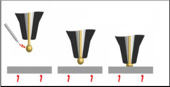
chip bond pad for electrical connections [1]. During thermo- sonic wire bonding, gold wire is guided through a hole in the capillary of wire bonder, and an electrical flame-off is used to melt the tail of the gold wire into a spherical ball (free air ball) by high-voltage electrical discharging. The free air ball is then ultrasonic rubbed and compressed onto the heated LED chip bond pad to form a ball bond. An overview of the thermosonic wire bonding process is shown in Fig. 1.
In general, LED devices in automotive applications usually stressed under extreme conditions with a high temperature above 150°C during operation [2]. Mechanical stress that in- duced to the wire bond due to thermal expansion coefficient mismatch under high operating temperature causes the deg- radation of wire bond interfacial adhesion and the failure of electric contacts in LED devices via detachment [3]. In auto- motive applications, the “lifted ball bond” issue remains a potential critical point for LED device reliability [4]. Surface contamination at the bonding interface is one of the key factor that cause “lifted ball bond” issue to arise [5] [6]. Thus, LED chip bond pad surface cleaning prior to the wire bonding pro- cess is requested in order to improve the wire bond reliability.
Plasma treatment is the dominant cleaning method used in industry currently due to its advantages of fast processing and being damage-free to microelectronic devices [7]. Thus, the efficiencies of Argon and Oxygen microwave plasma treat- ments were compared in terms of contaminant removal and
tron Microscopy (FESEM), X-ray photoelectron spectroscopy (XPS), Atomic Force Microscopy (AFM) and contact angle measurement respectively. In order to investigate the efficien- cy of Argon and Oxygen plasma treatments on wire bond in- terfacial adhesion improvement, the bond pad samples were wire-bonded and examined with ball shear test.
In order to investigate the efficiency of Argon and Oxygen plasma treatments, gold LED chip bond pad samples were treated inside a microwave generator plasma system (Tepla GIGA 80 Plus). During plasma treatment, argon and oxygen gas was introduced into the plasma chamber with a flow rate of 40ml/min. Once the process pressure was stabilized, a pulse DC power source with high voltage was supplied via electrodes at both sides of the plasma chamber. The pulse DC power supplied in Argon and Oxygen plasma treatments were set to 350W and 500W accordingly. In this experiment, the LED chip bond pad samples were plasma treated with the time interval of 45, 90, 135 and 180 seconds respectively.
Since the LED chip bond pad surface condition can directly affect wire bond interfacial adhesion quality, various surface characterization methods were conducted. The surface mor- phology of bond pad surface was observed by FESEM (FEI,
Step 1
Step 2
wire bond interfacial adhesion in this paper. Argon and Oxy- gen plasma treatments were applied to LED chip bond pad prior to wire bonding process respectively with the time inter- val of 45, 90, 135 and 180 seconds. These bond pad samples were then characterized with Field-Emission Scanning Elec-
Electrical flame-off
Capillary
Free Air
Ball
Step 3
Force & Ultrasonic vibration
————————————————
• Hui Yuen Peng is currently pursuing masters degree program in School of
PHysics in University Sains Malaysia.
IJSER © 2014
Heat Heat Heat
Fig. 1. Thermosonic wire bonding
International Journal of Scientific & Engineering Research, Volume 5, Issue 12, December-2014 909
ISSN 2229-5518
Nova NanoSEM 450) at X5000 magnification. The chemical composition of bond pad surface was examined by XPS (Esca- lab 250). The surface roughness of bond pad surface was ana- lyzed by measuring the Root Mean Square (RMS) roughness with AFM (NanoScope Analysis 1.20) with a scan area of 5µm x 5µm. Besides that, contact angle measurement was also per- formed with a contact anglometer (Cam Micro, Tantec) by using sessile drop method. Bond pad surface free energy was then calculated from the contact angle obtained with Young- Dupre equation. In order to explain the surface free energy results, high resolution XPS measurement was employed to characterize the Carbon (C1s) chemical bonding state of bond pad surface.
Further to investigate the influence of Argon and Oxygen plasma treatments to wire bond interfacial adhesion quality, a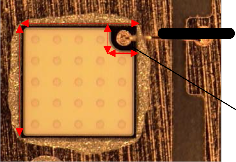
38µm of 99.99% gold wire was bonded onto the bond pad samples with an automated wire bonder (ASM Eagle-XL) as shown in Fig. 2. The dimensions of LED chip and the chip bond pad used were 1000µm x 1000µm and 158µm x 158µm respectively. During wire bonding, the wire bonding parame- ter such as bond force, bond time, bond temperature and ul- trasonic power were optimized before the study and were set to 60gmf, 25ms, 150ºC and 100W accordingly. The ball shear test was then carried out with a ball shear tester (XYZTEX Condor 10) to examine the wire bond interfacial adhesion quality. Each testing category in this experiment consists of 30 samples.
Wire bond
Before plasma treatment, there are some white dots observed on the bond pad surface. The white dots become lesser after Argon plasma treatment, whereas the white dots completely disappear after Oxygen plasma treatment. The scratch mark on bond pad surface is the result from physical contact be- tween probe tip and bond pad during electrical testing after LED chip fabrication [8].
Table I summarizes the atomic concentrations of elements detected on the Gold(Au) bond pad surfaces through XPS. Before plasma treatment, Carbon(C), Oxygen(O) and Nick- el(Ni) impurities are detected with an atomic concentration of
10.72%, 8.97% and 4.44% respectively. The white spots as ob- served in Fig. 3 are the organic contaminant introduced by LED chip manufacturing material, i.e., passivation residue and photoresist residue, and LED package assembly processes be- fore wire bonding, i.e., oxidation and epoxy outgassing during die attach epoxy curing, as high C impurity is detected [9] [10]. The appearance of O and Ni impurities due to the Ni migrates through the thin Au bond pad layer during high temperature processing, leading to oxidation upon exposure to environ- ment after it reaches the bond pad surface [11]. After 90 se- conds of Argon plasma treatment, the atomic concentration of C, O and Ni impurities reduces to 3.96%, 5.42% and 1.83%. Meanwhile, after 90 seconds of Oxygen plasma treatment, the atomic concentration of C, O and Ni impurities reduce to
1.25%, 7.38% and 1.01%. The C and Ni impurities on the bond pad surface after Argon plasma treatment is lesser compared to Oxygen plasma treatment. Although bond pad surface after Oxygen plasma treatment has higher O impurity content compared to Argon plasma treatment, these O impurities can
1000µm
1000µm
158µm
158µm
Chip bond pad
improve surface free energy and wire bond interfacial adhe-
sion by adding –OH and -OOH groups, which will be dis-
cussed in the next section. FESEM and EDX results conclude
that Oxygen plasma treatment can remove the contaminant
more effectively than Argon plasma treatment.
TABLE I
ATOMIC CONCENTRATION OF ELEMENTS DETECTED ON
Fig. 2. Wire bond in LED package
GOLD(AU) BOND PAD SURFACES THROUGH EDX![]()
Atomic concentration of element (%)
Figure 3 displays the FESEM image of bond pad (a) before
Plasma
![]()
treatment
None
![]()
Testing
point
Bond pad
White dots
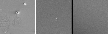
plasma treatment, (b) after 90 seconds of Argon plasma treat- ment and (c) after 90 seconds of Oxygen plasma treatment.
Argon Bond pad
Oxygen Bond pad
![]()
(a)
(b)
(c)
100µm
100µm 100µm
Fig. 3. FESEM image of bond pad surface (a) before plasma treatment (b) after Argon plasma treatment and (c) after Oxygen plasma treatment
IJSER © 2014 http://www.ijser.org
International Journal of Scientific & Engineering Research, Volume 5, Issue 12, December-2014 910
ISSN 2229-5518
During plasma treatment, high voltage is applied via elec- trodes at both sides of plasma chamber. Electrons from cath- ode accelerate towards anode and collide with the Argon and Oxygen gas atoms in the chamber. In Argon plasma treatment, Argon gas atoms are ionized into Ar+ ions after colliding elec- trons [12]. These heavy and inert Ar+ ions remove the surface contaminant through mechanical bombardment [13]. Mean- while, in Oxygen plasma cleaning, Oxygen gas atoms are ion- ized into O monoatomic oxygen, O+ and O2+ ions after collid- ing with electrons. These high reactive O monoatomic oxygen, O+ and O2+ ions chemically react with organic contaminant to form volatile molecules, such as H2O, CO and CO2 [14]. The volatile molecules were then evacuated from plasma chamber before re-deposition occurs. Moreover, O+ and O2+ ions can also remove the surface contaminant through mechanical bombardment during the treatment. Thus, Oxygen plasma treatment which removes the surface contaminant through both chemical reaction and mechanical bombardment is more efficient than Argon plasma treatment which just removes the surface contaminant through mechanical bombardment.
Fig. 4 displays the AFM morphology image of bond pad sur- face (a) before plasma treatment, (b) after 90 seconds of Argon plasma treatment and (c) after 90 seconds of Oxygen plasma treatment. Before plasma treatment, the peaks on the bond pad surface are blunt and wide. The tall flat irregularity peaks observed on the bond pad are the white spots in FESEM image as shown in Fig. 3(a). After Argon and Oxygen plasma treat-
ments, the peaks on the bond pad surface become sharper and thinner. Fig. 5 illustrates the average RMS roughness of bond pad surface relative to Argon and Oxygen plasma treatment duration. Before plasma treatment, the average RMS rough- ness of bond pad surface is 1.188nm. The average RMS rough- ness of bond pad surface increases 22.22% into 1.452nm after
180 seconds of Argon plasma treatment, whereas increases
10.61% into 1.314nm after 180 seconds of Oxygen plasma
treatment. This shows that Argon plasma treated surfaces
were rougher than Oxygen plasma treated surface
During plasma treatment, Ar+, O+ and O2+ ions with high
kinetic energy are mechanically bombarded onto the bond pad
surface to knock-off the contaminant. This ion bombardment
also simultaneously gives rise to the surface etching, leading
to the change of bond pad surface structure and the increase of
bond pad surface roughness [15]. Argon which has higher
atomic mass of, i.e., 39.948u than oxygen, i.e., 15.999u, causing
the surface etching effect of bond pad is more severe [16]. Thus, the bond pad surface after Argon plasma treatment is rougher compared to Oxygen plasma treatment.
Dispersive adhesion is a mechanism for adhesion which at- tributed to the molecular interactions between two contacting bodies, where each has a region of positive and negative po- larity [17]. These dispersion adhesion intermolecular interac- tions include polar interactions (dipole-dipole, dipole-induced dipole and hydrogen bond interactions) and non-polar or dis- persive interactions (instantaneous dipole interaction). Thus, surface free energy also consists of two components which are
polar component, ![]() and non-polar or dispersive component,
and non-polar or dispersive component, ![]() respectively [18]. According to Young-Dupre equation, the overall bond pad surface free energy,
respectively [18]. According to Young-Dupre equation, the overall bond pad surface free energy, ![]() can be calculated by determining the surface free energy components through
can be calculated by determining the surface free energy components through
contact angle measurement of two different liquids, i.e., DI water and Diiodomethane on bond pad surface as given in (1) and (2)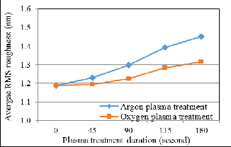
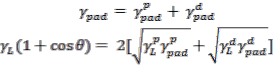
(1)
(2)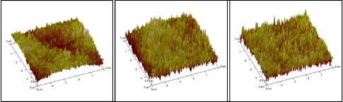
Fig. 5. Average RMS roughness of bond pad surface relative to plasma treatment duration![]()
![]()
where θ is the contact angle of the liquid, is the overall sur- face free energy of liquid, and are the polar and
(a)
(b)
(c)
Fig. 4. AFM image of bond pad surface (a) before plasma treatment (b) after Argon plasma treatment and (c) after Oxygen plasma treatment
IJSER © 2014 http://www.ijser.org
International Journal of Scientific & Engineering Research, Volume 5, Issue 12, December-2014 911
ISSN 2229-5518
dispersive surface free energies of bond pad, ![]() and
and ![]() are the polar and dispersive surface free energies of liquid.
are the polar and dispersive surface free energies of liquid.
Fig. 6 displays the average bond pad surface free energy relative to plasma treatment duration. The bond pad before plasma treatment has a surface free energy of 23.6mJ/m2. The surface free energy increases drastically in the initial stage and slowly increases as plasma treatment duration increase. The bond pad surface free energy increases 201.4% into 71.2mJ/m2 after 180 seconds of Argon plasma treatment, whereas in- creases 232.24% into 78.5mJ/m2 after 180 seconds of Oxygen plasma treatment. This shows that Oxygen plasma treatment can improve bond pad surface free energy more effectively than Argon plasma treatment.
Generally, surface free energy is significantly affected by the polar component on the bond pad surface [19]. Oxygen plasma treatment which able to remove the carbon impurities and reduce the weak polarity of C-C/H bonds on the bond pad surface more effectively, causing the surface free energy improved better compared to Argon plasma treatment [20]. Moreover, bond pad surface free energy has better improve- ment after Oxygen plasma treatment due to more high polari- ty and strong hydrogen bonds are introduced, such as C=O, C-OH, C-OOH bonds [13]. Fig. 7 displays Carbon (C1s) XPS band of bond pad surface (a) before plasma treatment, (b) after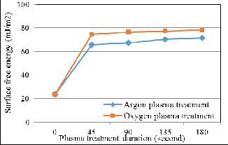
90 seconds of Argon plasma treatment and (c) after 90 seconds of Oxygen plasma treatment. Before plasma treatment, C-C/H (284.6eV) and C-O/OH (285.6eV) bonds were detected on bond pad surface. After Argon plasma treatment, C=C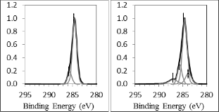
Fig. 6. Average bond pad surface free energy relative to plasma treatment duration
the bond pad surface. Meanwhile, after Oxygen plasma treat- ment, C=C, C=O and C-OOH (289eV) bonds have been intro- duced on the bond pad surface. During plasma treatment, Ar- gon and Oxygen gas atoms are excited into higher energy state after collision with electrons and fall back to ground state with the emission of photons. These emitted photons break C–C/H and C–O bonds and lead to the formation of C=C bonds on bond pad [14]. At the same time, significant carbon radicals are also formed onto the bond pad surface during the plasma treatment [14]. C=O and C-OH bonds are formed after Argon plasma treatment as the carbon radicals react with oxygen contaminant inside the plasma chamber during the treatment. Meanwhile, C=O, C-OH, C-OOH bonds are formed after Oxy- gen plasma treatment as the carbon radicals react with oxygen plasma during the treatment. C-OOH bond is not introduced on the bond pad surface treated by argon plasma due to the less of oxygen component inside the plasma chamber during the treatment [13].
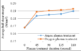
Ball shear test is the dominant test method used in industry to assess the wire bond interfacial adhesion quality, whereas ball shear strength is the strength that a ball bond can withstand from being sheared off. Figure 8 illustrates the average ball shear strength relative to Argon and Oxygen plasma treatment duration. Before plasma treatment, the average ball shear strength of bond pad surface is 0.167N/mm2. The average ball shear strength increases 12.98% into 0.189N/mm2 after 180 seconds of Argon plasma treatment, whereas increases 14.77% into 0.193N/mm2 after 180 seconds of Oxygen plasma treat- ment. This shows that Oxygen plasma treatment can improve wire bond interfacial adhesion more effectively than Argon plasma treatment.
Generally, interfacial adhesion of wire bond is significantly
influenced by the contact area between wire bond interfaces.
This is because larger contact area contribute to a higher de-
gree of the mechanical interlocking between wire bond inter-
faces. Liu et al. proposed that an increase of surface free ener-
gy is comparable to an increase of the contact area between
two contacting bodies [13]. Thus, Oxygen plasma treatment
which able to improve bond pad surface cleanliness and sur-
face free energy more effectively causes the wire bond interfa-
cial adhesion has better improvement compared to Argon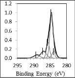
plasma treatment. Although bond pad surface after Argon
(a)
C-C/H
(b)
C-C/H
(c)
C-C/H
C-O/OH
C-O/OH C-O/OH
C=C C=C
C=O
C=O C-OOH
Fig. 7. Carbon (C1s) XPS band of bond pad surface (a) before plasma treatment (b) after Argon plasma treatment and (c) after
Oxygen plasma treatment
(283.8eV) and C=O (287eV) bonds have been introduced on
plasma treatment is rougher and has larger contact area com-
IJSER © 2014 http://www.ijser.org
International Journal of Scientific & Engineering Research, Volume 5, Issue 12, December-2014 912
ISSN 2229-5518
Fig. 8. Average ball shear force relative to plasma treatment duration
pared to Oxygen plasma treatment, its impact to wire bond interfaces adhesion quality changes is negligible compared to bond pad surface cleanliness and surface free energy as the RMS roughness difference is just in nanometer (nm) scale.
The efficiency of Argon and Oxygen plasma treatments was compared in terms of contaminant removal and wire bond interfacial adhesion quality in this paper. The bond pad sur- face characterization results show that Oxygen plasma treat- ment which removes the surface contaminant through both chemical reaction and mechanical bombardment is more effi- cient than Argon plasma treatment which just removes the surface contaminant through mechanically bombardment. Thus, bond pad surface after Oxygen plasma treatment with lower carbon impurity content has better surface free energy than Argon plasma treatment as evaluated through contact angle measurement. The ball shear test results show that Oxy- gen plasma treatment can improve the wire bond interfacial adhesion more effectively compared with Argon plasma treatment as higher ball shear force is obtained.
This work is supported by OSRAM OptoSemiconductor Sdn. Bhd.
[1] W.Y. Yong, X.W. Zhang, T.C. Chai, A. Trigg, N. Bt. Jaafar, and G.Q.
Lo, “In Situ measurement and stress evaluation for wire bonding us- ing embedded piezoresistive stress sensors,” IEEE Trans. Compon. Packag. Manuf. Technol., vol. 3, no. 2, pp. 328-335, 2013
[2] T. Uno, and K. Tatsumi, “Thermal reliability of gold–aluminum bonds encapsulated in bi-phenyl epoxy resin,” Microelectron. Reliab., vol. 40, no. 1, pp.145-153, 2000.
[3] L.Yang, A. Agyakwa, and C.M. Johnson, “Physics-of-failure lifetime prediction models for wire bonds interconnect in power electronics modules,” IEEE Trans. Device Mater. Reliab., vol. 13, no.1, pp. 9-16,
2013.
[4] D.M. Knotter, I.A. Rink, W.A.P. Claasen, and J.H.M. Philipsen, “Bond pad surface quality for reliable wire bonding,” Microelectron. Eng., vol. 88, no. 1, pp. 3452-3458, 2011.
[5] L.F. Lew, A.N.L. Lau, “Influence of copper contamination on contact
quality between gold wire and Nickel-Palladium bond pad through X-ray photoelectron spectroscopy,” in Proc. 17th IEEE Int. Symp. Phys. Failure Anal. Integr. Circuits, Singapore, 2010, pp. 1-4.
[6] F. Zong, Z.J Wang, Y.B. Xu, J.Y. Niu, and H.M. Zhang, “Tin contami- nantion in PQFN package and its effects on wire bondability,” Micorelectron. Int., vol. 30, no. 3, pp. 176-186, 2013.
[7] G.G. Harman, Wire bonding in microelectronics: Materials, process-
es, reliability and yield (2nd ed.), New York: McGraw-Hill, 1997, pp.
133-156.
[8] G. Hotchkiss, G. Ryan, W. Subido, J.Broz, S. Mitchell, R. Rincon, R.
Rolda, and L. Guimbaolibot, “Effects of probe damage on wire bond integrity,” in Proc. 51st IEEE Electron. Compon. Technol. Conf., Orlan- do, FL, 2001, pp. 1175-1180.
[9] F.Y. Lim, and C.L.W. Yew, “Die attach materials impacts to copper wire bonding: New challenges,” in Proc. 14th IEEE Electron. Packag. Technol. Conf., Singapore, 2012, pp. 263-268.
[10] M.M.Khan, T.S. Tarter, H.Fatemi, “Aluminum bond pad contamina- tion by thermal outgassing of organic material from silver-filled epoxy adhesives,” IEEE Trans. Compon., Hybrids, Manuf. Technol., vol.
10, no. 4, pp. 586-592, 1987.
[11] Y.H. Chan, J.K. Kim, D.M. Liu, Peter Chou, Y.M. Cheung, and M.W.
Ng, “Effect of plasma treatment of Au-Ni-Cu bond pads on process windows of Au wire bonding,” IEEE Trans. Adv. Packag., vol 28, no.
4, pp. 674-684, 2005.
[12] G. Takyi, and N.N. Ekere, “Study of the effects of PCB surface finish on plasma process time for lead-free wave soldering,” Soldering Surf. Mount Technol., vol. 22, no. 2, pp. 37-42, 2010.
[13] D. Liu, P. Chen, M. X. Chen, and C. Lu, “ Effects of argon plasma treatment on the interfacial adhesion of PBO fiber/bismaleimide composite and aging behaviors,” Appl. Surf. Sci., vol. 257, no. 1, pp.
10239-10245, 2011.
[14] N. Gomathi, and S. Neogi, “Surface modification of polypropylene using argon plasma: Statical optimization of the process variables,” Appl. Surf. Sci., vol. 255, no. 1, pp. 7590-7600, 2009.
[15] J.H. Lee, K.S. Hwang, T.S. Kim, J.W. Seong, K.H. Yoon, and S. Ahn, “Effect of oxygen plasma treatment on adhesion improvement of Au Deposited on Pa-c Substrates,” J. Korean Physical Society, vol. 44, no. 5, pp.1177-1181, 2004.
[16] D. Berman, and J. Krim, “Impact of oxygen and argon plasma expo- sure on the roughness of gold film surfaces,” Thin Solid Film, vol. 520, no. 1, pp. 6201-6206, 2012.
[17] W.C. Wake, “Theories of adhesion and uses of adhesives: a review,”
Polymer, vol. 19, no. 3, pp. 291-308, 1978.
[18] Y.S. Lin, W.J. Lin, and L.Y. Chiu, “Enhanced solder wettability of oxidized-copper with lead-free solder via Ar-H2 plasmas for flip- chip bumping: the effects of H2 flow rates,” Soldering Surf. Mount Technol., vol. 24, no. 3, pp. 183-190, 2012.
[19] X.M. Yang, Z.W. Zhong, E.M. Diallo, Z.H. Wang, and W.S. Yue, “Sili-
con wafer wettability and aging behaviors: Impact on gold thim-film morphology,” Mater. Sci. Semicond. Process., vol. 26, no. 1, pp. 25-32,
2014.
[20] K. Hermansson, U. Lindberg, B. Hok, and G. Palmskog, “Wetting properties of silicon surfaces,” in Proc. Transducers 91, IEEE Int. Conf. Solid-State Sens. Actuators, San Francisco, CA, USA, 1991, pp.193-196.
IJSER © 2014 http://www.ijser.org