International Journal of Scientific & Engineering Research, Volume 4, Issue 11, November-2013 1174
ISSN 2229-5518
CONTROL OF ROBOTIC ARM USING MACHINE VISION
M.Shri Harish1, R.Hushein2, S.Jayavelu3
Asst professor, School of Mechanical Engineering, Veltech Dr.RR & Dr.SR Technical University,Avadi, Chennai. Asst professor, School of Mechanical Engineering, Veltech Dr.RR & Dr.SR Technical University,Avadi, Chennai. Asst professor, School of Mechanical Engineering, Veltech Dr.RR & Dr.SR Technical University,Avadi, Chennai. mshriharishee@yahoo.com,husheinece@gmail.com,s.jayavelu.me@gmail.com
Every invention has a aim to reduce humans effort and make it easy for his life.In this regard this paper is focused on easy control of robotic arm using simple hand movements. The movement control can be used for heavier machinery like JCB earth movers which can also be used in delicate environment like saving lives in earth quake demolished sites. Image processing techniques is involved in realizing the hand movement, MATLAB is utilized to complete image processing part , To implement the approach on a real-time application, a Personal Computer interface was designed to control the movements of a four degree of freedom robot arm by transmitting the orders via radio frequency circuits.
I. INTRODUCTION
Since many years people try to replace human work with machines. Machines called robots are faster and more effective than people. The term robotics is practically defined as the study, design and use of robot systems for manufacturing [1]. Robots are generally used to perform unsafe, hazardous, highly repetitive, and unpleasant tasks. They have many different functions such as material handling, assembly, arc welding, resistance welding and machine tool load and unload functions, painting, spraying, etc. Many elements of robots are built with inspiration from the nature. Construction of the manipulator as the arm of the robot is based on human arm. The robot has the ability to manipulate objects such as pick and place operations. It is also able to function by itself. the development of electronic industry. robot system technology has been expanded increasingly. As one such application, the service robot with machine vision capability has been developed recently. Machine vision (MV) is the technology and methods used to provide imaging-based automatic inspection and analysis for such applications as automatic inspection, process control, and robot guidance in industry. Individuals with motor impairments such as those with paraplegia, spinal cord injuries, war-time injuries or amputations rely on others to assist them there in daily activities. Advances in assistive technologies have begun to provide an increase in independence for these individuals, but there is great
potential for further technological developments to significantly improve their abilities, independence, and overall quality of life. One of the greatest challenges faced in assistive technology, however, is that control options are extremely limited when the target users have little or no use of their limbs. For example, a mouse is useless to someone without arms. Our approach of this problem is tele-presence , using a robotic arm that act like human’s arm. User controls the arm by just moving his hand in front of webcam and by using a MATLAB software, this movement can be detected , and the laptop sends control signals to the arm. Using a mobile or stationary robot , this technique can be used to keep the user in safe place and send a machine that can be easily replaced or rebuilt.
The robotic arm will be controlled by a serial servo controller circuit board that is base on a Programmable Interface Controller (PIC) 16F84, a type of flash programmable microcontroller shows in Figure 2. The main objective of designing using a microcontroller is that a large amount of electronics needed for certain applications can be eliminated. The PIC is considered as the brain of the whole device that operates in a close loop control process. This controller board is used to interface the arm to a personal computer (PC). In Visual Servoing the motion of a robot is controlled based on video image information. A challenge is that cameras encode information in a 2D pixel coordinate system, while most robots have rotational joints and motors. The conventional, position-based approach is to calibrate both the camera and robot in a common Cartesian base coordinate frame. However such calibration is cumbersome and error prone. Our approach is to instead do away with the base frame, and directly estimate the coordinate transform from the cameras (usually one or two) to the robot motor space. The key insight is that when the camera observes the motion of the robot one gains partial information about this coordinate transform. This partial information can be gathered over time into either
IJSER © 2013 http://www.ijser.org
International Journal of Scientific & Engineering Research, Volume 4, Issue 11, November-2013 1175
ISSN 2229-5518
a local linear model, a Visual-Motor Jacobian, or a global non-linear model, a Visual-Motor Function. The control is limited to nine positions to select the arm part (upper limb, limb, hand and forceps or grip) and to command the selected part (up, down, left right and stop). These commands are necessary to control the movement of the robotic arm, Up movement, Down movement, stop, turn left and turn right. The number of details in image was kept to a minimum both to make the application simpler and easier for the user. The block diagrams are shown in below.

The mechanical design of the robot arm is based on a robot manipulator with similar functions to a human arm [6-8]. The links of such a manipulator are connected by joints allowing rotational motion and the links of the manipulator is considered to form a kinematic chain. The business end of the kinematic chain of the manipulator is called the end effector or end-of-arm-tooling and it is analogous to the human hand. Figure 3 shows the Free Body Diagram for mechanical
design of the robotic arm. As shown, the end effector is not
included in the design because a commercially available gripper is used. This is because that the end effector is one of the most complex parts of the system and, in turn, it is much easier and economical to use a commercial one than build it.
The mechanical design was limited to 4 DOF mainly because that such a design al- lows most of the necessary movements and keeps the costs and the complexity of the robot competitively. Accordingly, rotational motion of the joints is restricted where rotation is done around two axis in the shoulder and around only one in the elbow and the wrist, see Figure 3.
The robot arm joints are typically actuated by electrical motors. The servo motors were chosen, since they include encoders which automatically provide feedback to the motors and adjust the position accordingly. However, the disadvantage of these motors is that rotation range is less than
180° span, which greatly decreases the region reached by the arm and the possible positions [9]. The qualifications of servo motors were selected based on the maximum torque required by the structure and possible loads. In the current study, the material used for the structure was acrylic Figure 4 shows the force diagram used for load calculations. The calculations were carried out only for the joints that have the largest loads, since the other joints would have the same motor, i.e. the motor can move the links without problems. The calculations considered the weight of the motors, about 50 grams, except for the weight of motor at joint B, since it is carried out by link BA.
Wd = 0.011 kg (weight of link DE) Wcd = 0.030 kg (weight of link CD) Wbc = 0.030 kg (weight of link CB)
L = 0.5kg (load)
IJSER © 2013 http://www.ijser.org
International Journal of Scientific & Engineering Research, Volume 4, Issue 11, November-2013 1176
ISSN 2229-5518
Cm = Dm = 0.050 kg (weight of motor) Lab = 0.18m (length of link AB)
Lbc = 0.14 m (length of link BC) Lcd = 0.14 m (length of link CD) Lde = 0.05 m (length of link DE)
∑Fy= (L+Wgrip+Dm+Wc+Cm)g-Cc=0 (1) Cc=6.28N (2)
Force acting at b
∑Fy=(L+Wgrip+Dm+Wc+Cm+Wb)g-Cb=0 (3) Cb=6.57N (4)
Force acting at a
∑Fy=(L+Wgrip+Dm+Wc+Cm+Wb+bm+Wa)g
-Ca=0 (5) Ca=7.35N (6)
Moment at point at c
∑Mc=-(WcLcd/2)-Wd(Lcd+(Lde/2))-L(Lcd+Lde)- Dm(Lcd)+Mc=0 (7)
Mc=109.92Nm (8) Moment at point at b
∑Mb=-L(Lbc+Lcd+Lde)-Wd(Lbc+Lcd+Lde/2)Dm(Lbc+Lcd)-
Wc(Lbc+Lcd/2)- Cm(Lbc)Wb(Lbc/2)+Mb=0 (9)
Mb=318.34Nm (10)
Moment at point at a
∑Mb=-L(Lab+Lbc+Lcd+Lde)-Wd(Lab+Lbc+Lcd+Lde/2)- Dm(Lab+Lbc+Lcd)-Wc(Lab+Lbc+Lcd/2)-Cm(Lab+Lbc)- Wb(Lab+Lbc/2) –Bm(Lab)-Wa(Lab/2)+Ma=0 (11)
Ma=329.34Nm (12)
Once the initial dimensions for the robot arm and the motor were defined, the design were carried out using the Solid Works platform; design should carefully take into account the thickness of the acrylic sheet and the way that the pieces would be attached to each other. The acrylic sheet used to make the robot is 1/8 thickness and that thin sheet was chosen because it easier for machining and less weight with a good resistance.
During design, we faced some difficulties due to the way of joining thin acrylic parts strongly. It was needed tools to burn and join the acrylic parts and that weren’t available and the team considered that a mechanical junction based on screws and nuts would be much strong than other alternatives, such as glue for example. In order to accomplish this, a small feature was designed which allowed to fasten the bolts with the nuts without having to screw in the thin acrylic layer. By end of design, each part was printed in full scale in cardboard paper and then we verified all the dimensions and the interfaces of the assembly. In turn, we built the first prototype of the robot arm. Next, parts of the robot arm were machined from the acrylic sheet using a circular saw and Dermal tools. The detailing on the parts was done in a professional workshop since the parts of robot arm were too small and it is not an easy for accomplishing such small and accurate cuts. During assembling the robot parts with the motors, few problems pop up. There were critical points that did not resist the fastening and, in turn, may break down; hence, reinforcements in these points were considered.
As for the gripper, the parts are tightened with enough force to allow the pieces to move freely without friction and unwanted sound but enough to hold the parts in place. The final step is to mount the gripper to the wrist. A serial servo controller board is constructed using PIC16F84A as the
‘brain’ of the controller [4]. This serial servo controller board will be used in controlling the robot arm by means of controlling eight servos via a serial connection to a personal computer (PC).
To validate the right positioning of the robotic arm, inverse kinematics calculations are carried out. Such calculations are
IJSER © 2013 http://www.ijser.org
International Journal of Scientific & Engineering Research, Volume 4, Issue 11, November-2013 1177
ISSN 2229-5518
used to obtain the angle of each motor from a position given by using the Cartesian coordinate sys- tem, as shown in Figure 6. Each motor will have a spe- cific function: the motor located in the A union positions the final element in the y axis, the motors B and C posi- tions the final element in the x and z axis.
The problem was simplified by using the xz plane, as shown in Figure 7. In which the following known values were defined [9]:
LAB: the forearm length.
LBC: the arm length.
z: the position in the z axis. x: the position in the x axis. y: the position in the y axis.
Using trigonometry relations, as shown in Figure 7, the motor angles θ2 and θ1 are obtained, as seen in Equations (13) and (14).
ᶿ2 =180̊-arcCos((LAB2+LBC2-x2-z2)/(2*LAB*LBC))
(13)
ᶿ1=arcTan(z/x)+arcCos((LAB2-LBC2+x2+z2)/(2*LAB* (x2+ z2)^1/2))
(14)
Figure 6. Coordinate system.
Figure 7. xz Plane.
ᶿ0 = arcTan(y/x) (15)
The motor B is going to use θ1 and the motor C is go- ing to use θ2. The angle for the motor A is calculated as seen in Equation (15). With these calculations, the angles of servomotors are obtained and in turn they take the ac- tion to move the whole structure to the specific position.
Assistive technology provides independence for people. While assistive devices such as powered wheelchairs and menu-driven robot arms improve the quality of life for some, others are unable to effectively use these technologies due to their limited user-interaction methods. This paper shows a glimpse of an innovative application of image processing in advanced robots, which are capable of making their own decisions in order to be truly autonomous in dynamic environments. In this work, a new algorithm is developed to control jointed arm robot for pick and place operations using image processing. A simple web camera is used to control the shoulder arm within the work volume by taking the images of two reference points on the shoulder arm and object as third reference point. Computer process the images and determine the centre distances between the shoulder arm reference points and the object. Based on difference in the centre distances, the computer will actuate the shoulder arm towards the object until the difference becomes zero. The upper and fore arms are actuated using reverse kinematics. The algorithm is evaluated in simple computer controlled jointed arm robot for pick and place operations.
The controller circuit functions as a standalone circuit and it works independently from the robots main CPU. Hence, it does not take any processing power from the main CPU. This controller circuit provides many advantages compared with other circuits as the response time is less than 300 ms, it requires only a 5 V DC power supply and it can support CPU mode and manual mode whereby the manual mode is connected to a keypad and CPU mode is connected to a microcontroller.
Here the circuit was constructed into on breadboard for
testing and training. Testing and training the circiut in manual mode requires the keypad and microphone. When the circuit is powered on, the PIC micro controller checks the static RAM and display “00” on the 7-segment and also lights the LED. Using the template matching algorithm and auto
IJSER © 2013 http://www.ijser.org
International Journal of Scientific & Engineering Research, Volume 4, Issue 11, November-2013 1178
ISSN 2229-5518
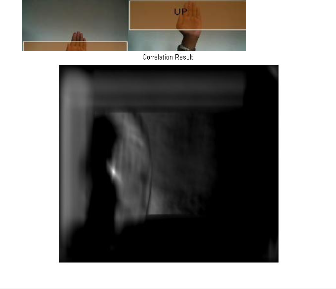
correlation algorithm the motor will rotate and based on the hand movement to recognizes control of the arm and that input word displayed in the monitor and the system is in ready state and ready to be trained and the hand directional movement shows in given below in Figure 8(a) and (b) and also Figure 9 shadow pictures shows that location of the hand position.
Figure 10. Correlation result
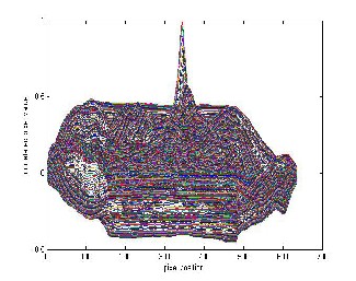
The Image processing technique involves template matching algorithm that uses normal correlation technique to find out the palm on the screen and match it with web cam image. The template image and image from webcam is correlated and the result is a data of -1 to 1 and it is shown in Figure 10 and Figure 11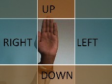
Figure 11. Correlation result plot
Syntax
C = normxcorr2(template, A) (16)
Figure 8(b). Region split up for hand movement
Figure 9. Directional result on hand movement
Normxcorr2 computes the normalized cross- correlation of the matrices template and A. The matrix A must be larger than the matrix template for the normalization to be meaningful. The values of template cannot all be the same. The resulting matrix C contains the correlation coefficients, which can range in value from -1.0 to 1.0.
normxcorr2 uses the following general procedure.
1. Calculate cross-correlation in the spatial or the frequency domain, depending on size of images.
2. Calculate local sums by precomputing running sums.
3. Use local sums to normalize the cross-correlation to get correlation coefficients.
IJSER © 2013 http://www.ijser.org
International Journal of Scientific & Engineering Research, Volume 4, Issue 11, November-2013 1179
ISSN 2229-5518
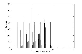
The implementation closely follows above formula. After normal correlation the output of matching is compared with region where it lies and respective movement is established as shown in Figure 12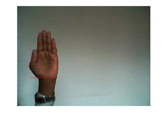
Figure 12. Template matching output
This paper presents the design, development and implementation of robot arm, which has the talent to accomplish simple tasks, such as light material handling. The robot arm was designed and built from acrylic material where servo motors were used to perform links between arms and execute arm movements. The servo motors include encoder so that no controller was implemented; however, the rotation range of the motor is less than 180º span, which greatly decreases the region reached by the arm and the possible positions. The design of the robot arm was limited to four degrees of freedom since this design allows most of the necessary movements and keeps the costs and the complexity of the robot competitively. The end effector is not included in the design because a commercially available gripper is used since it is much easier and economical to use a commercial one than build it.
To control the robot arm, three approaches are implemented: a microcontroller, a driver, and a computer- based user interface. This system has unique characteristics that allow flexibility in programming and controlling method, which was implemented using inverse kinematics; besides it could also be implemented in a full manual mode. This robotic arm is contrast with others as being much cheaper than available robot arms, also it can be controlled all of its
movements from a computer, using a MATLAB interface.
Several tests were carried out to validate the robot arm where the testes covered both the particular elements and the overall system; results at different operating conditions show trustful of the robot arm presented.
[1]Manipulating Industrial Robots—Vocabulary, Interna- tional Organization for Standardization Standard 8373, 1994. [2] Industrial and Service Robots, IFR International Federa- tion of Robotics, 2010. http://www.ifr.org/home
[3] Case Studies and Profitability of Robot Investment, The IFR Statistical Department, 2008. http://www.ifrstat.org/downloads/2008_Pressinfo_english.pdf [4] R. J. Wang, J. W. Zhang, et al., “The Multiple-Function Intelligent Robotic Arms,” FUZZ-IEEE Journal, Korea, 20-24
August 2009, pp. 1995-2000.
[5] L. B. Duc, M. Syaifuddin, et al., “Designing 8 Degrees of Freedom Humanoid Robotic Arm,” International Confer- ence on Intelligent and Advanced Systems, Kuala Lumpur
25-28 November 2007, pp. 1069-1074.
[6] C. R. Carignan, G. G. Gefke and B. J. Roberts, “Intro to Space Mission Design: Space Robotics,” Seminar of Space Robotics, University of Maryland, Baltimore, 26 March 2002. [7] Occupational Safety and Health Administration Technical Manual, OSHA 3167, United States Department of Labor,
1970.
[8] B. Siciliano, L. Sciavicco, L. Villani and G. Oriolo, “Robotics, Modelling, Planning and Control,” Springer, Lon- don, 2009.
[9] M. P. Groover and M. Weiss, “Robotica Industrial, Tech- nologia, Programacion y Aplicaciones,” Mc-Graw Hills, Mexico D.F., 1989.
[10] Iovine J, “PIC Robotics: A Beginner’s Guide to Robotics Projects UsingThe PICmicro”, Mc-Graw Hill, 2004, ISBN.0071394559.
[11] Iovine J, “Robots, Androids, and Animatrons: 12
Incredible ProjectsYou Can Build”, Mc-Graw Hill, 2001, ISBN 0071376836.
[12] Lunt K., “Build Your Own Robot”, A. K. Peters Ltd.,
2000, ISBN1568811020.
IJSER © 2013 http://www.ijser.org