International Journal of Scientific & Engineering Research, Volume 3, Issue 5, May-2012 1
ISSN 2229-5518
Automated Vehicle Input / Output Test Tool
Bhan Sengar, Smita Hulyalkar, Prateek Yadav, Rohit Tikekar, Ashwini Sidhaye
Abstract— This document describes the tool developed to test vehicle input/output (VIO) layer. VIO layer is part of application communication layer in the American Axle software Architecture. This layer extracts the data from Controller Area Network (CAN) Bus and passes the information to control systems.
Index Terms— ECU Electronic Control Unit CAN Controller Area Network
—————————— ——————————
1 INTRODUCTION
ITH increasing number of Electronic Systems in mod- ern automobiles, it is important for the ECUs to commu- nicate through a common platform (usually CAN) and
share information to be a financially viable product.
The VIO layer residing in the ECU act as a bridge between the AAM ECU and other ECUs on the network .Thus, it becomes important to validate the output of VIO layer for efficient use of the information received from other ECUs.
Automated VIO Test tool is developed to reduce the effort, time and improve accuracy against manual testing of VIO.
2 BACKGROUND
The information exchanged between different ECU’s of a ve- hicle is represented using Database file (DBC). The VIO layer is designed so as to receive and transmit data packets (mes- sages) as per information given in the DBC.
The signals received by VIO layer are stored in the variables inside the ECU. The details like address, ranges (max and min values) of the variables are given in the A2L file which is gen- erated during the software compilation time.
The VIO validation process makes sure that any changes in the incoming signal on the DBC file are correctly updated to the corresponding variables inside the ECU memory which in turn determines the system performance.
Till date the validation of VIO layer was done by manually changing the inputs on CAN bus and viewing the changes on the corresponding variables. The automated VIO testing tool automates the process of changing the inputs and recording
————————————————
Autohors are currently working at Electronics Control System, American Axle and Manufacturing Services India Pvt. Limited D#401,402 Weikfield Info Park, Nagar Road Pune 411014
the corresponding updates to the variables. The information recorded is compared to the expected outputs to generate a
test result summary. This speeds up the process of finding and solving the problem.
3 DETAILED DESCRIPTION
There are four steps involved in the development of the tool.
3.1 Mapping of signals
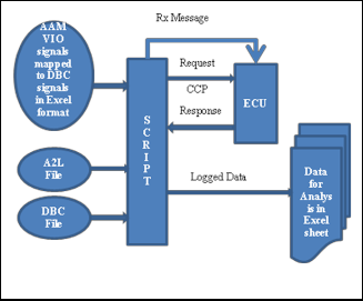
Excel sheet is prepared first in which the signals that are re- quired in the VIO are mapped to the ones in DBC. This sheet contains all the signals with their AAM units, data types, mes- sage Ids in which signals are present in DBC and related in- formation.
Fig.1. Overview
3.2 Extraction of Signal Properties from DBC
A Matlab script (M-script) extracts the details of the all the signals, one by one that are listed in the above prepared excel sheet. The signal information like type, range, resolution, off- set if any is extracted. This information is used for varying the inputs to VIO layer in an automated test environment.
3.3 Extraction of Variable’s Details from A2L
A C program extracts the details like memory location, type, size, and range from A2L file for the variables which are under test. This information then merged with the one extracted from DBC for all the variables and .INI file is created.
IJSER © 2012
http://www.ijser.org
International Journal of Scientific & Engineering Research Volume 3, Issue 5, May-2012 2
ISSN 2229-5518
3.4 Variation of Input Signals to cover the full range
Using the information in INI file, a script sends messages to cover the whole range of the signals.
ECU updates the values of the signals which are received in that particular message. The value of the updated variable is read using the addresses given in the A2L file by CAN Cali- bration Protocol (CCP).
The CCP is basically used as a monitor program which pro- vides basic read and write memory capabilities.
Test cases are made for every signal in which for every value of the signal expected values are written with which the val- ues read by the tool are compared to generate the final report.
4 CONCLUSION
4.1 Reduction in Validation Times
This serves two main purposes: Timely delivery of the product and more importantly quality of the deliverables.
ACKNOLEDGMENT
We would like to acknowledge all the people who helped us complete the paper especially to my supervisor, Mr. Vijay Khatavkar. He offered me good advice, gave me generous support, and guidance. Without his guidance, advice, and en- couragement, I would not have been able to complete the work.
Thanks to the entire ECS team, Mr. Ralph Avolio and Mrs. Malik Priyanka for their invaluable support and guidelines during the entire project duration.
REFERENCES
[1] H. Kleinknecht, “CCP V_2.1Standard Reference document”.
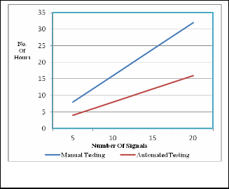
Fig.2. Comparison
As compared to manual testing, automated testing tool takes comparatively less time. The graph shows that amount of time taken to test specified number of test has reduced by almost
50%.
4.2 Reduction in Validation Efforts and Resources
Automated VIO test tool needs minimal interaction from tes- ter. There is no interaction of the user with the tester tool.
4.3 Improved Accuracy
As compared to manual testing which is done on sampling basis, automated test tool test the complete range of the signal as given in the database file. This improves the accuracy of the overall system.
As all the tests are run on every signal, any issues related to any signal are found in the initial level itself rather than on the field test.
IJSER © 2012
http://www.ijser.org