The research paper published by IJSER journal is about Architectural design Of MD5 Controller IP Core 1
ISSN 2229-5518
Architectural design Of MD5 Controller IP Core
Sreeraj C, Sarath K Kumar , Nandakumar.R
Abstract- The MD5, first proposed by R. Rivest is a secure hash algorithm in cryptography that produces a 128-bit message digest from an input message of arbitrary length. It was proposed as one of the authentication options in IPv6.This paper addresses the design of a behavioral model and custom architecture for a controller for the popular MD5, message digest algorithm.
Index Terms – Cryptographic hash function, MD5, Digital signature, Message authentication, Data integrity, VLSI Cryptosystem.
I. INTRODUCTION
Hash functions are mathematical computations that take in a relatively arbitrary amount of data as input and produce an output of fixed size. The output is always the same when given the same input. The inputs to a hash function are typically called messages, and the outputs are often referred to as message digests or simply digests. All hash functions have the property that it is impossible to determine the input knowing only the output. This property makes this hash functions a one-way function, meaning that it is difficult, if not impossible to deduce the input for a given output. There are some hash functions which are much more powerful than ordinary hash functions, they are known as cryptographic hash functions [4]. Cryptographic hash functions have another property that most hash functions do not; the property that it is very difficult to find two different messages that produce the same message digest. Two distinct messages that result in the same digest are called collisions. Since different messages almost always produce different digests, one can conclude that if messages digest of a file changes, then the file itself has changed. This property can be used to provide data integrity and data authentication to a legitimate user. Verification of transmitted and received data ,data origin authentication are essential security services in financial transactions, electronic commerce, electronic mail, software distribution, data storage etc. In internet protocol security (IPSEC) the technique of cryptographic hash functions is utilized to achieve these security services. There are two primarily cryptographic hash functions in use today, MD5 and SHA-1[4]
I.1 MD5 MESSAGE DIGEST ALGORITHM
MD5 stands for “Message Digest 5” because it is the fifth revision of a message digest algorithm devised by R. Rivest of RSA Laboratories. According to RFC 1321[1], “MD5 message-digest algorithm takes as input a message of arbitrary length and produces as output a 128-bit message digest of the input. It is basically a secure version of the previous algorithm, MD4 which is little faster but less secure than MD5. The MD5 algorithm is intended for digital signature applications, where a large file must be "compressed" in a secure manner before being encrypted with a private (secret) key under a public-key cryptosystem such as RSA [2].
II. PRINCIPLE OF OPERATION.
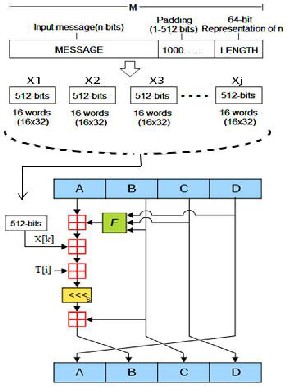
For an n-bit input message (where n is an arbitrary non negative integer) the MD5 encryption process involves the following steps [1] and is depicted in figure 1.
1. PADDING
Bit padding method is used here, that is a single set ('1') bit is added to the input message and then as many reset ('0') bits as required are added. The number of reset ('0') bits added will depend on the block boundary to which the message needs to be extended. Here the block boundary is
448 modulo 512.That is, the message is extended so that it is
64 bits less than being a multiple of 512 bit long. Padding is
always performed even if the length of the message is
already congruent to 448 modulo 512.In all case at most 512 bits and at least 1 bit are appended.
IJSER © 2012 http://www.ijser.org
The research paper published by IJSER journal is about Architectural design Of MD5 Controller IP Core 2
ISSN 2229-5518
2. APPENDING THE LENGTH.
To the result of previous step, a 64 bit representation of input message is concatenated, so that it becomes a multiple of 512 bits and equivalently this message has a length that is an exact multiple of 16 words (32 bits).In the rare case that input message length n> 264 , then only the lower order 64 bits of message are used. Here the appended message is represented as M, shown in figure 1.
3. MD BUFFER INITIALIZATION.
Let (A, B, C, D) is a four-word MD buffer. Each of A, B, C, D is a 32-bit register and they are initialized with the following hexadecimal values.
WORD A: 67 45 23 01
WORD B: ef cd ab 89
WORD C: 98 ba dc fe
WORD D: 10 32 54 76
Note that the lower order bytes of the initial values, given in [1] are entered first.
4. PROCESSING OF THE 512(16-WORD) - MESSAGE BLOCKS
The appended message M contains blocks of 512 bits which are processed separately by an algorithm. Let Xj denote the jth block of M. The algorithm consist of four rounds of 16 steps each, that is, a total of 64 steps are performed. The following operation is performed for each step.
A=B+ ((A+ function(B,C,D)+ Xj [k]+T[i]<<<s) Where,
i = Index of step.
Xj[k] = Kth , 32-bit word of Xj.
T[i] = Table of 64, 32-bit constants.
s = Number of bits to be shifted in circular shift operation
(<<<)
round (16 ≤ i ≤ 31) function G(X, Y, Z) is used. For third
round (32 ≤ i ≤ 47) function H(X, Y, Z) is used. For fourth round (48 ≤ i ≤ 63) function I(X,Y,Z) is used. Operations done by each auxiliary function is given below.
F(X, Y, Z) = (X AND Y) OR (NOT(X) AND Z) G(X, Y, Z) = (X AND Z) OR (Y AND NOT (Z)) H(X, Y, Z) = X XOR Y XOR Z
I(X, Y, Z) = (Y XOR (X OR NOT (Z))
After each round the values stored in registers got shuffled. The value in D is stored in A, value of A is stored in B, value of B is stored in C and value of C is stored in D. At last the values obtained from the algorithm are added with the values stored in temporary variables.
5. OUTPUT
After processing of all 512-bit blocks with the algorithm, the message digest of n-bit message is in A, B, C and D. The lower order byte of A represents the first byte of MD5 output. The higher order byte of D represents the last byte of MD5 output.
The value of k, s and T[i] are taken from table 1 in accordance with the index value i. T[i] denotes the ith element of table, which is equivalent to the integer part of
4294967296 times abs(sin(i)).
Function (B, C, D) is different for each round. For first
round (0 ≤ i ≤ 15) function F(X, Y, Z) is used. For second
FIGURE 1: MD5 PROCESSING STEPS.
IJSER © 2012 http://www.ijser.org
The research paper published by IJSER journal is about Architectural design Of MD5 Controller IP Core 3
ISSN 2229-5518
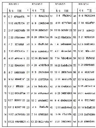
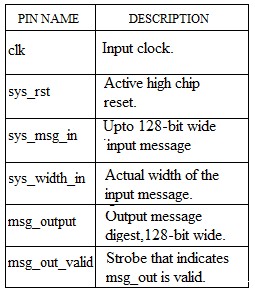
TABLE 2: PIN DESCRIPTION
The behavioral model of the custom controller for MD5
Core [5] may be abstracted as a finite state machine, as
depicted in figure 3
TABLE 1: Values of k, s and T[i]
III. I/O DIAGRAM OF CONTROLLER- CORE WRAPPER
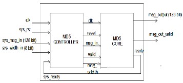
FIGURE 2: WRAPPER FOR MD5 CORE CONTROLLER The I/O Diagram of MD5 core with controller is shown in
figure 2. It has five input strobes and three output strobes.
Functions of each strobe are depicted in Table 2.
FINITE STATE MACHINE:
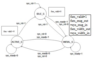
FIGURE 3: FSM FOR CUSTOM CONTROLLER.
IJSER © 2012 http://www.ijser.org
The research paper published by IJSER journal is about Architectural design Of MD5 Controller IP Core 4
ISSN 2229-5518
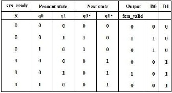
From the behavioral model shown in figure 3, suitable excitation signals are tabulated as given in table 3, below.
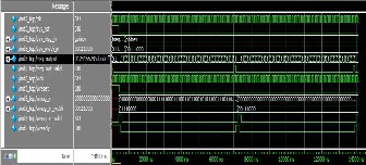
FIGURE 5: FUNCTIONAL SIMULATION RESULT
TABLE 3: EXITATION TABLE
The Karnaugh map simplified equations for fsm_valid, D0 and D1 from the above shown excitation table are given below and the circuit synthesized from is depicted in figure
4.

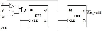
FIGURE 4: STRUCTURAL MODEL FOR MD5
CONTROLLER
Where R represents the Ready input of controller,q1,q0 represents present state, fsm_valid represents the controller output.
V. SIMULATION RESULT
Functional simulation of the IP core was done using Mentor Graphics Modelsim® SE, using custom test benches.The timing digram obtained and note about sample test case are given below.
Note on Simulation result: At first clk pulse
Sys_rst =”1” Sys_msg_in=”message digest” Sys_msg _width=”8’h70”
Msg_out=”0123456789abcdeffedcba9876543210” Msg_out_valid=”x”
At second clk pulse
Sys_rst =”0”
Sys_msg _in=”message digest” Sys_msg _in_width=”8’h70” Msg_out=”0123456789abcdeffedcba9876543210” Msg_out_valid=”0”
At 64th clk pulse Sys_rst =”0” Sys_msg_in=”message digest” Sys_msg_in_width=”8’h70”
Msg_out=”f96b697d7cb7938d525a2f31aaf161d0”
(message digest) Msg_out_valid=”1”
After 64 clk pulses (next input value enters) Sys_rst=”0”
Sys_msg _in=”verilog” Sys_msg _width=”8’h38” Msg_out=”0123456789abcdeffedcba9876543210” Msg_out_valid=”0”
And the process continues.
IJSER © 2012 http://www.ijser.org
The research paper published by IJSER journal is about Architectural design Of MD5 Controller IP Core 5
ISSN 2229-5518
VI. SYNTHESIS RESULTS
The soft IP Core [5] along with a custom controller was synthesized to obtain structural equivalent, using Altera® Quartus II, targeting FPGA EP2C2OF484C7, a platform FPGA belonging to cyclone II® family.
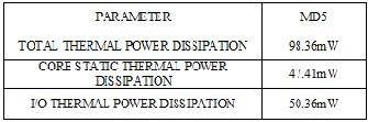
TABLE4: POWER ANALYSIS REPORT
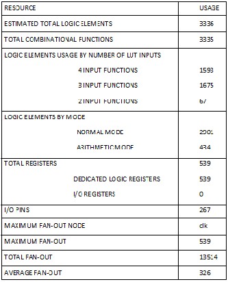
TABLE5: RESOURCE UTILIZATION REPORT VII. CONCLUSION
The systematic design of a custom controller core for the
popular message digest algorithm, MD5 has been described. The controller is designed with easy to use fully stall-able interfaces both for core input and output. These are intended to allow the user’s application to cease the data stream from the core when it is not able to receive data or to stop the input stream towards the core according to
data arrival rate. Also the controller core has been
characterized for different hardware efficiency parameters, to serve as a bench mark for adoption in wide variety of user applications.
VIII.REFERENCES
[1] R. Rivest, The MD5 Message-Digest Algorithm, RFC
1321, MlT LCS & RSA Data Security, Inc.,April 1992. [2] RSA Laboratories, PKCS#1 v2.1: RSA Cryptography
Standard,June 14, 2002
[3] Kimmo Järvinen, Matti Tommiska and Jorma Skyttä,
“Hardware Implementation Analysis of the MD5
Hash Algorithm,” in Proceedings of the 38th Annual Hawaii International Conference on System Sciences vol. 09, pp. 298.1, 2005
[4] B. Schne K. Järvinen, M. Tommiska, and J. Skyttä.
Compact Combined MD5 and SHA-1 Hash Module. Submitted to the 25th IEEE International Conference
on
Distributed Computing Systems, ICDCS 2005, Columbus, Ohio, USA, June 6 – 9, 2005
[5] Sreeraj.C, Sharath K Kumar, Nandakumar.R, “Design and Characterization of MD5 IP Core”, International Journal on Computer Science and Technology (IJCST), Vol. 3. Issue 4. October – December, 2012
IJSER © 2012 http://www.ijser.org